

RF Hunter HF FOG130 Installation Manual

INFORMATION ENCLOSED:
HF 080, HF 130 & HF 165
•
Specifications
•
Assembly & Operating Instructions
•
Parts List
•
Service Instructions
ECCO ONE
•
Specifications
•
Assembly & Operating Instructions
•
Parts List
•
Service Instructions
MINI MAX III
•
Specifications
•
Assembly & Operating Instructions
•
Parts List
FOG 065 & FOG 130
•
Specifications
•
Assembly & Operating Instructions
•
Parts List
•
Service Instructions
Important Information
Filter Powder Instructions
Limited Warranty
Important Safety Instructions
Fryer Puck Information
2011 List Pricing
2011 Filtrator Price List
2011 ECCO ONE Price List
2011 MINI MAX Price List
2011 FOG Price List
2011 Standard Stock Items with Pricing
ITEM # _______________
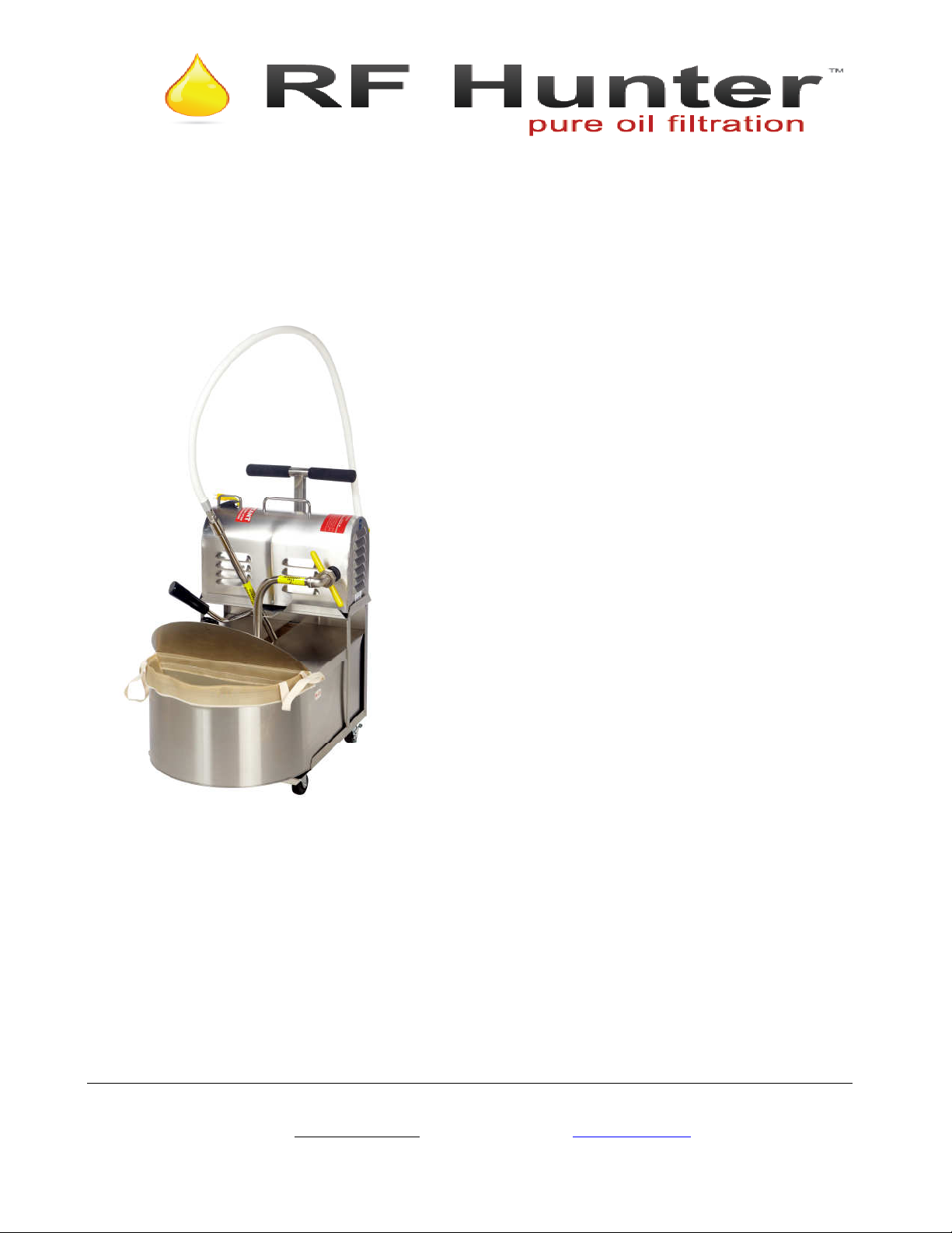
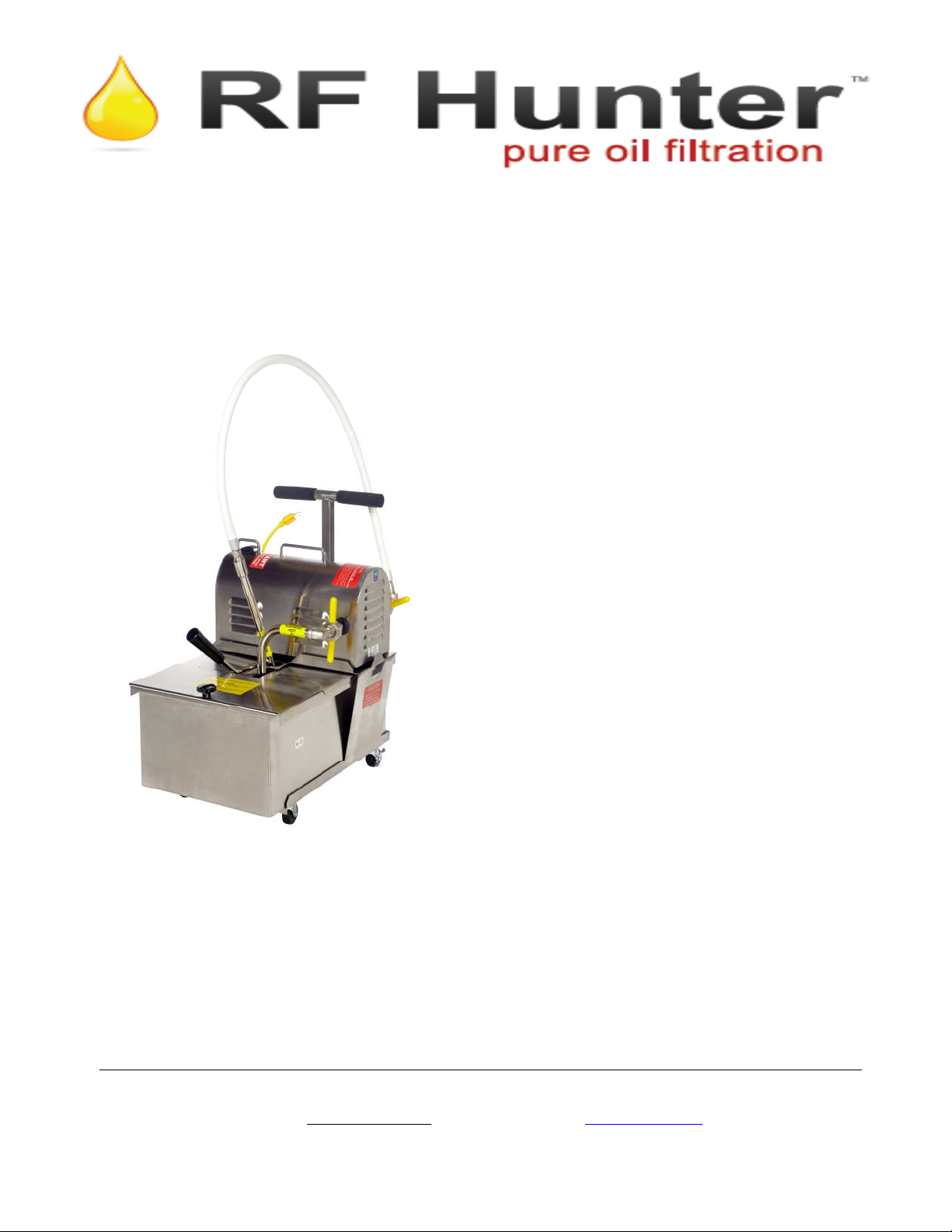
R.F. HUNTER CO., INC. FILTRATOR (Electric)
FILTRATOR (Electric)
R.F. Hunter Co., Inc. has been designing, selling and servicing
commercial quality filtrators for over 65 years. We offer a full
range of models and sizes to accommodate
65 lb. to 130 lbs. and F.O.G. units at 65 lbs. and 130 lbs. plus
filters, Filtrator compound and replacement parts.
MODEL # HF 80, HF 130 & HF 165
Description
All FILTRATOR filters are completely
self contained - cart, container and power
unit combined into one compact portable
unit. The container, container cover, cart,
power unit housing, base, and “T” handle
are stainless steel. All other exterior
surfaces are nickel-plated steel. Pumps
are specially machined to handle high
temperature edible oils. The specially
fabricated 48” hose is designed for the
same purpose with embedded wire
reinforcement. The unit is equipped with
a ½ H.P. heavy-duty motor. The 15 ½ x
15 ½ square screen can be used with either
a cloth filter for heavy sediment
conditions or a paper envelope for light
sediment conditions.
Electrical Specifications
110-115 VAC, ½ H.P., 60 HZ, 8.8-7.4
AMP, 1.0 SF. Equipped with oil proof
lead wire cord and molded 3 prong
grounding plug. Thermal and torque
overload protection also provided.
Standard Accessories
2 Filter Cloths Bags (FB03) or
50 Filter Paper Envelopes (FE09)
25 Ind. Packets of Filter Powder (FP22D)
Pre Filter Assembly for HF 80 (FA09)
Pre Filter Assembly for HF 130/165
(FA10)
Optional Accessories
Extension Cord
113 Crosby Road, Suite. #9, Dover, NH 03820-4370
Tel: (603) 742-9565 Fax: (603) 742-9608 (800) 332-9565
Email: sales@rfhunter.com Visit our website at: www.rfhunter.com
HF SERIES ELEC FRONT 1-11
ITEM # _______________
SPECIALISTS IN KITCHEN ECONOMY SINCE 1945
MODEL #: HF SERIES
R.F. HUNTER CO., INC.
HF 80 (ELECTRIC)
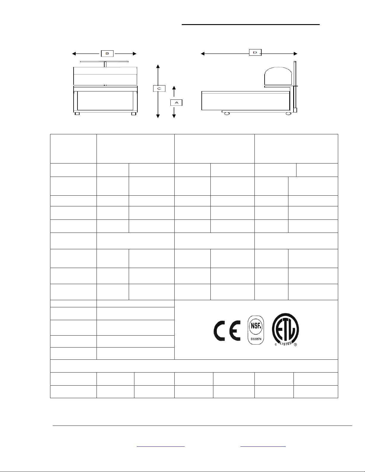
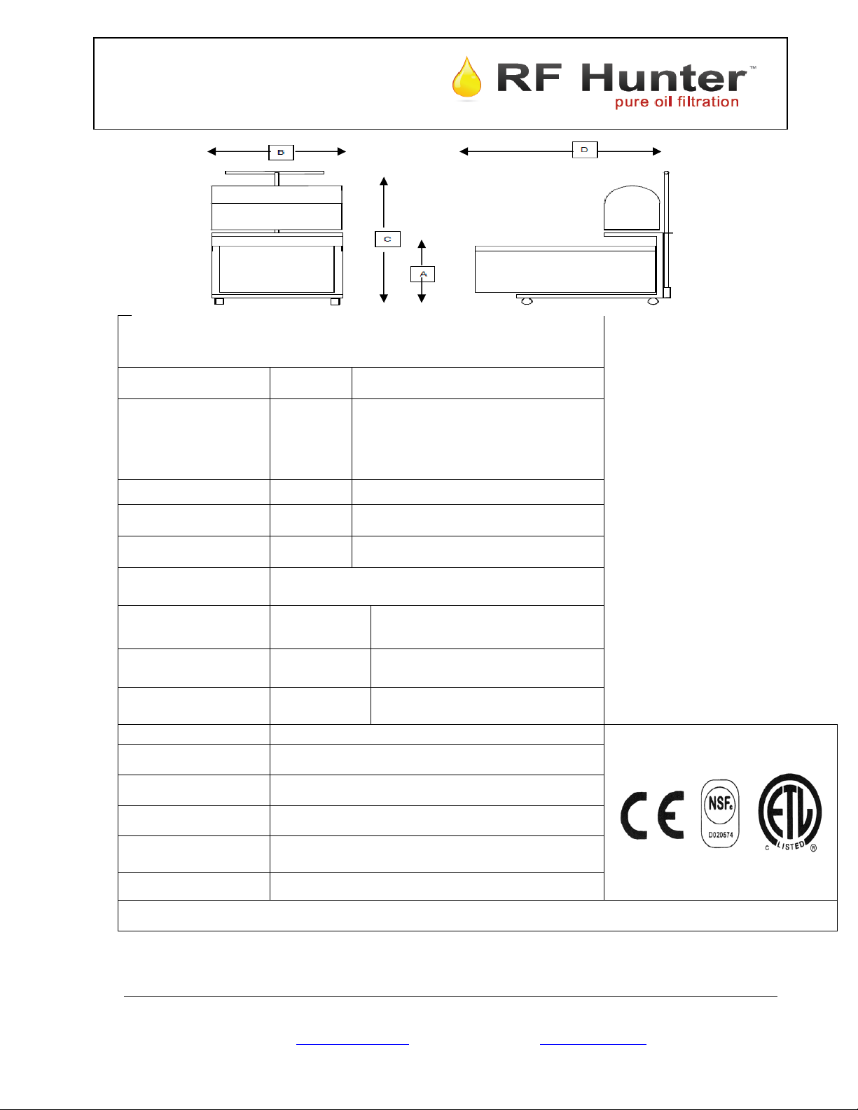
DIMENSION
A
B 16.375” 41,59 cm 19.375” 49,21 cm 19.375” 49,21 cm
C 27” 68,58` cm 27” 68,58 cm 31.75” 80,61 cm
D 26.50” 66,25 cm 30.5” 77,47 cm 30.50” 77,47 cm
Filter Media Cloth Bag or Paper Envelope Cloth Bag or Paper Envelope Cloth Bag or Paper Envelope
Container
Capacity
Shipping
Weight
Shipping Cube*
Electrical (ALL MODELS)
Volts 110-115
112 lbs 50,89 Kgs 122 lbs 55,42 Kgs 127 lbs 57,68 Kgs
12.5 cu.
MODEL
HF 130 (ELECTRIC)
US METRIC US METRIC
11.75” 29.85 cm 11.75” 29,85 cm 15.25” 38,74 cm
80 lbs. 36,3 litres 130 lbs 58,9 litres 165 lbs. 74,8 litres
Ft.
,35 cu. Meters 12.5 cu. Ft. , 35 cu. Meters 12.5 cu. ft. ,35 cu. meters
MODEL
MODEL
HF 165 (ELECTRIC)
US METRIC
Amps 8.8-7.4
Phase 1
HZ 60
* If shipped common carrier. Shipment via UPS in two boxes :
Power Unit 2.6 cu. Ft. ,07 cu. meters 2.6 cu. Ft. .07 cu. meters 2.6 cu. Ft. ,07 cu. meters
Container Body 5.1 cu. Ft. ,18 cu. meters 8.3 cu. Ft ,14 cu. Meters 8.3 cu. Ft. ,14 cu meters
R.F. HUNTER CO., INC. FILTRATOR - ELECTRIC
113 Crosby Road, Ste. #9, Dover NH 03820-4370
Tel: (603) 742-9565 Fax: (603) 742-9608 (800) 332-9565
Email: sales@rfhunter.com Visit our website at: www.rfhunter.com
HF SPEC BACK E 1-11

HF
ELEC AOI
1-11
H F S E R I E S
A s s e m b l y & O p e r at i n g I n s t r u c t i o n s
Before attaching hoses to the power unit, make sure the motor is operative by plugging it into an electrical outlet and
turning on the switch. If the motor does not run, turn it off immediately and refer to the “SERVICE INSTRUCTIONS”
sheet for information. Please read the important safety instruction sheet before operating.
ASSEMBLY INSTRUCTIONS
Slide container into cart with square end to the rear of cart. Place power unit on
top of the cart with the ‘SUCTION” side (see arrow on label on top of power unit)
facing toward the container.
Filter Screen Assembly – Place filter cloth bag or paper envelope over the screen
so that the hole of the cloth bag or the paper envelope allows the threaded stem of
the filter screen to poke through. Fold cloth bag or paper envelope over the top of
the screen and place clamp over the screen to hold filter in place. Attach filter
screen stem to screen and place the filter screen assembly in the container. The
clamped end of the filter screen should be toward the rear end of the container.
Attach union nut to “SUCTION” side of the power unit. Tighten union nut by
hand only.
Once the filter screen assembly is in place, slide the container cover over the
container. The four slots of the cover should face toward the front end of the
container. The half round piece of the cover is assembled by placing the tabs
through the slotted holes.
Attach discharge hose and nozzle to “DISCHARGE” side of the power unit and
hand tighten the union nut. (Never use wrench to tighten).
Slide the “T” handle into the handle holder on the cart. Insert retaining pin
through both sides of the “T” handle holder bracket.
ASSEMBLY OF YOUR PRE FILTER
CAREFULLY place the long rod support through the top opening of the PRE
FILTER material.
Place the support rod on the container rim with the round portion of the filter
facing the rounded end of the container.
Place the flap of the PRE filter over the edge of the container. This will secure the
filter in place.
Your HF Series is now assembled & ready to operate using the operating
instructions below
OPERATION WITH YOUR PRE FILTER
Drain the oil from the fryer through the Pre filter into the container. The sediment will
become trapped allowing the oil to pass through. Once the filtering is completed and
the oil is returned to the fryer, remove the filter to your cleaning area. CAREFULLY
lift the Pre filter from the container. Allow any residual oil to drain from the Pre filter.
Once the oil has drained, dump the sediment into your waste receptacle. Wash, rinse
and dry the Peek filter and return it to its position on the container.
OPERATING INSTRUCTIONS
CAUTION: Oil/shortening will cause parts to become hot. Use care when handling to
avoid injury.
Open the door of the fryer and roll the HF SERIES up to the fryer so that the front end
of the container is under the drain valve. Plug power unit into an electrical outlet.
You are now ready to begin draining your frypot and filtering your oil/shortening.
With oil/shortening at approximately 300°F, turn off fryer and take out the
crumb screen. Sprinkle one cup (8 oz. By volume) of FILTER POWDER
into the oil/shortening per 35-40 lbs. of oil. Mix the powder into the
oil/shortening. Lift the round half piece on the cover to an upright position
to allow oil to drain into the container. When properly positioned, the
rounded cover acts as a splashguard. Open the fryer drain valve to allow
oil/shortening to drain into the HF SERIES container. Turn on the power
unit. Caution: Make sure nozzle points toward the bottom of the fryer.
Oil/shortening will be recirculated into the fryer, and by directing the
nozzle, sediment can be washed out of the frypot. When the sediment has
been completely washed out from the fryer, turn power unit off. Close
fryer drain valve, and turn on power unit. The filtered oil/shortening is
now being pumped back into the fryer.
When the oil/shortening is returned completely to the fryer, turn off the power
unit, unplug and remove the HF SERIES. Replace crumb screen and turn
on the fryer. The fryer is now ready to use.
CARE & CLEANING OF HF SERIES
CAUTION: Be sure parts have cooled before handling/cleaning.
Remove the HF SERIES to your cleaning area. Remove cover from the
container and disconnect the filter screen assembly. Turn power unit 90° so that
the discharge and suction side of the power unit overhang the shelf of the cart.
Disconnect the discharge hose/nozzle from the power unit. Allow oil/shortening
to drain from the discharge hose into the container. Put hose aside. Tip power
unit so that the discharge side of the power unit faces down toward the container
to allow the oil/shortening to drain from the pump. Return power unit to its
proper position on the shelf of the cart.
DRAINING THE PUMP IS EXTREMELY IMPORTANT
If the pump is not drained, hardened oil/shortening may prevent the pump from
rotating when the power is supplied to the motor.
While holding the screen assembly over the container, shake the screen to
remove sediment from the cloth bag or paper envelope. Remove stem from
screen and then remove cloth bag or paper envelope from the screen. Clean the
screen stem assembly, container, cover, discharge hose/nozzle by washing,
rinsing and thoroughly drying each part. The screen can be separated by holding
the screen upside down and gently tapping the threaded stem on a hard surface.
The cloth filter bag can be reused once it has been washed. The power unit
housing, cart and outside parts of the container can also be cleaned using a
stainless steel cleaner/polish.
NOTE: DO NOT RUN WATER THROUGH PUMP.
After the HF SERIES has been cleaned, reassemble the various components,
replace the cloth filter bag or paper envelope on the screen. Attach the screen
stem to the power unit as well as the nozzle/DHA. Replace the pre filter on the
container and the unit is ready for the next filter cycle.
113 Crosby Road, Ste. #9, Dover, NH 03820-4370
Tel: (603) 742-9565 Fax: (603) 742-9608 (800) 332-9565
Email: sales@rfhunter.com Visit our website at: www.rfhunter.com
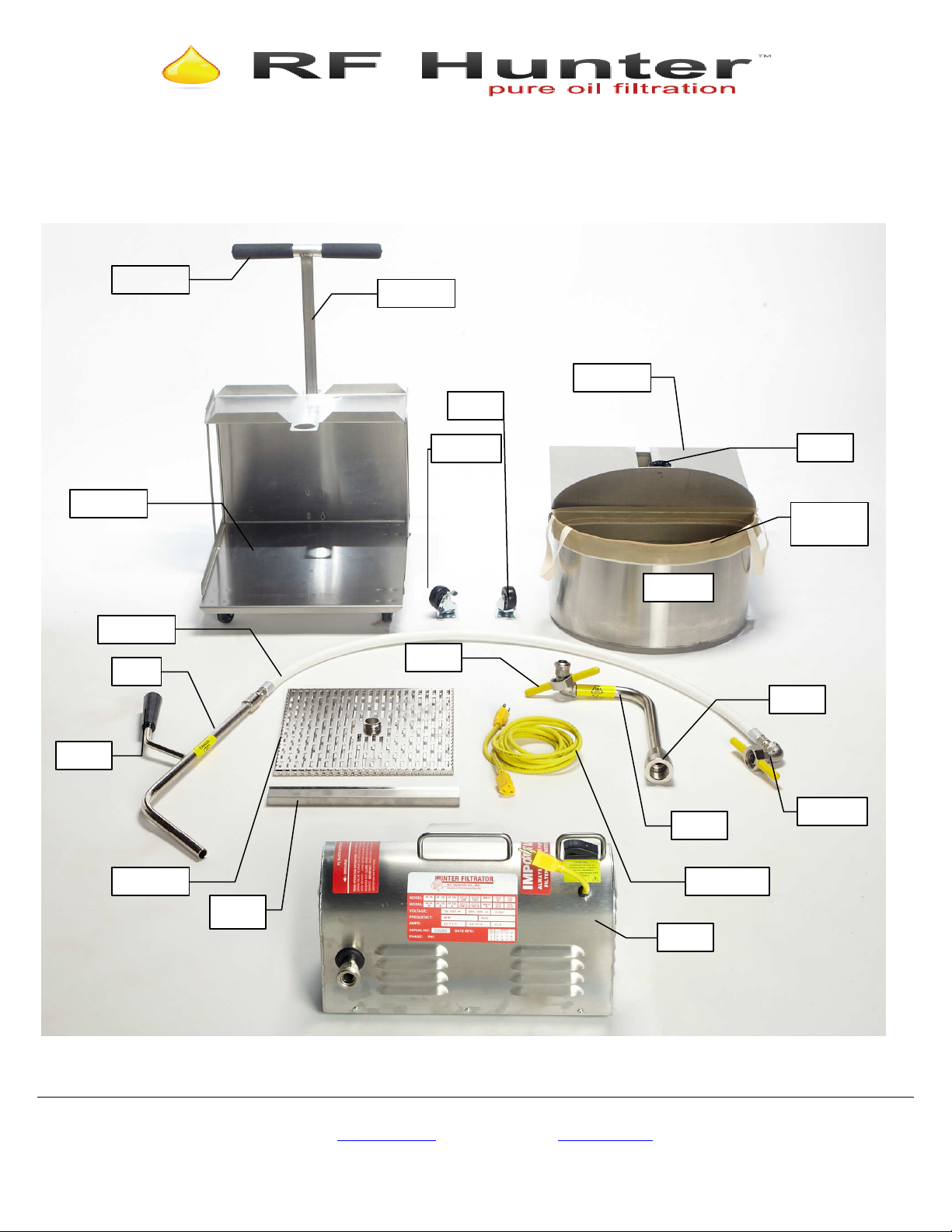
HF05048
HF03PB
HF11
HF04A
HF28
HF27
HF26
HF091
HF SERIES
P
arts List
(Electric)
HF2515
HF18EXT
HF09
*HF02
HF92
*HF04
FA09
HF91CL
HF03P
FA10
HF12
*HF01
HF18EXT
HF13
See enlarged view of FILTRATOR™ Power Unit (HF13) on reverse side.
113 Crosby Road, Ste. #9, Dover NH 03820-4370
Tel: (603) 742-9565 Fax: (603) 742-9608 (800) 332-9565
Email: judy@rfhunter.com Visit our website at: www.rfhunter.com
HFPLFRONT 9-10
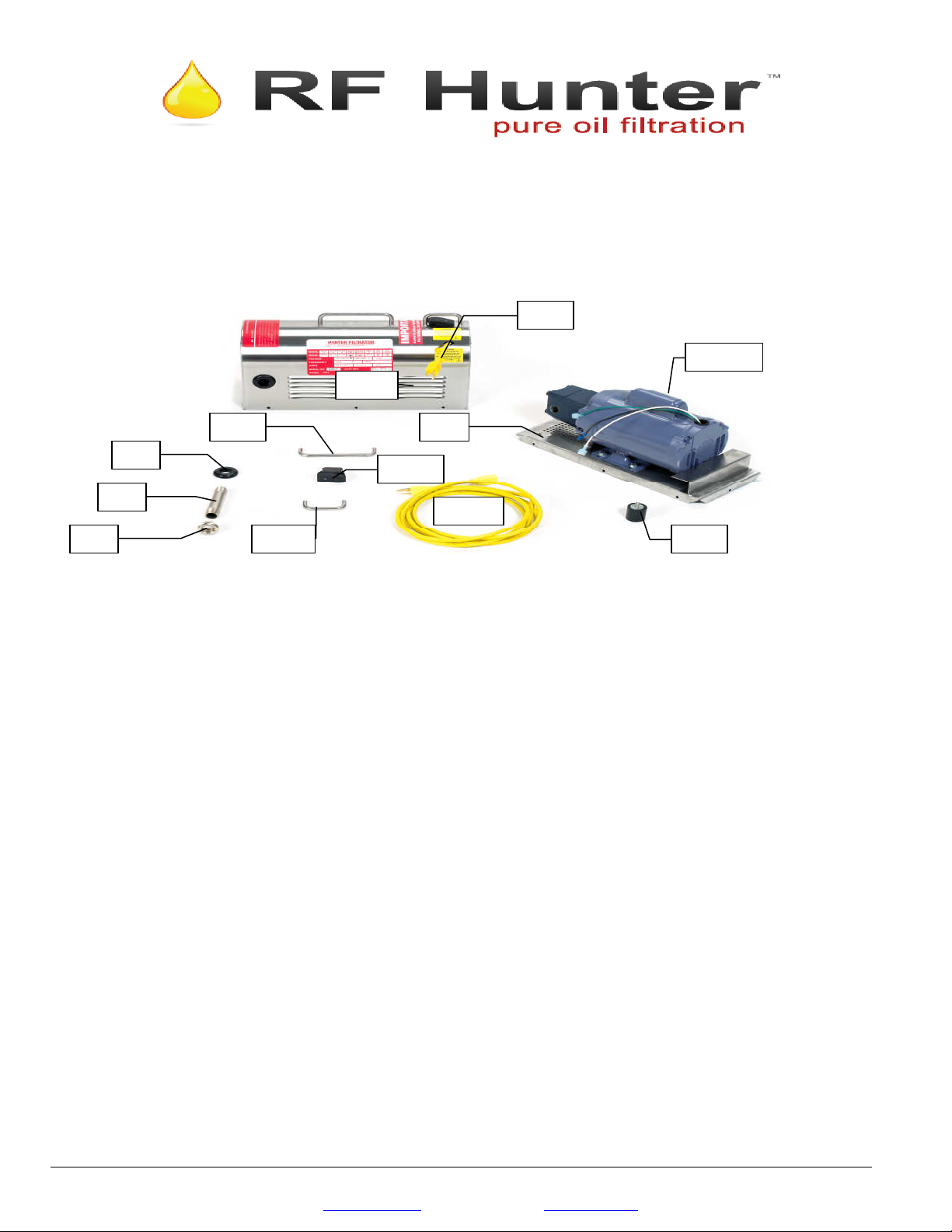
* HF01 CONTAINER
HF091 UNION NUT ASSEMBLY
HF21 MOTOR/PUMP
HF21C CLOSED COUPLING PUMP & MOTOR
HF20
HF16WP
HF18D
HF21C
HF22
HF23 HF16G
HF14
HF19
HF17
HF155
HF SERIES PARTS LIST
HF18EXT
Stainless steel construction rectangular with one rounded end.
All containers have corners.
For Models:
80 (24”L x 16”W x 8.5”D)
130 (28”L x 19”W x 8.5”D)
165 (28”L x 19”W x 12”D)
* HF02 CART
Stainless steel frame with four 2” diameter casters mounted
underneath. For Models:
80 (18 ¼ ”L x 16 ¼”W x 11 ½””D)
130 (19 ¾” L x 19 ¼”W x 11 ½”D)
165 (19 ¾”L x 19 ¼”W x 15 ¼”D)
HF03P CASTER
2” diameter wheel located under cart.
HF03PB CASTER WITH LOCK
2” diameter. Wheel with lock located under cart.
* HF04 CONTAINER COVER
Two piece stainless steel, round with knob and rectangular
with slot. For Models:
80 ( 16 ¼” x 24 ¼”)
130 (19 ¼” x 28”)
165 (19 ¼” x 32”)
HF04A CONTAINER COVER KNOB
Black, round attaches to ½ round piece of container cover.
HF05048 DISCHARGE HOSE
½” diameter., 48” length, wire reinforced hose with 2 hose
nipples and ferrules.
HF06048 DISCHARGE HOSE ASSEMBLY
½” wire reinforced hose with 2 hose ferrules and 2 hose
nipples and union nut assembly. 48” long.
HF07 STREET ELBOW
½” 90° street elbow attached to hose nipple and/or screen
stem piping. Part of union nut assembly.
HF08 BALL END
Screws onto ½” street elbow and attaches union nut to the
pump nipple socket. Part of Union Nut Assembly (HF091)
HF09 UNION NUT
Octagonal shaped with 2 molded yellow handles, inside
thread. Attaches screen stem assembly and discharge hose
assembly to pump nipple sockets of power unit. Part of
HF091-Union Nut Assembly.
Consists of HF07, HF08 & HF09. Attaches discharge hose
and stem assemblies to pump nipple sockets.
HF1106 48” DHA WITH NOZZLE
Consists of HF06048 & HF11.
HF11 DISCHARGE NOZZLE
Nickel plated pipe with black handle. Attaches to
discharge hose assembly.
HF12 DISCHARGE NOZZLE HANDLE
Black, phenolic, to fit discharge nozzle.
HF13 POWER UNIT
Stainless Steel Construction “Mailbox” shape, includes
motor/pump combination, housing., base, housing handle,
rocker switch, rocker switch guard, lead wire, pump
nipples/sockets, grommets & base.
HF14 POWER UNIT HOUSING
Stainless steel “Mailbox” cover. Includes housing handle,
grommets, switch, switch guard & lead wire.
HF155 POWER UNIT HOUSING HANDLE
Located on top of Power Unit Housing
(5” center to center).
HF16WP2 POWER UNIT SWITCH (Rocker)
Black phenolic rocker on/off switch.
HF16G POWER UNIT SWITCH GUARD
HF17 GROMMET
Black rubber piece located on each side of power unit
housing.
HF18D LEAD WIRE ( 6 inches in length)
3 wire electrical cord.
HF18EXT EXTENSION CORD
Lead wire extension cord.
HF19 PUMP NIPPLE
½” x 4” nickel plated piping, screws into pump through
power unit housing.
HF20 PUMP NIPPLE SOCKET
Attaches to pump nipple. Union nut screws onto socket to
attach discharge hose or stem assembly to power unit.
HF20C PUMP NIPPLE SOCKET ASSEMBLY
Consists of HF19 & HF20.
113 Crosby Road, Ste. #9, Dover NH 03820-4370
Tel: (603) 742-9565 Fax: (603) 742-9608 (800) 332-9565
Email: judy@rfhunter.com Visit our website at: www.rfhunter.com
One piece, closed coupling motor/pump combination. For pre
2001 Power Unit Models.
WITH CAPACITOR
One piece, closed coupling motor/pump combination. For
power units sold after 2001.
HF22 POWER UNIT BASE
Stainless steel rectangular piece with base feet and plastic
cover for reset button access.
HF23 BASE FEET
Located on bottom of the power unit base.
* HF24 SCREEN STEM ASSEMBLY
Includes rectangular 2 piece screen (HF2515), screen stem
nut (HF26), stem piping (HF27), union nut assembly
(HF091) & clamp (HF28).
80 & 130 (1/2” x 13 ¼”)
165 (1/2” x 171/2 ”)
HF2515 FILTER SCREEN
2 piece nickel plated filter screen 15 ½” x 15 ½”. Used
with filter paper envelope (FE09) or square cloth filter bag
(FB03).
HF26 SCREEN STEM NUT
Cone shaped nut attached to piping. Screws onto threads
of square screen.
* HF27 SCREEN STEM PIPING
One piece ½” diameter nickel plated piping, bent in one
location. For Models:
80 & 130 (1/2” x 13 ¼”)
165 (1/2” x 17”)
HF28 CLAMP
Stainless steel construction used to hold paper envelope on
filter screen.
HF91CL “T” HANDLE ASSEMBLY
HF92 HANDLE GRIP FOR “T”
HANDLES
HF93 RETAINING PIN
For “t” handle not shown.
FA09 PRE FILTER ASSEMBLY FOR HF80
FA10 PRE FILTER ASSEMBLY FOR HF130/165
HFPLBACK 1-11

SERVICE INSTRUCTIONS
ELECTRIC
These s e r v i c e i ns t r u c tions a r e i n t e n d e d a s a gui de t o c o r r e c t ce r t ai n
proble m s t h a t m a y be enc o un t e re d. If y o u h a v e any que s ti o n s , pl e a se c al l
the S e r v i c e De pa rt m e nt a t 1- 80 0 -3 3 2 - 9 56 5 .
CAUTION: ALWAYS UNPLUG UNIT BEFORE WORKING ON ELECTRICAL ITEMS.
PROBLEM PROBABLE CAUSE CORRECTIVE ACTION
1. Motor does not work
A) Loose or Broken Wire 1. Loose Wire – reattach wire to proper
B) Reset Button not Positioned Correctly 2. Remove clear plastic plug from the
terminal on switch or motor.
Broken Wire – replace with a new
one rated the same as the original.
bottom of the power unit base, reach
in and push in red button on the
motor until a “click” is heard.
Replace plastic plug before
resuming operation. For older
models it is necessary to remove the
housing to reach the reset button.
C) Defective Switch 3. Replace Switch
D) Defective Motor
E) Hardened oil/shortening in pump 5. Remove pump, disassemble and,
NOTE: To replace any component inside the Power Unit other than the fuse requires the removal of the Power Unit Housing Cover.
4. Replace Motor
using a clean cloth, remove
hardened oil/shortening from gears
and inside of pump. Reassemble
pump and insure gear shaft rotates
freely before attaching pump to
motor. Reset red button on motor.
PROBLEM PROBABLE CAUSE CORRECTIVE ACTION
1. Lack of Suction or Discharge
Action
A) Hardened oil/shortening in pump
B) Hardened oil/shortening in hose
C) Loose Fittings 8. Check tightness of fittings at screen,
C) Overused Filter Cloth Bag or Filter
Paper Envelope
D) Cracked and/or Swollen Hose
6. See 5 above.
7. Place hose near heat source to
loosen hardened oil/shortening.
Place drip pan under hose to contain
oil.
stem, ball end, union nut and pump
nipple socket.
9. Replace Cloth Filter Bag or Filter
Paper Envelope.
10. Replace Hose
113 Crosby Road, Ste. #9, Dover, NH 03820-4370
Tel: (603) 742-9565 Fax: (603) 742-9608 (800) 332-9565
E-mail:
sales@rfhunter.com
Visit our website at
www.rfhunter.com
HFSI ELEC 9-10
ITEM # _______________
R.F. HUNTER CO., INC. ECCO ONE (Electric)
ECCO ONE (Electric)
R.F. Hunter Co., Inc. has been designing, selling and
servicing commercial quality filtrators for over 65 years.
We offer a full range of models and sizes to accommodate
65 lb. to 165 lbs. and FOG units at 65 lbs. and 130 lbs. plus
filters, filter powder and replacement parts.
MODEL # ECCO ONE
Description
The ECCO ONE is a 65 lb. capacity filter
designed to be used with drain type fryers.
The compact design allows for ease of
operation and storage. All metal parts are
either stainless or nickel plated steel
which provides years of carefree use. The
hose, motor and pump are specially
constructed to handle the high
temperature edible oils. The two piece
container cover provides protection to the
operator during operation. The front part
lifts to form a splashguard and the rear
portion prevents objects from falling into
the container.
Electrical Specifications
110-115 VAC, ½ H.P., 60 HZ, 8.8-7.4
AMP, 1.0 SF. Equipped with heavy duty
switch, oil proof lead wire cord and
molded 3 prong grounding plug. Thermal
and torque overload protection also
provided. Heavy-duty ½ H.P. Motor.
Standard Accessories
50 Filter Paper Envelopes (FE02)
25 Ind. Packets of Filter Powder (FP22D)
Pre Filter Assembly (FA11)
Optional Accessories
Extension Cord (HF18EXT)
113 Crosby Road, Suite. #9, Dover, NH 03820-4370
Tel: (603) 742-9565 Fax: (603) 742-9608 (800) 332-9565
Email: sales@rfhunter.com Visit our website at: www.rfhunter.com
ECCO SPEC FRONT E USA 1-11
ITEM
#______________
MODEL#: ECCO ONE ELECTRIC
SPECIFICATIONS
DIMENSION
A
US METRIC
12.00” 30,48 cm
B 17.75” 45,09 cm
C 27” 68,58 cm
D 22.00” 55,88 cm
Filter Media Cloth Bag or Paper Envelope
Container Capacity 65 lbs. 29,5 litres
Shipping Weight 107 lbs 48,62 Kgs
Shipping Cube* 12.5 cu. Ft. ,35 cu. Meters
Electrical
Volts 110-115
Amps 8.8-7.4
Phase Single
HZ 60
Plug Configuration NEMA 5-15P
R.F. HUNTER CO., INC. ECCO ONE ELECTRIC
* If shipped common carrier. Shipment via UPS in two boxes of 2.6 cu. Ft. (,07 cu meters) and 6.2 cu. Ft. (,18 cu meters)
113 Crosby Road, Ste. #9, Dover NH 03820-4370
Tel: (603) 742-9565 Fax: (603) 742-9608 (800) 332-9565
Email: sales@rfhunter.com Visit our website at: www.rfhunter.com
ECCO SPEC BACK E USA 1-11
 Loading...