

Page 1
www.rfdesign.com.au
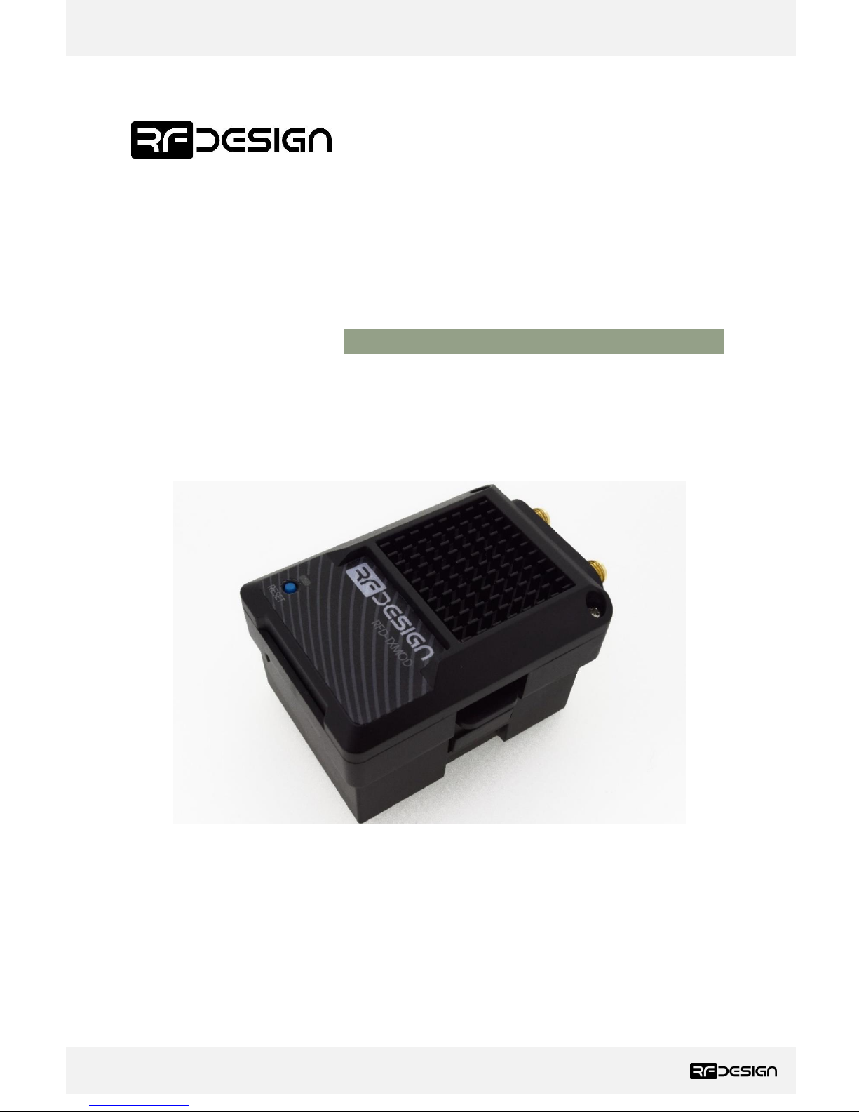
RFD TX Module
User’s Manual
RFDesign Pty Ltd
7/1 Stockwell Place
Archerfield, QLD 4108
rfdesign.com.au
Page 2
RFD TX Module User Manual
www.rfdesign.com.au
1
Version 1.0 Last update 07/03/2019
Table of contents
1 Introduction .................................................................................................................................... 2
1.1 Product Description ................................................................................................................ 2
1.2 Getting to know the product .................................................................................................. 2
2 RC – TX Module Compatibility ........................................................................................................ 4
3 Getting Started ................................................................................................................................ 5
3.1 Radio Controller Configuration ............................................................................................... 5
3.2 TX Module Configuration ........................................................................................................ 5
3.2.1 Configuration Webpage .................................................................................................. 6
3.2.2 WiFi Configuration .......................................................................................................... 6
3.2.3 TX Module Internal RFD900x Modem settings ............................................................. 11
3.3 Vehicle Modem ..................................................................................................................... 17
4 Ground control station software .................................................................................................. 18
5 Antenna Recommendation ........................................................................................................... 19
6 Technical Specifications ................................................................................................................ 20
6.1 TX Module Power Consumption ........................................................................................... 20
6.2 Modem Specification ............................................................................................................ 20
6.3 WiFi Specifications ................................................................................................................ 21
6.4 Radio Controller Interface..................................................................................................... 22
6.5 Physical Dimensions .............................................................................................................. 22
7 Useful Links ................................................................................................................................... 23
8 Revision History ............................................................................................................................ 24
Page 3
RFD TX Module User Manual
www.rfdesign.com.au
2
Version 1.0 Last update 07/03/2019
1 Introduction
1.1 Product Description
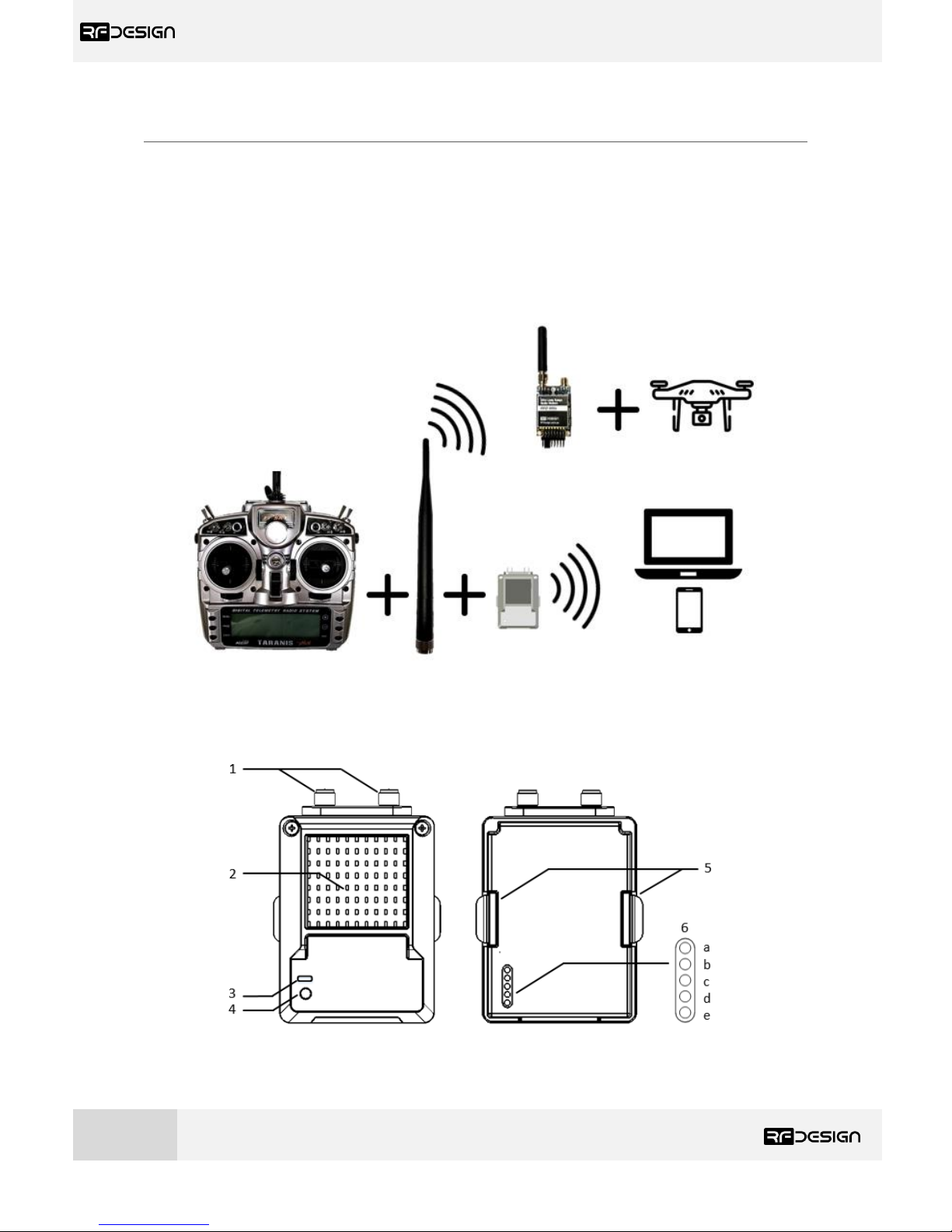
The RFD TX Module has been designed to work in conjunction with the Taranis X9D Radio Controller
(RC) from FrSky and other compatible controllers. The RFD TX Module transmits the PPM stream from
the controller to the vehicle via the RF Design long range telemetry modems while also receiving
telemetry data received from the aircraft which can be broadcast to a computer or smart device
through the TX Module’s built in WiFi module.
1.2 Getting to know the product
Figure 2 - TX Module Part Description
Figure 1 - Typical Application Diagram.
*Components not to scale
Page 4
RFD TX Module User Manual
www.rfdesign.com.au
3
Version 1.0 Last update 07/03/2019
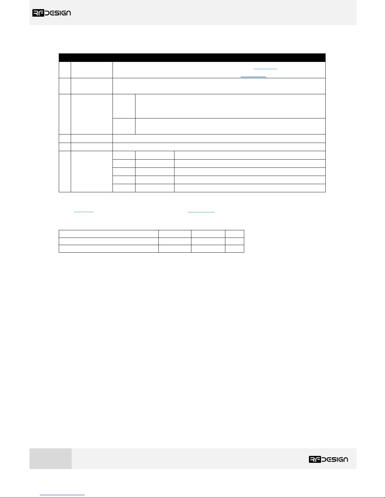
Table 1 - TX Module Description
# Description /Note
1
Antenna
connectors
For further information about the antennas, refer to section 5 in this document
or to the RFD 900x Modem datasheet linked in section 7.
2
Heat sink
The heatsink, visible through the top cover is required for proper operation and
should not be covered while the unit is in use.
3
Status LEDs
Red
Blinks slowly a few times - indicates establishing link to a WiFi client.
Blinks rapidly for some time - flashing the modem firmware
Solid - device initialisation has completed
Green
Blinking – RFD modem looking for a link
Solid – RFD modem bound to another modem
4
Button
Press 5 times within 5 seconds to reset all WiFi settings to default values.
5
Tabs
To lock the TX Module into the radio control socket.
6
RC and
TX Module
Interface. ∗
a
PPM
Sends RC data into TX Module.
b
+6 V
6V supply positive terminal (not used by the module)
c
+Bat
Positive battery terminal (supply for the module)**
d
GND
Ground
e - Not connected
∗Interface between RC and TX Module is done through a female 0.1” pitch connector.
**
See Table 2 below for module supply ratings and section 6.1 for the relation between battery voltage and
current draw with different battery types.
Table 2 - TX Module Supply Ratings
Parameter
Minimum
Maximum
Units
Supply Voltage (+Bat relative to GND)
+5
+18
V
Operating Current Draw
N/A
1.2*
A
∗Rating for TX Module with RFD modem set for maximum 1W transmit power measured at 5V supply.
Page 5
RFD TX Module User Manual
www.rfdesign.com.au
4
Version 1.0 Last update 07/03/2019
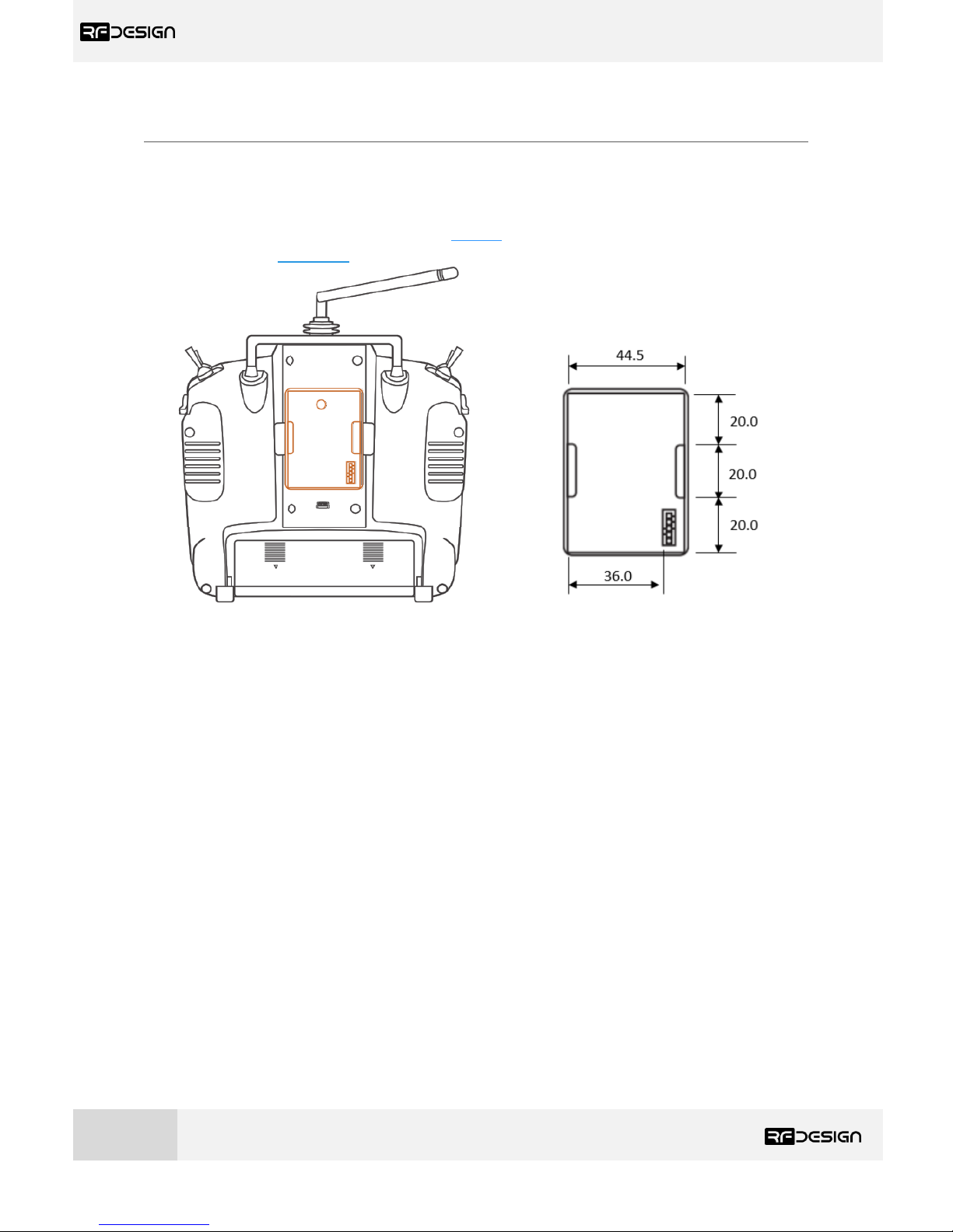
2 RC – TX Module Compatibility
The TX Module has been designed to fit into the rear expansion bay of an FrSky Taranis X9D Plus.
However, it might be compatible with other transmitters. To ensure compatibility, check that the
dimensions of the slot and the pin configuration of the connector at the back of your RC match those
specified for the module in this section and Table 1. For detailed information on the TX Module
dimensions refer to section 6.5.
Figure 3 - RC External RF module slot dimensions.
Page 6
RFD TX Module User Manual
www.rfdesign.com.au
5
Version 1.0 Last update 07/03/2019
3 Getting Started
The RFD TX Module has five elements requiring configuration before operating.
- Radio Controller (RC) configuration
- TX Module Wi-Fi access configuration
- TX Module RFD900x Radio Configuration
- Vehicle (paired) RFD 900x modem configuration
- Ground Control Station (GCS) configuration
3.1 Radio Controller Configuration
a) Enable PPM mode on radio controller
The TARANIS X9D PLUS radio controller (RC) is used as a guide to describe this section. For specific
instructions on activating this mode on other RCs refer to the manufacture’s manual for the device.
Please check for transmitter - RFD TX Module compatibility and ensure it supports the same interface
pinout specified in Table 1 and physical dimensions described in section 2 and section 6.5.
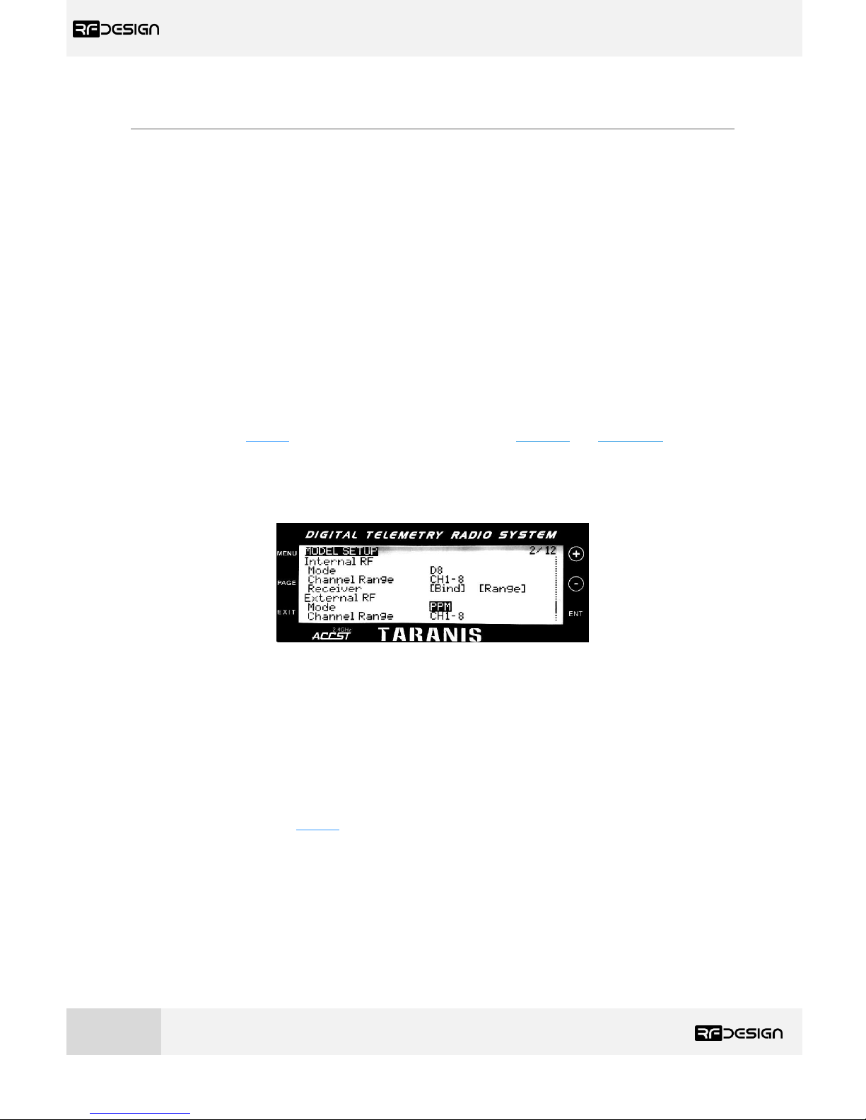
For a TARANIS X9D PLUS switch on the RC and choose the vehicle you intend to operate. Navigate to
the Model Setup submenu and scroll down until you find the External RF configuration section, as
shown in figure 4, then choose “Mode PPM” to enable external PPM stream for the TX Module.
Figure 4 - PPM mode configuration on TARANIS X9D PLUS RC.
3.2 TX Module Configuration
With the RC switched off, remove the rear protective cover from the radio controller and insert the
TX Module. Ensure the TX Module is inserted fully into the opening and the two tabs have locked the
in place.
Switch on and observe the TX Module’s LEDs. The red LED will blink and then go solid during the
power up sequence, as per Table 1, and the green LED will indicate the state of the modem link.
The communication settings for both the WiFi and RFD telemetry links are described below.
Page 7
RFD TX Module User Manual
www.rfdesign.com.au
6
Version 1.0 Last update 07/03/2019
3.2.1 Configuration Webpage
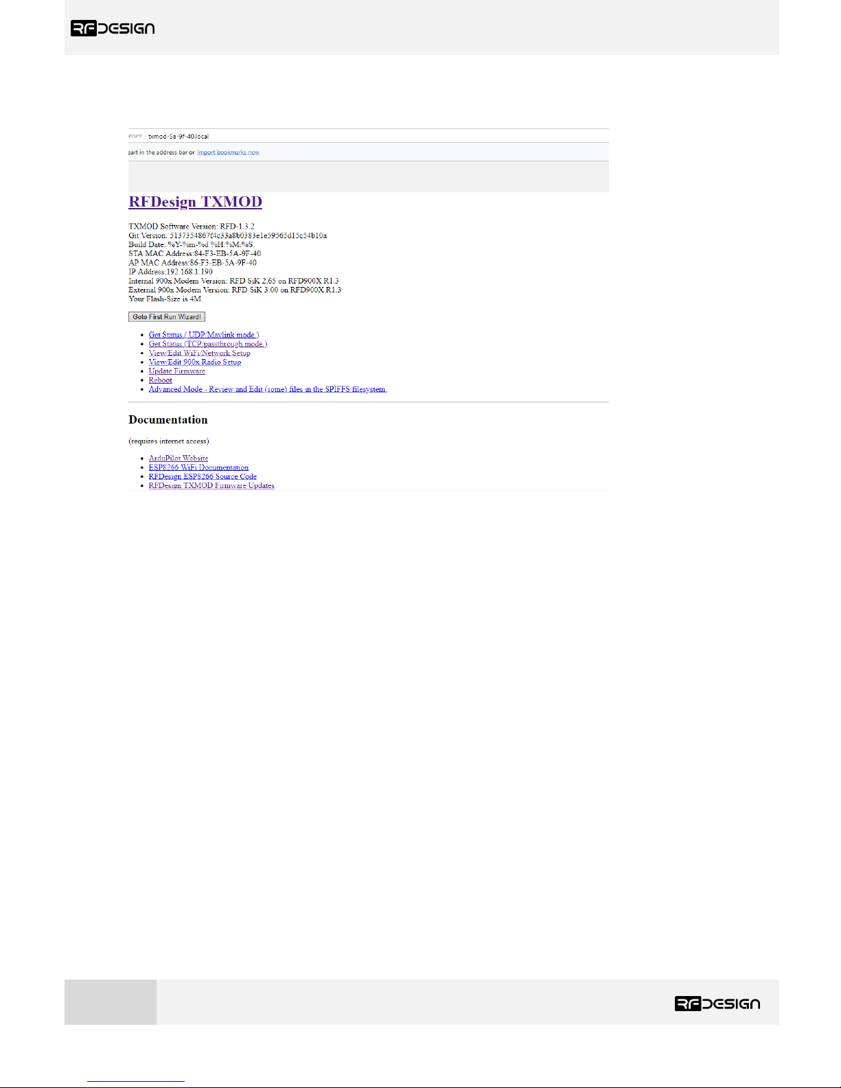
Figure 6 Configuration home page
The configuration home page provides basic information on the RF Design TX module, such as
software versions and MAC and IP addresses, as well as links to the various configuration pages. It can
be accessed by directly addressing the IP address of the module, by default in access point (AP) mode
this is 192.168.4.1, in a web browser. Alternatively, it can be accessed by the address http://TXMODXX-XX-XX.local where the Xs are the same as the Xs in the access point network name i.e. the last 6
digits of the MAC address. It should be noted that this will require the installation of some support
software for correct operation, for detail please see section 3.2.2 d) TX module as station.
3.2.2 WiFi Configuration
An active WiFi connection is used to configure the TX Module. On first power up, the TX Module will
default to Access point mode, with SSID of the format ‘TXMOD-XX-XX-XX’, where the XX are unique
hexadecimal characters relating to the unit MAC address.
a) Connect to TX Module Access Point
Use your computer or smart device to search for and connect to the access point WiFi network
generated by the TX Module (use ‘txmod123’ as default password). It may be necessary to disable
mobile data on tablets and phones to force the browser to use the TX Module network.
Page 8
RFD TX Module User Manual
www.rfdesign.com.au
7
Version 1.0 Last update 07/03/2019
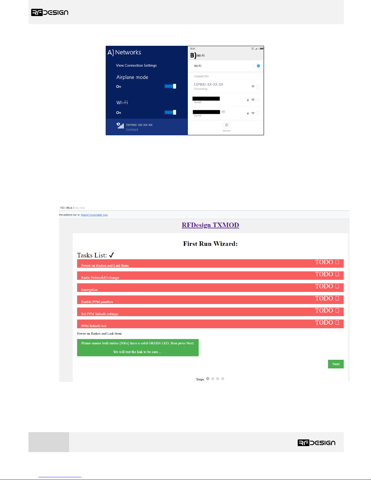
Figure 7 - Network settings. A) Windows 8.1. B) Android.
b) First run wizard
The easiest way to set up your TX Module for its initial use is with the First Run Wizard from the
home page. See figure 6.
The wizard, see figure 8, will guide you through several steps for getting your module configured for
use.
Figure 8 - First run wizard
c) Change Network Settings
Page 9
RFD TX Module User Manual
www.rfdesign.com.au
8
Version 1.0 Last update 07/03/2019
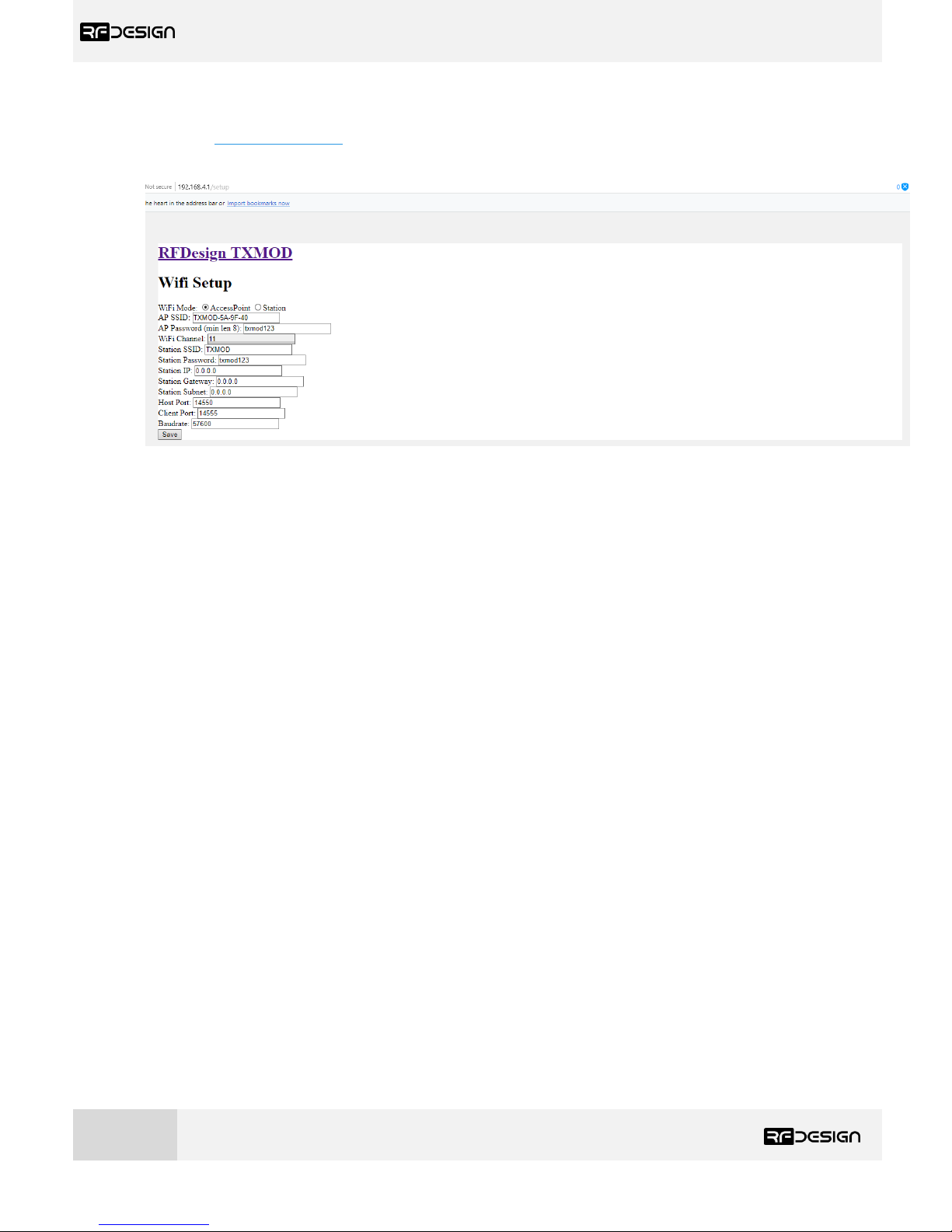
To change the SSID or password, open a web browser and enter the module’s IP address by default in
AP mode http://192.168.4.1/ This will display the TX Module configuration. To change the WiFi
settings click on ‘Edit WiFi/Network Setup’ to access the WiFi setup interface of figure 9.
Figure 9 -WiFi settings configuration page.
Page 10
RFD TX Module User Manual
www.rfdesign.com.au
9
Version 1.0 Last update 07/03/2019
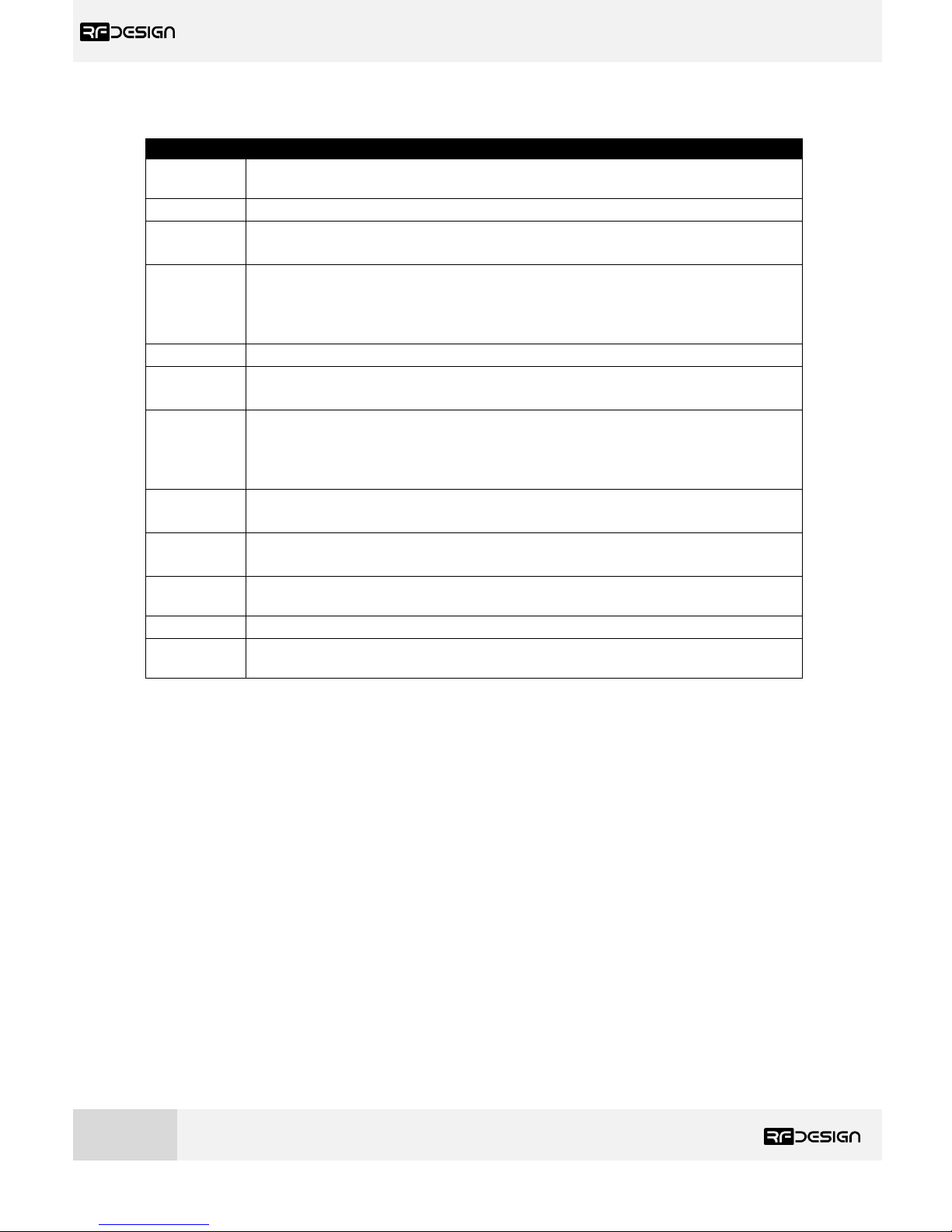
Table 2 - WiFi Settings Description
Parameter
Description
WiFi mode
This sets the module to act as an access point (default) or as a station on an existing
access point, such as a home network.
AP SSID
Is the SSID used for creating the access point.
AP
Password
This is the password that will be used for the access point. It must be a minimum of
8 character long
WiFi
Channel
Allows the user to set the channel as per the WiFi 802.11 standard definitions this
can be used as needed to prevent interference or meet the requirements of the
network that the module is joining. The default is channel 11 a part of the most
commonly used channel set of 1, 6 and 11.
StationSSID
The SSID of the network that the TX Module should attempt to join.
Station
Password
The password of the network that the TX Module should attempt to join.
Station IP
The static IP address to assign the TX Module when joining the network. (Note this
may require appropriate settings to be made on the network router. Once assigned
as a station the landing page for the TX Module settings becomes the Station IP
address that was assigned.)
Station
Gateway
The Gateway IP address of the network that the TX Module should attempt to join.
Station
Subnet
The Subnet Mask of the network that the TX Module should attempt to join as a
station.
Host Port
This is the UDP host port number. This is the port that you will direct a connection
to in UDP mode
Client Port
This is the UDP client port number.
Baudrate
Baudrate of the serial link with the modem. It must match the modem serial speed
setting to allow the two to communicate.
After changing the desired settings, press save. To finalise the changes power cycle the transmitter.
Note that changes to the network settings may result in you needing to change the WiFi connection
that you use in order to connect to the module e.g. selecting the new WiFi name or force the system
to forget an old password then enter the new one.
d) TX Module as a station
To use the TX Module on an existing WiFi network to provide telemetry data to a GCS while still
allowing access to the internet, for example to download maps, there are a couple of possible
implementations.
Basic users
For Windows and Linux users this will require the installation of some support software Bonjour
Services from Apple for Windows (https://support.apple.com/kb/DL999?locale=en_US) and Avahi for
Linux. Windows users may also need to use to use Chrome (or Chrome based) browser as this has
good support for the Apple software.
Once this has been installed connect to the TX Module in default AP mode go to WiFi settings and
choose ‘Station’ in ‘WiFi Mode’, set the correct SSID (in StationSSID) and password of the network in
Page 11
RFD TX Module User Manual
www.rfdesign.com.au
10
Version 1.0 Last update 07/03/2019
“Station Password”, leave “Station IP”, “Station Gateway” and “Station Subnet Mask” as 0.0.0.0 then
press “Save” and finally reboot the device. You can connect the to the WiFi network with the TX
Module on it then open the browser and enter the following address http://TXMOD-XX-XX-XX.local
where the Xs are the same as the Xs in the access point network name.
Advanced users
The module must be set up by choosing ‘Station’ in ‘WiFi Mode’, set the correct SSID (in StationSSID)
and password of the network in “Station Password”.
You will need to find the Gateway and Subnet mask of the network then to write the appropriate
values in ‘Station Gateway’, ‘Station Subnet’. Assigning the ‘Station IP’ requiring that a static IP is set
on the DHCP server, normally the network router, this is so the device will be at a known address on
the network allowing for the user to connect using this new fixed IP in place of the 192.168.4.1 of
access point mode. Network information such as the Subnet Mask and Gateway address can be found
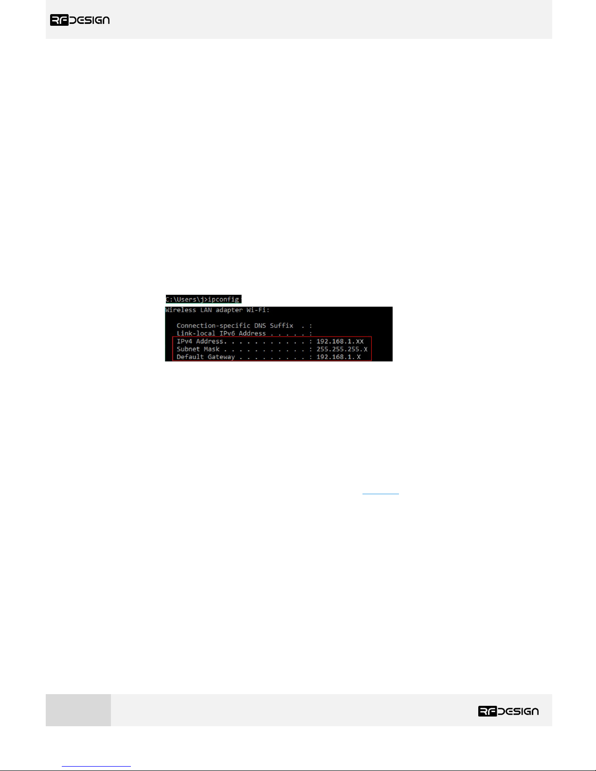
on a network connected device. For instance, in windows launch a command prompt, type ‘ipconfig’
and press enter. Information similar to figure 10 will be shown. In linux based devices typing ‘ifconfig’
to the terminal should give similar results.
Figure 10 – Command Prompt.
Default Gateway ->‘Station Gateway’
Subnet Mask ->‘Station Subnet’
e) Firmware Update:
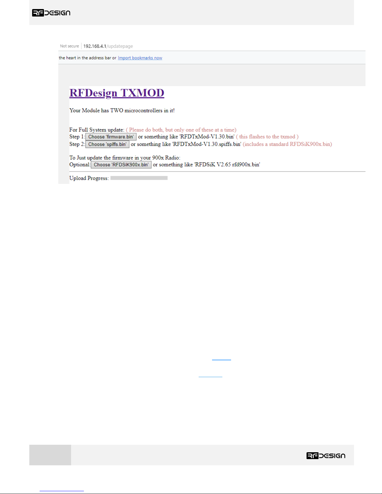
To update the WiFi firmware on the TX Module, follow the links in section 7 to find and download the
required firmware version. Then, on the browser configuration landing page, as per figure 7, select
‘Update Firmware’. Updating the WiFi interface uses two different files; the ESP8266 ‘firmware.bin’
and the ‘spiffs.bin’ files. These files should not be uploaded and flashed simultaneously. Click first on
the ‘Choose File’ button in the ESP8266 section, then on ‘Update & Reboot’ and follow on-screen
instructions. See figure 11 below. After that, proceed to upload the ‘spiffs.bin’ file by selecting it using
the ‘Choose File’ button and then on ‘Update SPIFFS’ at the very bottom section of the page. Follow
commands and you’ll have successfully updated the WiFi firmware on the TX Module.
Page 12
RFD TX Module User Manual
www.rfdesign.com.au
11
Version 1.0 Last update 07/03/2019
Figure 11 TX Module update page
f) WiFi Troubleshooting:
If you forget your settings or the device is not available on the network, it is possible to reset the
module to its default settings by pressing the button 5 times rapidly. It can then be accessed using the
default settings.
In some cases, user connection settings may prevent devices from accessing the WiFi addresses. It
may therefore be necessary to do some basic troubleshooting such as removing the existing network
settings from device memory, resetting the wireless adaptor, turn off mobile data and disconnect
other networking devices such as LAN cables. In other cases, running the Windows Network
Diagnostics may help.
3.2.3 TX Module Internal RFD900x Modem settings
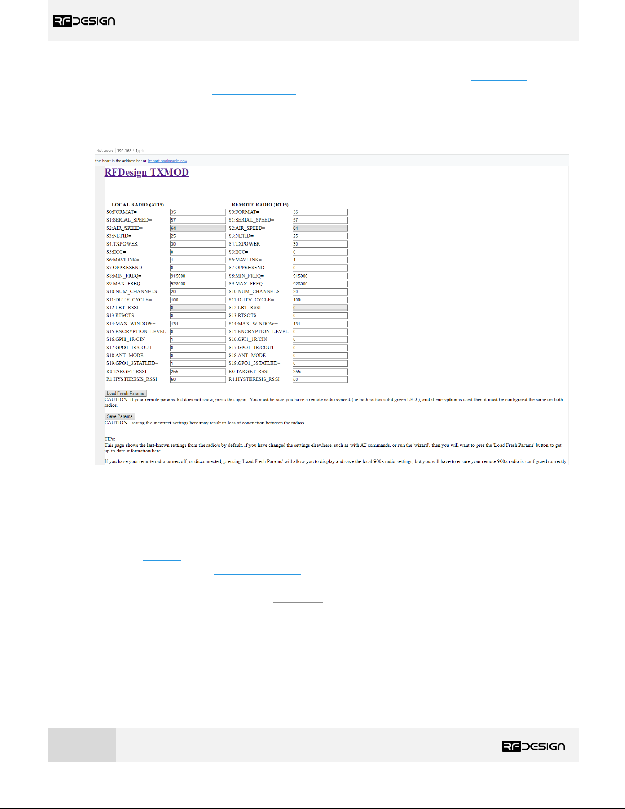
The TX Module has an RFD900x series modem internally pre-configured with the parameters of
figure 12. A description of this parameters can be found in Table 3 - RFD900x parameters. For further
information regarding the internal modem refer to the RFD900x Peer to Peer Firmware and RFDesign
Modem 900x Datasheet documents using the links in section 7.
These internal settings and the settings of any paired modem can be modified using several methods
which will be described throughout this section
- Through the module web interface under ‘Edit 900x Radio Setup’
- Using TCP link and the RFD modem tools
- Using TCP or UDP link and Mission Planner (MP) Sik Radio page
Page 13
RFD TX Module User Manual
www.rfdesign.com.au
12
Version 1.0 Last update 07/03/2019
- Using a Telnet compatible serial terminal programme such as putty 1
Notes:
1
This method is for advanced users and involves setting modem AT and RT commands via a remote terminal as such the exact method is
not included in this document.
When setting up the power level and the frequency band, please check the radiofrequency spectrum
plan in your area to operate in compliance with its legislation.
In order to avoid communication incompatibilities, it is important that both the TX Module modem
and the vehicle modem have the same firmware version and it is v2.55 or higher of the RFD SiK.
Uploading the firmware onto the TX Module modem is covered in this section; how to update the
firmware onto the vehicle modem, is covered in section 3.3 and the modem datasheet in the useful
links of section xxxx
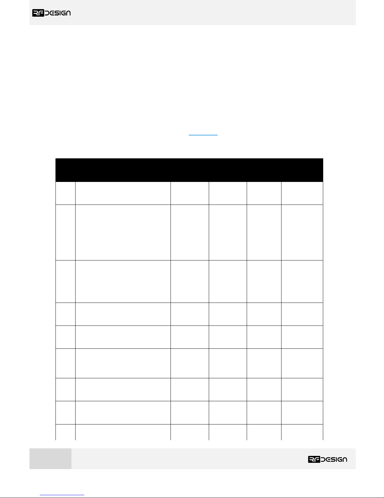
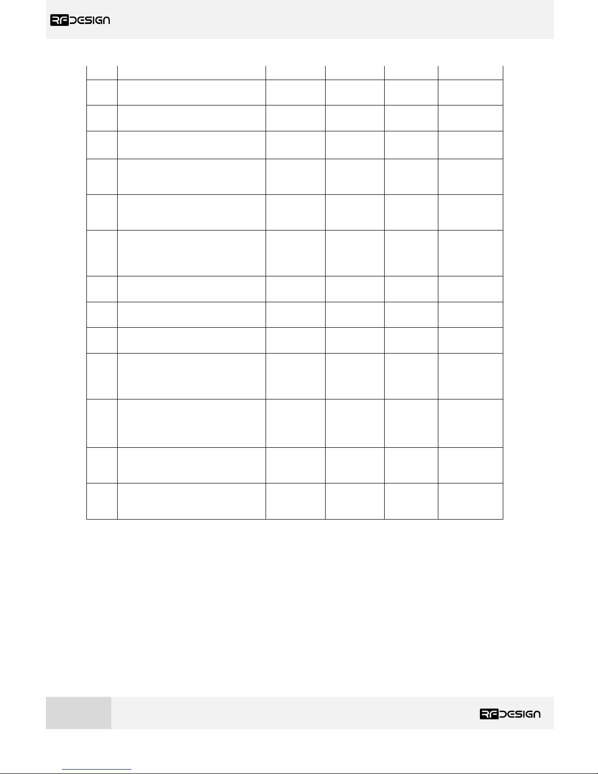
Table 3 - RFD900x parameters
Reg
#
S Register
Description
Default
Value
Maximum
Value
Minimum
Value
Must be the same
at both ends of
the link?
S0
FORMAT
This is for EEPROM version, it should not
be changed. It is set by the firmware
Firmware
dependant
N/A
N/A
No
S1
SERIAL_SPEED
Serial speed in ‘one-byte form’.
Accepted values are 1, 2, 4, 9, 19, 38, 57,
115, 230, 460 corresponding to 1200bps,
2400bps, 4800bps, 9600bps, 19200bps,
38400bps, 57600bps, 115200bps,
230400bps, 460800bps and 1000000bps
respectively.
57
10003 1 No
S2
AIR_SPEED
Air data rate in ‘one-byte form’.
Accepted values are 4,64,125,250,500,
750 corresponding to 4000bps,
64000bps, 125000bps, 25000bps,
500000bps and 750000bps respectively.
64
7503 4 Yes
S3
NETID
Network ID. The same on both modems
in the pair
25
255 0 Yes
S4
TXPOWER
Transmit power in dBm. Maximum is
30dBm
30
30 0 No
S5
ECC1
Enables or disables the Golay error
correcting code. When enabled, it
doubles the over-the-air data usage
0 1 0
Yes
S6
MAVLINK2
Enables or disables the MAVLink framing
and reporting
1 1 0
No
S7
OP_RESEND
Opportunistic resend allows the node to
resend packets if it has spare bandwidth
0 1 0
No
S8
MIN_FREQ
915000
/8680004
927000
/8690004
902000
/8680004
Yes
Page 14
RFD TX Module User Manual
www.rfdesign.com.au
13
Version 1.0 Last update 07/03/2019
Min frequency in KHz
S9
MAX_FREQ
Max frequency in KHz
928000
/8690004
928000
/8700004
903000
/8690004
Yes
S10
NUM_CHANNELS
Number of frequency hopping channels
20
50 1 Yes
S11
DUTY_CYCLE
The percentage of time to allow transmit
100
100
10
No
S12
LBT_RSSI
Listen before talk threshold
(This parameter shouldn’t be changed)
0
220
25
Yes
S13
RTSCTS
Ready-to-send and Clear-to-send flow
control.
0 1 0
No
S14
Max Window
Max transit window size used to limit
max time/latency if required otherwise
will be set automatically
131
400
20
Yes
S15
Encryption Level
Encryption level 0=off, 1=128bit AES
0 1 0
Yes
S16
R/C input GPIO1.1
Set GPIO 1.1 as R/C(PPM) input
0 1 0
No
S17
R/C output GPIO1.1
Set GPIO 1.1 as R/C(PPM) output
0 1 0
No
S185
ANT_MODE
0= Diversity, 1= Antenna 1 only, 2=
Antenna 2 only, 3= Antenna 1 TX and
antenna 2 RX
0 3 0
No
S195
PKT_DROP_RSSI
Sets a RSSI threshold below which the
packet will be discarded. 0 disables the
feature
0
255 0 No
R0
TARGET_RSSI
Optimal RSSI value to try to sustain (255
disables the feature)
255
50
255
No
R1
HYSTERESIS_RSSI
Amount of change before power levels
altered
50
20
50
No
Table 3: RFD900x SiK firmware parameters
Notes:
1
ECC - Software Detection and correction, extra packet information, twice the packet length, is sent to allow the recovery of corrupted
packets.
2
Injects RSSI packet when MAVLink protocol used and heartbeat packet detected.
3
Maximum from version 2.60 onwards
4
868 modems
5
Introduced in V2.55
a) Modifying parameters with the TX Module web interface
Page 15
RFD TX Module User Manual
www.rfdesign.com.au
14
Version 1.0 Last update 07/03/2019
Point your preferred browser to the module’s IP address (if not changed as described in Section 3.2.2,
by default in AP mode it is http://192.168.4.1/) to access the TX Module web interface of figure 8-A.
Click on ‘Edit 900x Radio Setup’ to access the modem’s setup interface of figure 8-B. If the TX Module
has not been paired yet with any other modem, the remote side will appear empty and the message
“Sorry no parameters available” will be shown.
Figure 12 - TX Module modem configuration page.
Settings can be refreshed using the ‘Load Fresh Params’ button. Parameters can be adjusted in the
text boxes as required and then applied by means of the ‘Save Params’ button.
To flash a new firmware, first download the required version of the peer to peer SiK firmware using
the links in section 7. Do not flash the TX Module with a version below v.2.55. Then, point your browser
to the modules IP address (http://192.168.4.1/ by default in AP mode) and on the landing page click
on ‘Update Firmware’ and follow the on-screen instructions to finish the process. To update the
firmware on the vehicle modem, refer to section 3.3.
Page 16
RFD TX Module User Manual
www.rfdesign.com.au
15
Version 1.0 Last update 07/03/2019
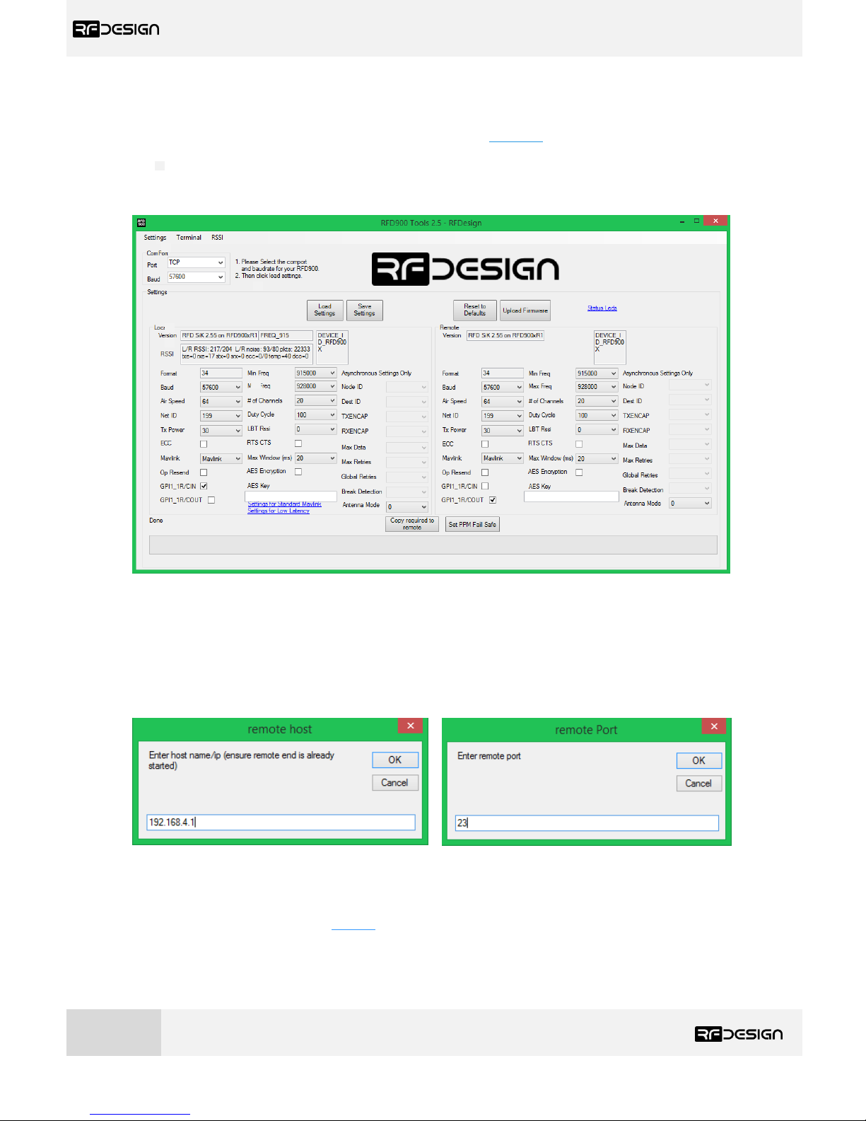
b) RFD900 Tools
The software and manual can be found through the links in section 7. Download the latest version of
the RFD900 Tools, save the *.zip file in your computer, extract it and install the setup.exe file. Please
note that this software is currently only available for windows. Run through the installation process
and launch it. The interface, see figure 13, should pop up.
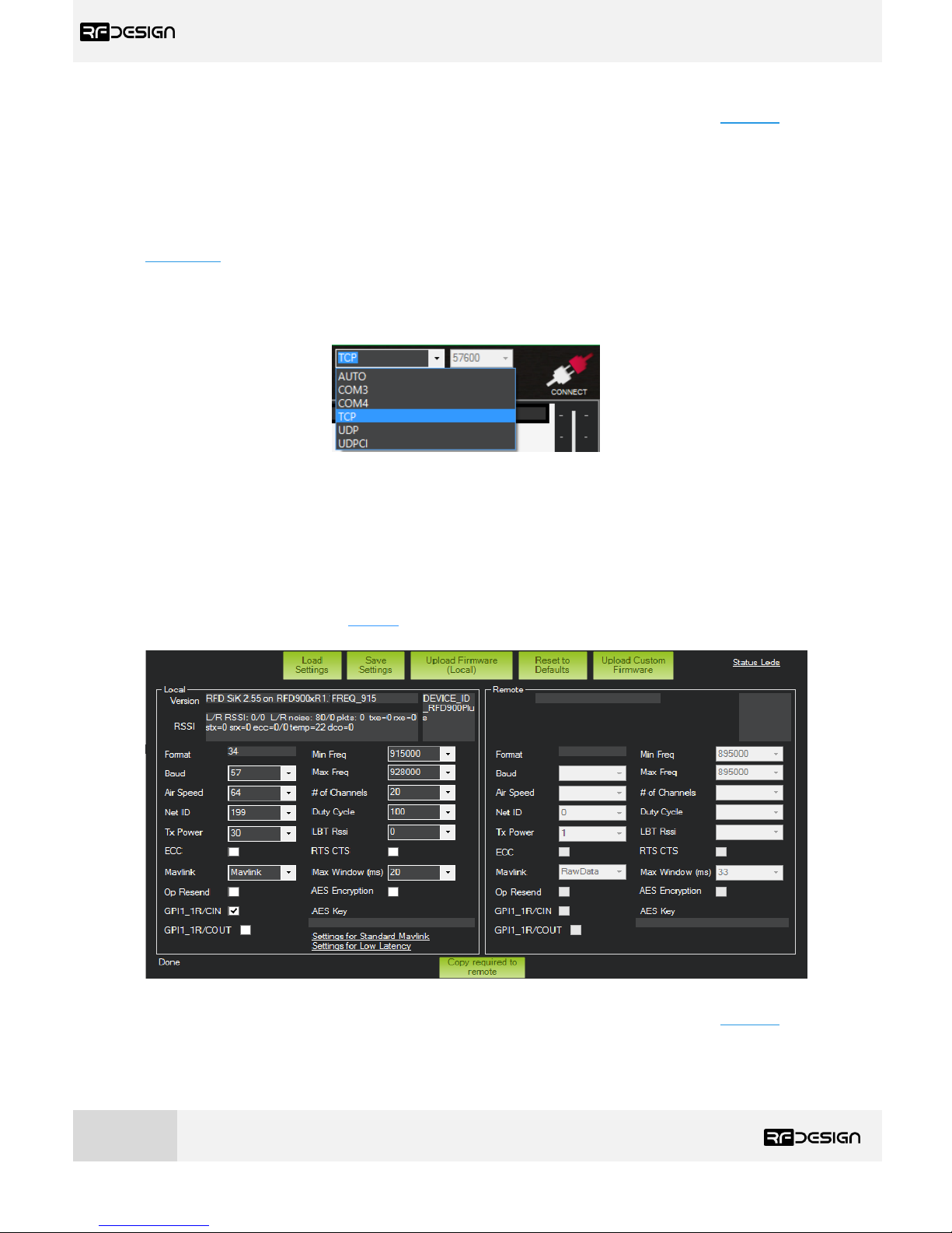
Figure 13 - TX Module modem configuration on RFD900 tools.
Connect your computer to the network with the TX Module on it. Then choose Transmission Control
Protocol (TCP) in the port field and leave the ‘Baud’ field as default. Press connect and fill in the popup boxes with the TX Module IP address, by default in AP mode 192.168.4.1, and the TCP port number,
by default is 23, as per figure 14.
Figure 14 - Remote host and remote port configuration prompts on RFD900 tools.
Now you can use the ‘Load Settings’ button to display the current modem settings. After changing the
desired parameters described in Table 3 - RFD900x parameters, press on ‘Save Settings’ buttons to
upload them onto the modem. A message at the bottom of the page saying “Done” will indicate the
parameters have been saved successfully.
Page 17
RFD TX Module User Manual
www.rfdesign.com.au
16
Version 1.0 Last update 07/03/2019
To flash a new firmware, first download the latest version of firmware using the links in section 7. Do
not flash the TX Module with a version below v.2.55 SiK. Click on the ‘Upload Firmware’ button and
select the *.bin file. The message “Programming firmware into device” will show up at the bottom of
the page. Wait until the process finishes (full green bar and “Programmed firmware into device), then
power cycle the TX Module. The firmware has been successfully flashed into your device.
This process does not allow flashing the firmware onto the remote modem. To do so, refer to
section 3.3.
c) Mission Planner
Choose TCP or UDP from the drop-down menu and press ‘CONNECT’ button as per figure 13.
Figure 15 – Mission planner connection options.
As with the modem tools you will need to enter the IP address, by default in AP mode 192.168.4.1,
and port number in the pop-up boxes, see figure 12. TCP port number is 23 and UDP is set in WiFi
settings, by default it is 14550.
Go to Initial Setup/Optional Hardware/Sik Radio section as seen in the screenshot in figure 16 and
click on Load Settings button. You can then use the drop-down boxes and buttons to manage the
modem settings described in Table 3 - RFD900x parameters. Press ‘Save Settings’ to upload the
changes to the modem.
Figure 16 - Modem configuration on Mission Planner.
To flash a new firmware, first download the latest version of firmware using the links in section 7. Do
not flash the TX Module with a version below v.2.55 SiK. Then click on ‘Upload Firmware (Local)’ and
choose the *.bin file you just downloaded. Wait until the process finishes (a message will appear at
Page 18
RFD TX Module User Manual
www.rfdesign.com.au
17
Version 1.0 Last update 07/03/2019
the bottom of the page) and reboot the TX Module. You have successfully updated the firmware. To
update the firmware on the vehicle modem, refer to section 3.3.
3.3 Vehicle Modem
The modem chosen on the vehicle side should be an RFD900x and should be flashed to the same
firmware version than the one in the TX Module and it should be higher than v2.55 in order to ensure
proper communication.
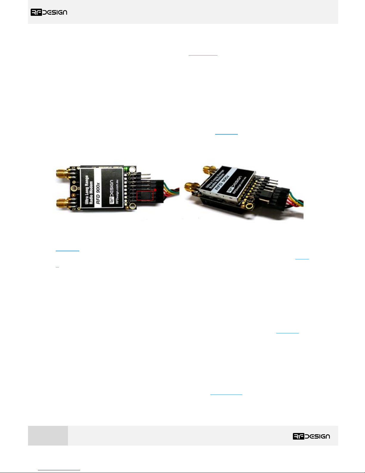
Initial configuration of the vehicle modem should be done connecting an FTDI cable as per figure 17.
The black cable of the FTDI, i.e. pin 1, should connect to pin 1 on the modem, and using the RFD tools
or a serial terminal programme, download links can be found in section 7, the settings can be applied.
This is required when pairing with a new modem not supplied with the kit, as the default settings of a
new modem will not match with the TX module modem, or after changing TX Module modem setting.
A jumper between pins 2 and 3 on the top row is necessary when powering the modem from the FTDI.
Figure 17 - Modem connected to FTDI cable (pins 1,3,5,7,9,11) to enable serial communications. *Jumper (pins 4&6).
To configure the modem using the RFD900 tools, download and install the software using the links on
section 7 if it is not installed on your computer yet. Launch the programme and the configuration
interface of figure 13 should pop-up. Use this interface to configure the parameters described in Table
3 - RFD900x parameters. When connected directly through the FTDI cable the vehicle modem will
appear as local.
An important setting on the vehicle modem is to set modem GPIO1.1 as a PPM output. This allows the
modem pin 15 to output the PPM stream received from the TX Module modem. To enable this, check
the ‘CPI1_1R/COUT’ box in any and ensure ‘CPI1_1R/CIN’ is unchecked (on the TX Module modem this
is already set the other way around by default). Then save the settings to upload the configuration
onto the modem.
To flash a new firmware, first download the latest version of firmware using the links in section 7. Do
use a version below v.2.55. Then on RFD900 tools click on ‘Upload Firmware (Local)’ and choose the
*.bin file you just downloaded. Wait until the process finishes (a message will appear at the bottom
of the page) and reboot the TX Module. You have successfully updated the firmware.
After the modem has been configured correctly it will be able to link with the TX Module modem,
indicated by a solid green LED on both devices. From this point onwards the FTDI cable is no longer
needed to configure the vehicle modem. Instead this can be done over the air via the TX Module using
the remote modem settings any of the methods described in section 3.2.2. This only works while the
modem in the vehicle and TX Module are linked as indicated by a solid green LED.
Page 19
RFD TX Module User Manual
www.rfdesign.com.au
18
Version 1.0 Last update 07/03/2019
4 Ground control station software
Once the modem and WiFi communications are configured it is possible to use the telemetry data
stream. The example software used in this section is Mission Planner for Windows and Tower for
Android. However, this process can be extrapolated to other software supporting Transmission
Control Protocol (TCP) or User Datagram Protocol (UDP).
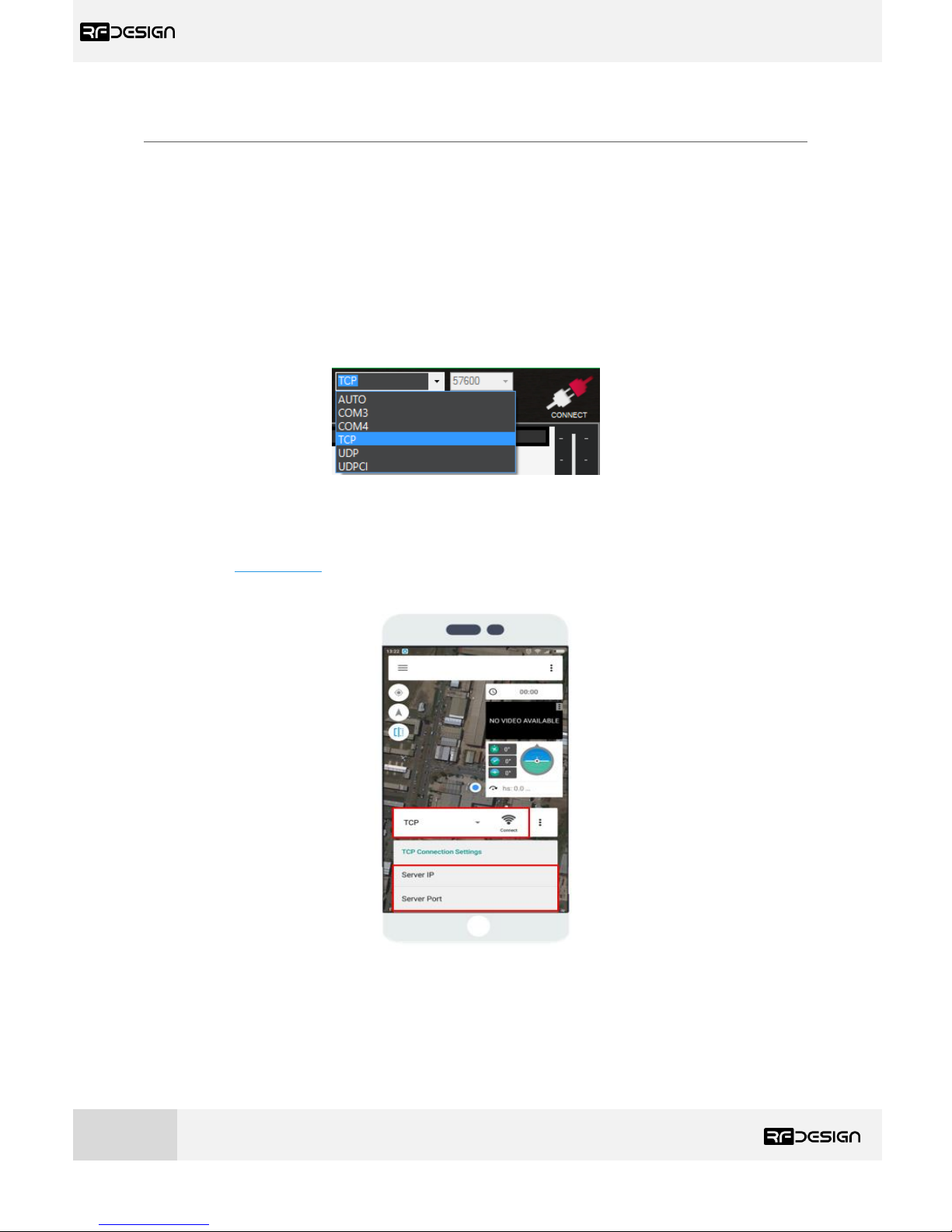
Connect your computer or smart device to the configured WiFi network; that is either the TX Module
Access Point or the linked network when using the module as a station. Then open Mission Planner
on your computer or Tower App on your Android device and choose TCP or UDP and press the button
“CONNECT” as per figure 18.
Figure 18 – Mission planner connection options.
Then, when asked for, enter the IP address and port number in the pop-up boxes. Default values in AP
mode are IP 192.168.4.1, TCP port number 23 and UDP 14550. After that, if properly connected,
telemetry data should be available, and the control software should run missions as normal.
Figure 19 - Tower configuration on Android.
Page 20
RFD TX Module User Manual
www.rfdesign.com.au
19
Version 1.0 Last update 07/03/2019
5 Antenna Recommendation
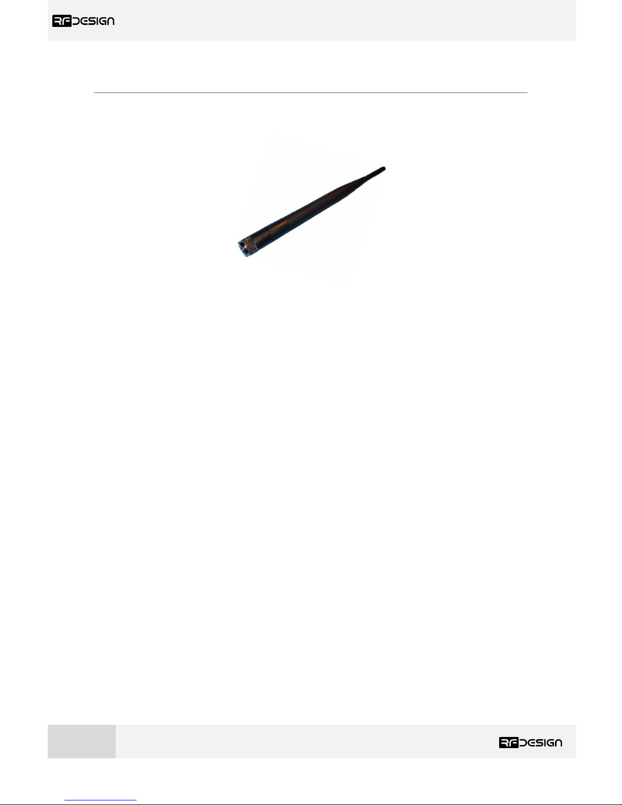
Any antenna with a male RPSMA fitting and matched to the 902-928MHz ISM band can be used
however, the recommended antenna for the TX Module is the 3 dBi half wave dipole which is
provided in the kit and is available for purchase on the RF Design store.
Figure 20 -: 900MHz Half Wave Dipole Antenna 3 dBi.
When assembling/disassembling the TX Module to/from the transmitter, be aware the antenna may
have to be removed then reattached due to mechanical restraints.
Page 21
RFD TX Module User Manual
www.rfdesign.com.au
20
Version 1.0 Last update 07/03/2019
6 Technical Specifications
6.1 TX Module Power Consumption
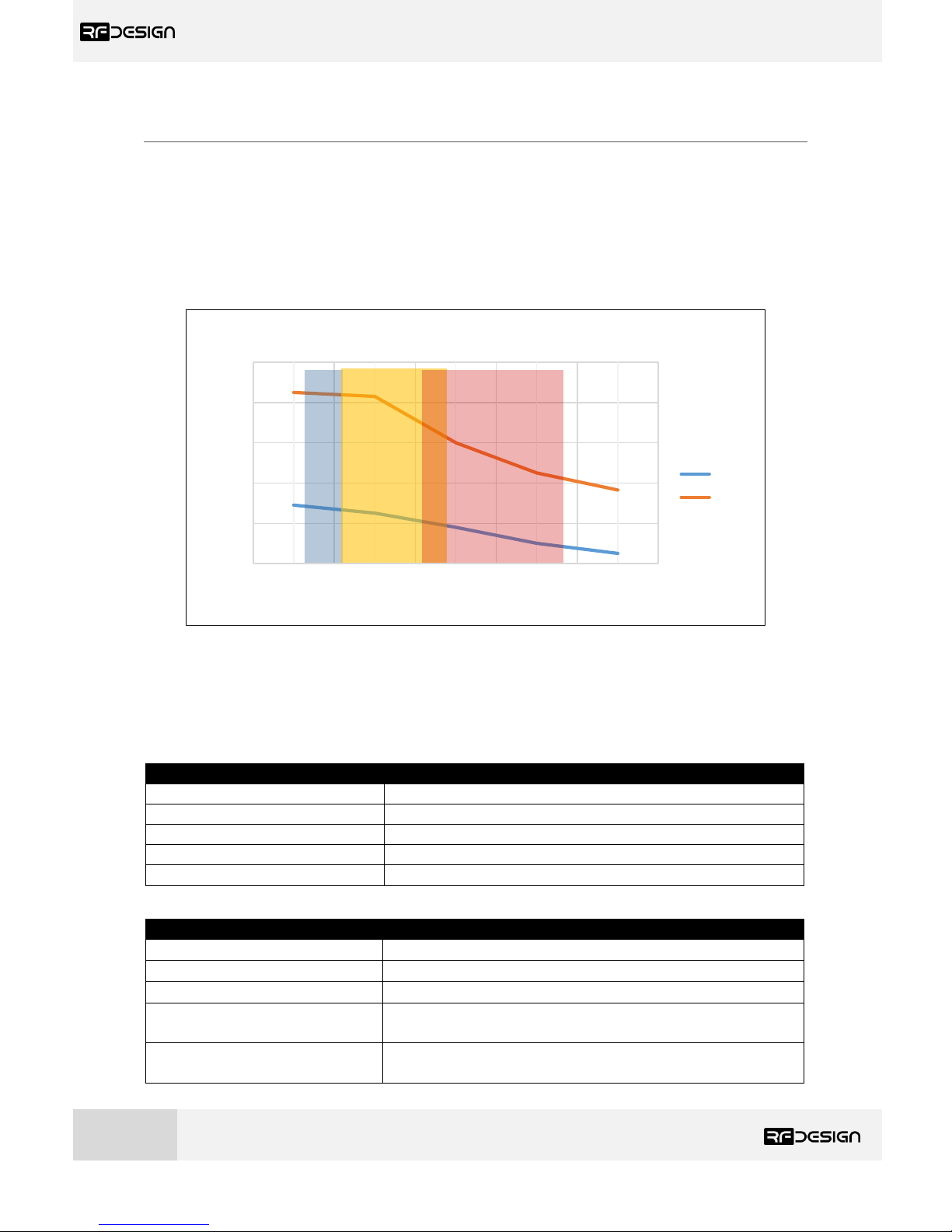
The graph indicates the current consumption of the TX Module vs the supplied battery voltage. It
should be noted that this graph is generated with the RFD modem configured for 30dBm, or 1 W,
transmission. Changing the modem power will significantly affect the current draw. The graph has
been divided to illustrate some common RC battery configurations.
Figure 21 - TX Module current consumption vs RC battery voltage. A) (Blue area) 6S Ni-MH B) (Orange area) 3S LiFe
C) (Red area) 3S LiPo.
6.2 Modem Specification
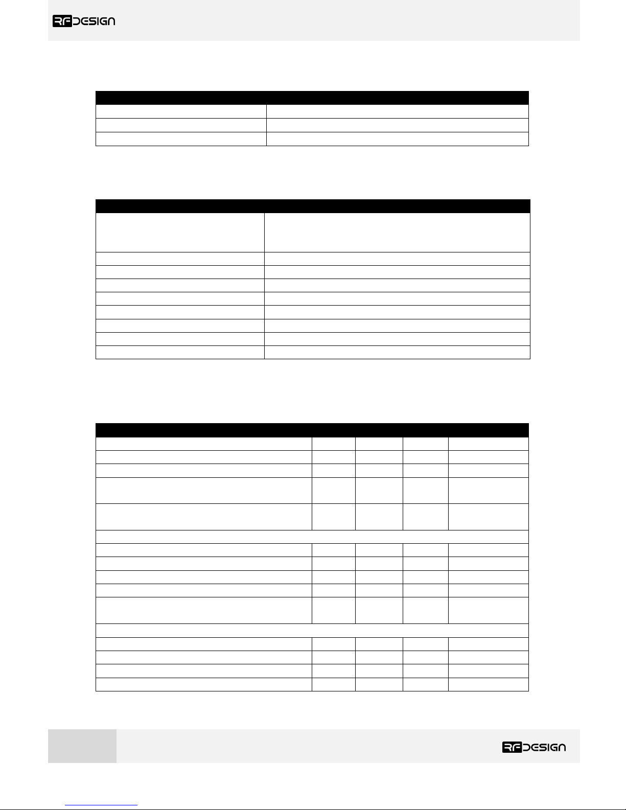
Table 4- Performance
Supported RF Data Rates
4, 64, 125, 250 and 500 kbits/sec
Indoor Range
500 m – 1 km
Line-Of-Sight Range
40km or more depending on antennas
Transmit Power
0 to 30dBm in 1dBm steps
Receiver Sensitivity
>121dBm
Table 5 - Features
Configuration Method
AT Commands, APM Planner, Customized Configuration Tool
Frequency Band
902 MHz – 928 MHz
Interference Immunity
FHSS (Frequency Hopping Spread Spectrum)
Serial Interface Data Rate
1200, 2400, 4800, 9600, 19200, 38400, 57600, 115200,
230400, 450800, 1000000 baud/s
Compliance Standards
0.2
0.4
0.6
0.8
1
1.2
6 8 10 12 14
Current Consumption [A]
Battery Voltage [V]
I_Draw vs V_Bat
I(ave)
I(peak)
Page 22
RFD TX Module User Manual
www.rfdesign.com.au
21
Version 1.0 Last update 07/03/2019
Table 6 - Networking and Security
Addressing Options
Network ID: 0 –255
Channels
Up to 50 Frequency Hopping Channels
Supported Network Topologies
Point to point
6.3 WiFi Specifications
Table 7 - WiFi Parameters
Certificates
FCC
CE 0890
RoHS
WiFi Protocols
802.11 b/g/n
Frequency Range
2.4GHz-2.5GHz (2400MHz-2483.5MHz)
Wi-Fi mode
station/softAP/
Security
WPA/WPA2
Encryption
WEP/TKIP/AES
Firmware Upgrade
OTA (via network)
Network Protocols
IPv4, TCP/UDP/HTTP/FTP
User Configuration
Browser interface
Table 8 – ESP8266 Receiver Characteristics
Parameters
Min
Typical
Max
Unit
Input frequency
2412
2484
MHz
Input impedance
50 Ω
Input reflection
-10
dB
Output power of PA for 72.2Mbps
15.5
16.5
17.5
dBm
Output power of PA for 11b mode
19.5
20.5
21.5
dBm
Sensitivity
DSSS, 1 Mbps
-98 dBm
CCK, 11 Mbps
-91 dBm
6 Mbps (1/2 BPSK)
-93 dBm
54 Mbps (3/4 64-QAM)
-75 dBm
HT20, MCS7 (65 Mbps, 72.2 Mbps)
-72 dBm
Adjacent Channel Rejection
OFDM, 6 Mbps
37 dBm
OFDM, 54 Mbps
21 dBm
HT20, MCS0
37 dBm
HT20, MCS7
20 dBm
Page 23
RFD TX Module User Manual
www.rfdesign.com.au
22
Version 1.0 Last update 07/03/2019
6.4 Radio Controller Interface
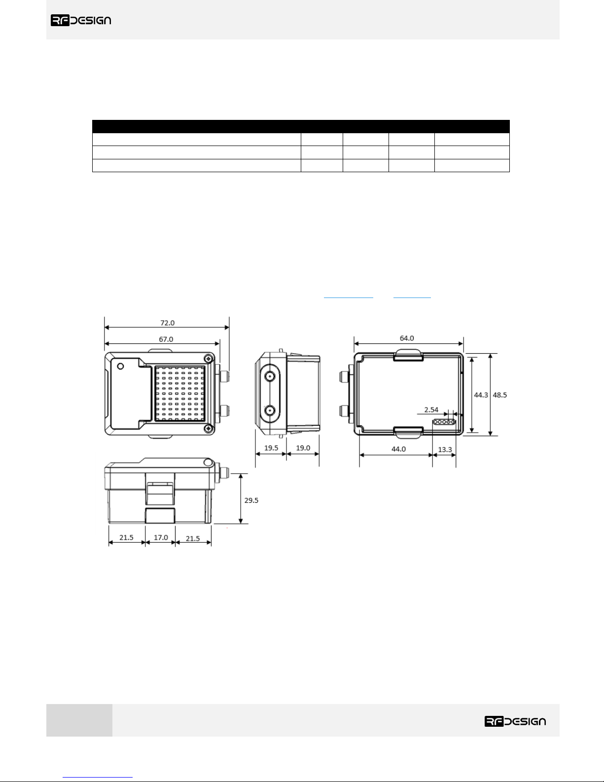
Table 9 - RC Parameters
Parameters
Min
Typical
Max
Unit
Latency
-
45
78
ms
TX Module Supply Voltage
+5 - +18
V
Current Draw (peak at input voltage of 5V)
- - 1.2
A
6.5 Physical Dimensions
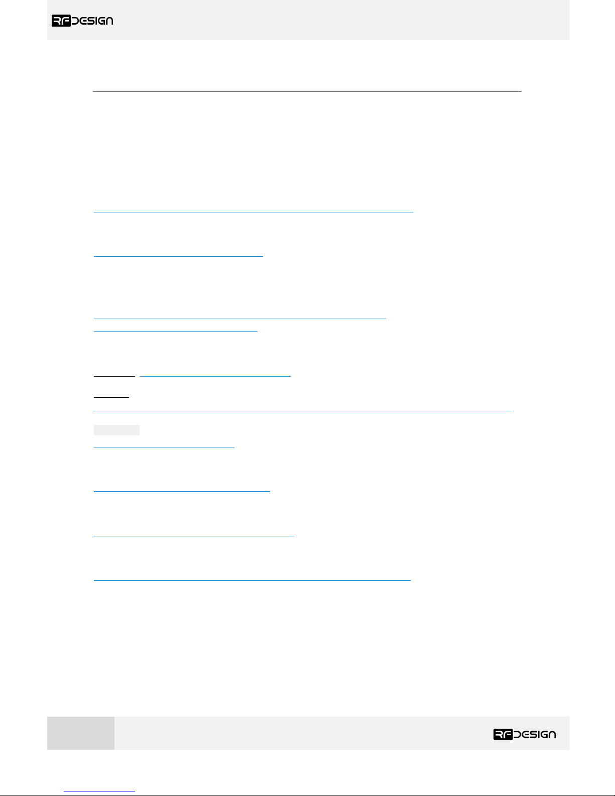
This section provides the TX Module dimensional drawings. The module it has been designed to fit
into the rear expansion bay of an FrSky Taranis X9D Plus, however users may find that it can be fitted
to other transmitters. To ensure functionality check the physical dimensions and electrical interface
are compatible and follow the information described in sections 1.2 and section 2.
Figure 22 - TX Module physical dimensions.
*Units in mm.
Page 24
RFD TX Module User Manual
www.rfdesign.com.au
23
Version 1.0 Last update 07/03/2019
7 Useful Links
TX Module WiFi firmware –
RFDesign Modem 900x Datasheet
http://files.rfdesign.com.au/Files/documents/RFD900x%20DataSheet.pdf
RFDesign Modem Firmware
http://files.rfdesign.com.au/firmware/
RFD900x Peer to Peer firmware - User Manual
http://files.rfdesign.com.au/Files/documents/RFD900x%20Peer-topeer%20User%20Manual%20V1.1.pdf
RFDesign Programming Tools
Software: http://files.rfdesign.com.au/tools/
Manual:
http://files.rfdesign.com.au/Files/documents/RFD%20Modem%20Tools%20Manual%20V1.1.pdf
CoolTerm
http://freeware.the-meiers.org/
Mission Planner
http://ardupilot.org/planner/index.html
FrSky Taranis X9D Plus
https://www.frsky-rc.com/taranis-x9d-plus-2/
Mission Planner
http://ardupilot.org/planner/docs/common-install-mission-planner.html
Page 25
RFD TX Module User Manual
www.rfdesign.com.au
24
Version 1.0 Last update 07/03/2019
8 Revision History
Version
Date
Changes
1 Alpha
07 - 03 - 2019
Prerelease document
 Loading...