

RF DataTech ART400 User Manual
ART SERIES
INSTALLATION, OPERATION
& PROGRAMMING MANUAL
COVERS
ART400, (ART400T), (ART400R)
SYNTHESISED
RADIO MODEMS & REPEATERS
October 2001 ISSUE 1. rev1.2

CONTENTS
1.0 INTRODUCTION
1.1 Products Covered
1.2 Introduction
1.3 Overview
1.3.1 Radio Frequency (RF) Section
1.3.2 Transmitter
1.3.3 Receiver
1.3.4 MPU Control & Interface Board
1.3.5 Software
1.3.6 Custom Software
1.3.7 Continuos Development
1.4 Channel Selection
1.5 Programmability
1.6 Low Power operation
1.7 Power Save Mode
1.7.1 Internal Power Save Mode
1.7.2 External Power Save Mode
1.7.3 Time Scheduling using the RTC
1.8 Soft Modem
1.9 RSSI Receive Signal Strength Indicator
1.10 Status LED’s
1.11 Optional Keypad & Display
1.12 R.F. Power
1.13 Local I.O.
1.14 12C Internal & External BUS
1.15 GPS
1.16 Internal/External Modem Operation
1.16.1 External
1.16.2 Tone Operated Switch (TOX)
1.16.3 Internal
1.17 Modes of Operation & Protocol Handling
1.17.1 Radio Modem Modes of Operation
1.17.1.1 Dumb Modem
1.17.1.2 Protocol Specific Modem
1.17.1.3 Routing Modem
1.17.1.4 Dial-up Modem
1.17.2 I.O. Modes of Operation
1.17.2.1 Isolated Network with Point to Point I/O Mapping
1.17.2.2 Network with Retrieved Data Access at Base Station
1.17.2.3 Externally Controlled Network
1.17.2.4 Custom Protocols
1.18 Network Management Software
1.19 Squelch Tail Elimination
1.20 Forward Error Correction
1.21 Automatic Frequency Control
1.22 TX Time-Out-Timer
1.23 Dual Control for Fully Duplicated Outstation
1.24 Programming, Service Installation & Management
Software
1.24.1 Programming Software
1.24.2 Installation Software
1.24.3 Service Software
1.24.4 Network Management Software
2
Commercial In Confidence

1.25 Compatibility with other products
2.0 SPECIFICATIONS
2.1 Technical Specification:
2.1.1 General
2.1.2 Transmitter
2.1.3 Receiver
2.1.4 Internal Modem
2.1.5 Bit Error Rates
2.2 Approvals and Licensing
2.2.1 UK Approvals
2.2.2 European Approvals
2.2.3 Other Approvals
2.3 Operating Channels
2.3.1 UK Telemetry Channels
2.3.2 MPT1411 Channels
2.3.3 MPT1329 Channels
2.4 Options & Accessories
2.4.1 DIN Power Supplies with Chargers
2.4.2 DIN Mounting RF Power Amplifiers
2.4.3 DIN I/O Modules
2.4.4 Leads & Cables
2.4.5 RF Adapters & Parts
2.4.6 Enclosures
2.4.7 Manuals
2.4.8 Backup Batteries
2.4.9 Antennas
3.0 OPERATION AND INTERFACE
3.1 Exploded View
3.2 Operation & Interface Description
3.1.1 Simplex, Semi-duplex & Full Duplex
3.3.2 Single or Dual Antenna Operation
3.3.3 Coax Configurations
3.3 Repeater/Store & Forward
3.3.1 Repeater
3.3.2 Store & Forward
3.3.2.1 Single Unit Operation
3.3.2.2 Two Unit Operation
3.4 Memory Expansion & Programming Port
3.5 View Showing Memory Expansion Board
3.6 Memory Expansion Board
3.6.1 Firmware Download Tool
3.6.2 Additional Memory
3.6.3 Remote Firmware Download Module
3.7 Serial and RS232 Interface
3.8 Serial Port Pin Connections
3.9 Antenna Connections
3.10 12VDC Power
3.11 I2C BUS Interface
3.12 Audio & Line Interface
3.13 Switches
3.14 Control Interface
3.15 External Audio Path
3.16 Internal Modem
3.16.1 Transmission using RTS/CTS Handshaking
3
Commercial In Confidence

3.16.2 Transmission without Hardware Handshaking
3.16.3 Data Reception
3.16.4 Transmit & Receive Timing
3.16.4.1 Receiver to transmitter Switching Times
3.16.4.2 Message Duration
3.16.4.3 Transmit to Receive Switching Times
3.16.5 Radio Data Format
3.16.6 Synchronous/Asynchromus Format
3.16.7 Transmit/Receive Timing
3.17 Error Reports
3.18 Time Out Timer
3.19 Power Save Mode
3.20 RSSI Output
3.21 Temperature Measurement
3.22 Input Voltage Measurement
3.23 Real Time Clock.
3.24 External I.O.
4.0 INSTALLATION
4.1 Introduction
4.2 Power Supplies
4.3 Effective Radiated Power (ERP)
4.4 Safe Distance Calculation
4.5 Antennas, Coax Feeders & Peripherals
4.5.1 Antennas
4.5.2 Types of Antennas
4.5.3 Omni-Directional Antennas
4.5.4 Directional Antennas
4.5.5 Patch Antennas
4.5.6 Antenna Mounting
4.5.7 Polarisation
4.5.8 Alignment
4.5.9 Antenna Coax Feeder
4.5.10 Cable length Verses Signal Loss at 500MHz
4.5.11 Coax Connectors
4.5.12 VSWR Measurement
4.5.13 Lightning Arresters
4.6 Mounting
4.6.1 ART Dimensions
4.6.2 ART Mounting
4.6.3 Antenna Connection an enclosure
4.6.4 Wall Mounting Enclosure
5.0 PROTOCOLS & APPLICATIONS
5.1 Store & Forward Using Clients Protocol
5.2 Network Routing Mode
5.2.1 AT Command Set
5.2.2 Power Saving
5.2.3 Call Set Up Procedure
5.2.4 Radio Routing
5.2.5 Wake Up Procedure
5.2.6 Implementing Registers
6.0 PROGRAMMING
4
Commercial In Confidence

6.1 Introduction
6.2 Medium
6.3 Configuration of the A4P Program
6.4 Starting the Program
6.5 Connecting the ART for local PC Programming
6.6 Programming/Reading Radio
6.7 Opening Menu
6.7.1 Directory Display
6.7.2 Version Number & Compatibility Message
6.7.3 Edit Notes
6.8 Description of Main Edit Functions
6.8.1 Main Menu
6.8.2 Radio Mode
6.8.3 Frequency Range
6.8.4 Alignment Range
6.8.5 Channel Selection Mode
6.8.5.1 Number of Channels
6.8.5.2 Channel Increments
6.8.5.3 RXD Start Frequency
6.8.5.4 TX Start Frequency
6.8.6 Power Range
6.8.7 TX Power
6.8.8 Power Save Options
6.8.8.1 Save On Time
6.8.8.2 Save Off Time
6.8.8.3 Save Resume Time
6.8.9 Serial Number
6.8.10 Note Pad
6.8.11 Lockout Time Mode
6.8.12 Lockout Time
6.8.13 Audio Response
6.8.14 Carrier Mute
6.8.15 Menu Options
6.8.15.1 Return to Main Menu
6.8.15.2 Edit Channel Data
6.8.15.2 Edit Modem setup
6.8.15.3 Custom Menus
6.9 Modem Edit Menu
6.9.1 Radio Baud Rate
6.9.2 Radio Data Bits
6.9.3 Radio Parity
6.9.4 Radio Stop Bits
6.9.5 FFSK Tone Set
6.9.6 FFSK/SYNC/ASYNC
6.9.7 Serial Baud Rate
6.9.8 Serial Data Bits
6.9.9 Serial Parity
6.9.10 Serial Stop Bits
6.9.11 RTS/CTS Hanshake
6.9.12 DCD Operation
6.9.13 DTR Shutdown
6.9.14 Lead In Delay
6.9.15 Lead Out Delay
6.9.16 Embedded Control
6.9.16.1 Network I.D
6.9.16.2 Network Address
6.10 Edit Channel Data
6.10.1 Channel Data Screen
6.10.2 Description of Channel Data Menu Options
6.10.3 RX & TX Frequency
6.10.4 Next/Previous Channel
5
Commercial In Confidence

6.10.5 Editing Channel
6.11 Calibrate Menu (Factory & Service Centre Options)
6.11.1 Test Max Power/Mod Balance
6.11.2 Set TX Frequency
6.11.3 Set RX Frequency
6.11.4 Calibrate Power
6.11.5 Set Peak Deviation
6.11.6 Internal Mod Level
6.11.7 Set Line Level
6.11.8 Cal RSSI
6.11.9 RSSI Test
6.11.10 Temperature Test
6.11.11 Input Voltage Test
6.11.12 Return to Main Menu
SOFTWARE & ANCILLARYITEMS
7.1 PC Software
7.2 Client Programming Software
7.3 Factory Programming Software
7.4 Bit Error Rate (BER) Software
7.5 Test & Alignment Software
7.6 Network Management Software
7.6.1 Installation
7.6.2 Operation within a network
7.6.3 Additional Features
7.6.4 Internal Temperature measurement
7.6.5 Input Power Supply Voltage
7.6.6 RX & TX Offset Frequency Measurement
7.6.7 & TCXO re-alignment
7.6.8 Local/Remote firmware upgrades
7.7 Future Software Developments
7.7.1 Non Intrusive Network management software
7.8 Ancillary Products
7.8.1 Power Supplies with Chargers
7.8.2 RF Power Amplifiers
7.8.3 DIN I.O. Modules
7.8.4 Enclosures
7.8.5 Leads & Cables
7.9 Adapters & Parts
7.10 Manuals
7.11 Backup Batteries
7.12 Antennas
6
Commercial In Confidence

FCC Compliance Statement
This device complies with part 15 of the FCC Rules. Operation is subject to the following two
conditions: (1) This device may not cause harmful interference, and (2) this device must
accept any interference received, including interference that may cause undesired operation.
WARNING
Changes or modifications not expressly approved by the party responsible for compliance
could void the user’s authority to operate the equipment.
NOTE:
A digital device, pursuant to part 15 of the FCC Rules. These limits are designed to provide
reasonable protection against harmful interference when the equipment is operated in a
commercial environment. This equipment generates, uses, and can radiate radio frequency
energy and, if not installed and used in accordance with the instruction manual, may cause
harmful interference to radio communications. Operation of this equipment in a residential
area is likely to cause harmful interference in which case the user will be required to correct
the interference at his own expense.
This equipment has been tested and found to comply with the limits for a Class
Industry Canada Certification
This device complies with Industry Canada RSS 119, under certification number TBD.
IC Class A Compliance
This device complies with the Class A limits for radio noise emissions as set out in the interferencecausing equipment standard entitled “Digital Apparatus,” ICES-003 of Industry Canada.
WARNING
To satisfy FCC/IC RF exposure requirements for mobile transmitting devices, a separation
distance must be maintained between the antenna of this device and persons during
operation. To ensure compliance, operations at closer than this distance in not
recommended. The following table show this distance for different gain of antennas:
Gain of Antenna
Minimum Separation Distance
(dB)
Unity 0.5
3 0.7
6 1.0
8 1.3
10 1.6
12 2.0
(metre)
7
Commercial In Confidence

INTRODUCTION
1.1 PRODUCTS COVERED
This Manual covers the R.F. Technologies ART Series Radio Modems and repeaters.
Information is provided to program, install, and operate the products in various
configurations.
With the built-in test software, first line “Go-No Go” testing can be easily performed.
Component level servicing is not covered in this document, if the product fails its first line
testing it should be returned to a service centre.
1.2 INTRODUCTION
The ART Series are high performance, very low current consumption, dual Synthesised
Radio Modems, designed specifically for the Telemetry and Data market, where the fast
transfer of data is required over reliable wireless links.
The ART was designed as a result of research into market requirements for a product that
would work in a large majority of applications. As a result the ART will fit into almost any
system using licensed, or license exempt telemetry channels in the VHF, UHF & 900MHz
bands.
The ART product is unique in its use of a single flash microprocessor to control both the RX
& TX radio modules, external interfaces, and function as a full duplex modem with
programmable speeds up to 9600bps.
1.3 OVERVIEW
1.3.1 RADIO FREQUENCY (RF) SECTION
The ART employs separate receiver and transmitter modules connected to a common
microprocessor and interface board. The RF modules have separate synthesisers to enable
full duplex operation and in simplex operation facilitates
The ART has been specially designed with very low group delay filters to provide the best
path for high speed data signals. Each RF module is a self contained unit, that plugs into the
control board and in the unlikely event that a R.F unit fails, it can be easily replaced and sent
to our service centre for repair.
No attempt should be made to repair the unit except by experienced RF personnel with
Proper RF test equipment is available.
NOTE:
performance or put its operation outside the approved specification.
1.3.2 TRANSMITTER
The transmitter can be programmed anywhere within a pre-aligned bandwidth, which is
within a wider tuneable F band, details of the bandwidths are in the technical specifications.
Both High power (20mW – 5Watts) and low power (10mW – 1Watt) products are available.
For ease of operation, all parameters are PC programmable with channel change duplicated
on the external switches.
Adjusting any of the controls within the RF module may degrade the transceiver's
very fast turn around times.
8
Commercial In Confidence
1

1.3.3 RECEIVER
The receiver is a very low current double conversion superheterodyne with an active
balanced mixer for very good intermodulation. Careful attention to spurious response,
adjacent channel and blocking performance, makes the product ideal for crowded telemetry
channels.
1.3.4 MPU CONTROL & INTERFACE BOARD
The Microprocessor (MPU) control & interface board is the heart of the product and at the
centre is a 128K flash microprocessor that controls all the interface circuits to the radio
modules and external Input/outputs. As well as the control functions, the processor provides
DSP functionality that enables full duplex modem operation between 150 – 9600bps.
The board also contains all necessary electronic potentiometers for full remote alignment and
control, these settings and other parameters are stored within the MPU ‘s non-volatile
EEPROM.
1.3.5 SOFTWARE
The processor has 128K of flash memory from which the code is executed and EEPROM for
storing programmed parameters. This ensures plenty of room for future upgrades and
custom applications.
1.3.6 CUSTOM SOFTWARE
Custom software or protocols for specific client applications, can be written and included
as PC programmable options in relatively short time scales and normally at nominal costs.
Further details can be obtained from the sales office.
1.3.7 CONTINUOUS DEVELOPMENT
The ART series has been designed with continuous development in mind and with less than
one third of the code space currently in use, there is plenty of room for protocols such as
MODBUS & TCPIP. For additional space (should it be required) a piggy back memory board
with a further 512k is available to download new code to the processor.
The fact that the product may have been deployed in the field, before changes have been
made, makes no difference, as changes and upgrades can easily be sent over the radio link
via our secure over air programming protocol.
1.4 CHANNEL SELECTION
The ART Series can be PC programmed with up to 80 discrete channels. Alternatively,
complete band allocations like the UK MPT1329 and MPT1411 bands can be downloaded
from the PC software, provided of course that the channels are within the products tuneable
bandwidth. Once programmed, channels can then be selected via rotary switches on the
front panel (or via the keypad on the display version) , from a PC program, via the serial port
or over the radio link.
1.5 PROGRAMMABILITY
Apart from one or two link selectable options (like single/dual antennas) , all the parameters
of the ART Series can be programmed via the serial port using either DOS or Windows
95/98 based software or over the radio link via the ART’s secure “over air programming
mode”. The individual program can be stored on disc for future use or printed.
9
Commercial In Confidence

1.6 LOW POWER OPERATION
The ART’s processor controls all the circuitry and power saves as a matter of course.
With no large DSP chips taking heavy current loads, the ART has probably the lowest current
consumption of any comparable radio modem on the market.
Although the 5watt product has very low current consumption, for extremely low current
applications the 1Watt version is recommended.
1.7 POWER SAVE MODE
The ART Series has both internal and external power save modes.
1.7.1 Internal Power Save Mode
The microprocessor controls the on/off function of the receiver and after a pre-programmed
time the MPU will switch on the receiver to look for a carrier. If a carrier is not detected, the
transceiver goes back into sleep mode. If during the time the transceiver is awake a carrier is
received, the unit will stay awake. After the carrier drops out, the receiver will stay awake
until the programmed resume time elapses. Once the resume time has elapsed the
transceiver will go back into sleep mode. The save ON/OFF and resume time are all
programmable via the PC program.
1.7.2 External Power Save Mode
In the external mode the ON/OFF function of the modem is controlled by the host via the
DTR line.
1.7.3 Time Scheduling using the RTC
The ART contains an embedded Real Time Clock that can be used to wake the radio modem
to process information, report back or be ready for a poll. The RTC can be synchronised
during the wake-up communication for accurate time slotting. Note this mode is not
currently in use but will be implemented in the on going software development.
1.8 SOFT MODEM
The ART features a full duplex “soft modem” which offers unparalleled performance and
flexibility over a wide range of speeds and formats and enables future formats to be
downloaded from a PC or over the air. Within a 12.5KHz channel, the unit can be
programmed for 150-2400bps FSK/FFSK with Bell202 & V23 supported, 4800bps GMSK &
9600bps 4 Level FSK.
1.9 “RSSI” RECEIVE SIGNAL STRENGTH INDICATION
Each ART has an internal individually calibrated RSSI signal which is accurately measured
by an internal A-D converter. The signal strength can then be read in dB micro volts on a PC
connected to the serial port or remotely over the air. In the case of the LCD version the level
can be directly read from the display. Alternatively the raw 0-5VDC relative to the RSSI is
available on one of the connectors.
10
Commercial In Confidence

1.10 STATUS LED’s:
The ART has 11 LED’s to enable the operator to see at a glance the status of the product and
the serial port in operation or on test.
1.11 OPTIONAL KEYPAD & DISPLAY
Provision has also been made in the design to accommodate the development of a keypad
and liquid crystal display (LCD) for local programming without the use of a PC and for
displaying the status of the product and connected I.O. modules.
1.12 RF POWER:
The ART’S are available in two power ranges: 10mW to 1 Watt for ultra low power
requirement, and 20mW to 5 Watts. The calibrated RF power level is PC and over air
programmable directly in watts & milli-watts with an accuracy of +/-1dB.
For high power (5-25Watt) applications a DIN power amplifier is available.
1.13 LOCAL DIGITAL I.O.
The ART Series has two local inputs and two outputs that can be configured and used under
the management and diagnostics software. For additional analogue or digital I.O the
ART700 Series of I.O. modules can easily be connected to the I2C bus interface.
1.14 I2C INTERNAL & EXTERNAL BUS
The ART Series features an I2C Bus which is used to communicate with other modules over
short or medium distances. The main feature of the bus is its address mode, which will only
wake up modules that are being addressed, thereby ensuring low power operation.
At the time of writing this manual a full range of analogue and digital I.O. modules are under
development, a list of them are in the specification section, with further details are available
from the sales office.
1.15 GPS
The ART Series can have a GPS module connected via the I2C bus, this enables time & date
stamping and asset tracking or more importantly, the location of nodes in large systems
where the downloading of network changes to specific nodes may be required.
1.16 INTERNAL/EXTERNAL MODEM OPERATION:
Both internal and external modems are supported, the external interface provides both flat
and de/pre-emphasised response for compatibility with older systems.
1.16.1 External
In external mode the 600 ohm input and output will accommodate a programmable range of
+3dBm to –20dBm. The output can be muted in the absence of a carrier.
1.16.2 Tone Operated Switch (TOX)
When using an external modem via the 600 ohm port, the soft decoder within the ART400
can be programmed to detect incoming FFSK or PSK signals. Once detected the transmitter
will key up and pass the incoming data.
1.16.3 Internal
The internal modem is PC programmable and is compatible with the many products in
operation around the world. In the internal mode, data is presented to the modem via the
RS232/TTL port at speeds up to 38400 and transmitted at the programmed baud rate.
Buffering is provided when the data rate is higher than the transmission rate.
11
Commercial In Confidence

1.17 MODES OF OPERATION & PROTOCOL HANDLING:
1.17.1 Radio Modem Modes of Operation
The basic modes of operation of the radio modem are as follows:
1.17.1.1 Dumb modem
The radio has no knowledge of the data it is transmitting, data is simply transmitted and
received under hardware control with the option of RTS control or initiation of transmit after
receipt of serial data, with CTS providing an optional flow control.
This configuration is useful when expanding older systems where the radios must be
compatible with others of a different manufacture.
1.17.1.2 Protocol specific modem
The radio recognises a complete frame and only transmits and receives data conforming to
that format. No addressing of radios or routing of data is performed. Protocols such as
MODBUS & DNP3 can be supported in this way.
1.17.1.3 Routing modem
The radios recognise a protocol specific frame and the address to which the frame is to be
sent. Routing information must be stored in each radio for each destination address that
requires the use of repeaters. Any radio in the system can operate as a repeater. The radio
does not perform any acknowledgement or retries. Any protocol using a fixed address field
such as MODBUS can be supported.
1.17.1.4 Dial up modem
Hayes protocol is used to dial up the radio link which may include repeaters or store &
forward stations, the route information is not stored but is passed in the dial up command in
the form of a telephone number, once the link is established it is transparent and so
independent of the protocol being transported. This allows point to point protocols such as
SLIP and PPP (and hence TCP/IP) to be conveyed. Dial up is less efficient for small data
transactions because of the data exchanges carried out during the connect and disconnect
phases.
1.17.2 I.O. Modes of Operation
1.17.2.1 Isolated network with point to point I/O mapping
Inputs and outputs at outstations are mapped to corresponding outputs and inputs at the
master.
1.17.2.2 Network with retrieved data access at base station.
Instead of mapping data to physical inputs and outputs at the master, data is exchanged in
memory. The memory is accessible using MODBUS. The base station carries out its data
retrieval process independently of the MODBUS accesses.
1.17.2.3 Externally controlled network
In this mode the base station only carries out data retrieval when requested to do so by the
MODBUS interface.
The above modes are not independent processes but are run according to set up, it is possible
to configure operation to be a mix of all three. E.g. some physical I/O might be desirable at
the base station whilst the rest is passed by MODBUS, the base station can be set to keep
polling independently in order to maintain the physical I/O but can also mix in commands
passed by MODBUS.
12
Commercial In Confidence

1.17.2.4 Custom Protocols
Custom protocols can be written and downloaded via a PC or over the air as systems require
change, thereby minimising disruption.
Should a special protocol or interface be required please contact the sales office.
1.18 NETWORK MANAGEMENT SOFTWARE
Network management software provides the user with direct access to the radio modems, for
diagnostics, programming & re-programming, safe downloading of new firmware and the
retrieval of data. All products on the I2C bus can be accessed in the same way.
1.19 SQUELCH TAIL ELIMINATION
For old or non tolerant protocols, where the presence of a mute (Squelch) tail may cause a
problem at the end of a message, a simple packetising option can be enabled.
1.20 FORWARD ERROR CORRECTION (FEC)
Forward error correction is not implemented as standard in the modem because of the loss of
throughput in good signal situations, however FEC can be offered as a custom option if
required. Note that since the internal modem offers many data speeds data integrity can be
improved simply by running a lower speed.
1.21 AUTOMATIC FREQUENCY CONTROL
The network management software, enables the outstation’s receiver and transmitter to be
frequency locked onto the base station s frequency and automatically re-aligned, thereby
minimising the effects of long term drift (ageing).
1.22 TX TIME-OUT-TIMER:
The transmitter within the ART has a time-out-timer which allows the maximum continuous
transmission time to be set in order to prevent channel blocking due to a to fault. The timer
operates in all modes and can be programmed in one second steps between 0 and 255
seconds. If programmed and the time is exceeded, transmission will cease until the action
that normally causes transmission is removed and then re-applied.
1.23 DUAL CONTROLLER FOR A FULLY DUPLICATED
OUTSTATION:
For Base Station applications the BRT Series is available, the ART products can also work in
a fully duplicated mode for critical outstation applications with the aid of an ART790 DIN
baychanger module.
1.24 PROGRAMMING, SERVICE INSTALLATION & MANAGEMENT
SOFTWARE
Dedicated PC software packages have been written that provide unrivalled versatility
combined with ease of use.
1.24.1 Programming software:
Programming software in DOS and Windows 95/98 is available for the ART Series.
1.24.2 Installation Software:
Provides engineers with relevant software tools to align antennas, check path links in both
directions, remotely adjust the RF power at each end and log the RSSI levels.
13
Commercial In Confidence

1.24.3 Service Software
Service software is available to enable competent engineers to perform first line testing of the
product and re-alignment when used in conjunction with suitable test equipment.
1.24.4 Network Management Software
Network Management software has been designed to enable system operation and
performance to be monitored.
1.25 COMPATIBILITY WITH OTHER PRODUCTS
The ART series is backward compatible with the Communique CMD400 products,
any slight differences are outlined in Section 7.
14
Commercial In Confidence

SPECIFICATIONS
2
15
Commercial In Confidence

2.1 TECHNICAL SPECIFICATIONS:
2.1.1 GENERAL
Frequency Range:
ART400TR 406 - 512MHz
Alignment Range: 25Mhz
Programmable
Bandwidth: 12MHz
Minimum Programmable
Channel Step: 6.25KHz or 5KHz
TX/RX Channel Spacing: Any within the programmable band.
Number of Channels: 80 sequential or 32 discrete user
programmable channels, field selectable via
two BCD switches, or by remote
Channel Spacing: 12.5KHz (optional 20/25/30KHz)
Mode of Operation: Single frequency simplex
Two frequency simplex (semi-duplex),
Full duplex, as standard.
Store and Forward and Repeater modes
available to custom order.
Power Requirements: 9.6V - 15VDC (Negative Ground)
12VDC, 24VDC & 50VDC (Negative or
positive Ground) available via a DIN power
converter
Fuse: Internal 3A Fast Blow
Reverse Polarity
Protection: Series Diode
Operating Temperature: -25 Deg C to +60 Deg C.
Humidity: 0 - 95% Non-Condensing
Frequency Stability: <2.0ppm -20deg C to +60deg.C
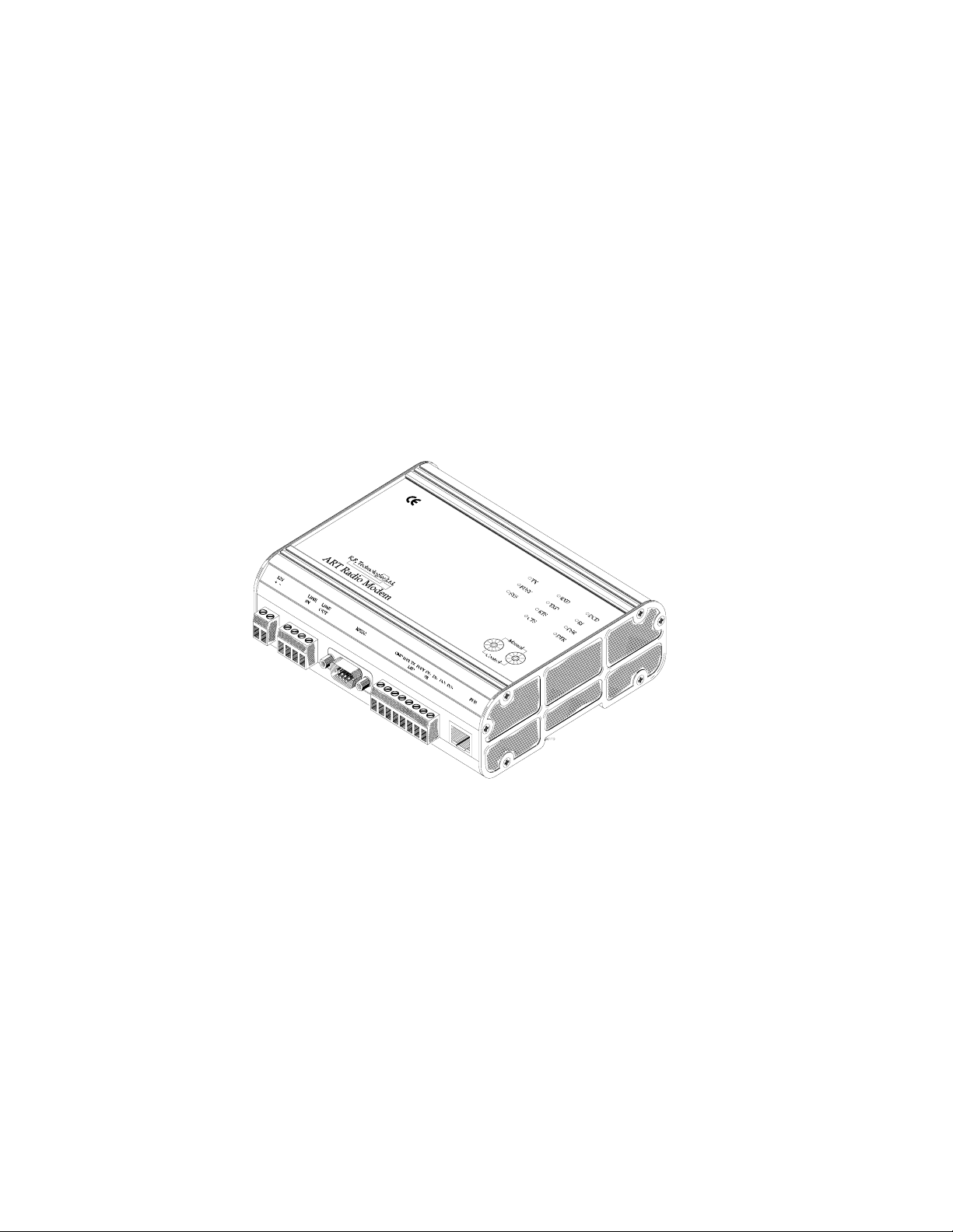
Construction: Milled Aluminium enclosure
Size: 156mm W x 125 H x 45mm D
Weight: 800gms
Connectors:
Serial Interface 9W “D” Female
Antenna BNC
Audio/Landline 4Way pluggable terminal block
16
Commercial In Confidence

DC Power 2Way pluggable terminal block
I.O. Connector 8way pluggable terminal block
LED indicators: RX RF Carrier Detect/Busy
TX Transmit
SYS System
RTS Request to Send
CTS Clear to Send
DCD Data Carrier Detect
RXD Receive Data
TXD Transmit Data
RI Ring Indication
DSR Data Set Ready
DTR Data Terminal Ready
Switches 2 x 0-9 for channel change
2.1.2 TRANSMITTER:
R.F. Output Power: ART 1Watt 10mW - 1Watt PC
programmable
ART 5Watt 50mW - 5Watts PC
programmable
Output Impedance: 50 ohms
Duty Cycle: 50% without additional heat sinking
Time Out Timer: Programmable 0 - 255 Seconds
Modulation: Internal via Modem; FFSK, GMSK & 4
level FSK.
External, +3dBm to -20dBm into 600 ohm,
Programmable Pre-emphasised or Flat
response.
TX Keying: Connection to Ground TTL compatible
The modem can be programmed to key on
detection of valid V23 or Bell 202 tones
instead of using a conventional TX enable
line.
Deviation: 7.5KHz Max. (Subject to channel spacing)
Adj. Channel Power: Better than 65dB (12..5KHz)
Hum and Noise: Better than 40dB
Spurious Emissions: < 0.25uW (4nW within specified bands)
Rise Time: < 5mS
17
Commercial In Confidence

2.1.3 RECEIVER:
Sensitivity: Better than 0.25µV (-120dBm) for 12dB
SINAD (de-emphasised response)
Spurious Response: >80dB
Blocking: >90dB relative to 1µV
Intermodulation: >70dB with 9600bps data
Adjacent Channel: >65dB at 12.5KHz
IF Frequencies: VHF & UHF 45MHz and 455KHz
900MHz 70MHz and 455KHz
Spurious Emissions: <2nW
External Audio Output: +3dBm to -20dBm into 600 ohms with
Programmable De-emphasised or Flat
response and mute enable.
Mute Response Time: <3msec
Received Signal Strength
(RSSI): Range -120dBm to -40dBm
2.1.4 INTERNAL MODEM
Serial Comms: Asynchronous or Synchronous with custom software.
Baud rate programmable between 150bps and 38400bps
Interface: Selectable RS232 or 5V TTL plus inverted/non-inverted,
Parity: Programmable odd, Even or None
Stop bits: Programmable 1 or 2
Data Bits: Programmable 7 or 8
Synchronous/Async. Programmable either up to 1200bps, above 1200bps synchronous
Signalling Formats: Programmable V23, Bell202, up to 1200 baud, 2400 baud FFSK,
4800 baud GMSK, 9600 baud 4 level FSK.
Baud date: 150 – 9600bps within 12.5KHz
Bit Error Rate: 150 - 2400 baud, less than 1 x 10⁻³ at –120dBm
4800 baud, less than 1 x 10⁻³ at –117dBm
9600 baud, less than 1 x 10⁻³ at –112dBm
2.1.5
BIT ERROR RATE BER
The Bit error rate quoted in the specification is for fixed messages with no Forward Error Correction
(FEC) and represents that which will be obtained from typical data sent over the link. The BER should
not be compared with other manufactures figures unless the data format is known, as many
18
Commercial In Confidence

manufacturers quote a BER based on an alternating data pattern, which will obviously give much
better BER results.
In the interest of improvement the above specifications are subject to change without notice.
2.2 APPROVALS AND LICENSING
The ART Series meets relevant world wide standards as outlined below, should others be
required, please contact the sales office.:
2.2.1 UK Approvals
MPT1329:
is limited to 500mW ERP.
MPT1328:
MPT1411:
BS2011:
2.2.2 European Approvals
ETS300-220
maximum RF power level of 500mW. Please note the permitted power level
may vary from country to country.
ETS300-113
ETS300-339:
2.2.3 Other Approvals
At the time of writing this document the product range is currently
undergoing approval to the following specifications.
U.S.A FCC Part 90 & 15
Canadian RSS-122/119
Australian AS 4268.2-1995
For UHF telemetry applications, under this specification the RF output power
For VHF product with the power limited to 10mW.
The unit is approved for use under MPT1411 where a licence is required and
the output power is normally stated on the licence, the maximum power
output of the ART is approximately 5Watts.
The unit complies with the Vibration specification BS2011.
The unit is approved for European licensed exempt communications with a
The unit meets the Licensed specification for data radios
The unit meets the required CE specification and carries a CE Mark.
19
Commercial In Confidence

2.3 OPERATING CHANNELS
2.3.1 UK TELEMETRY CHANNELS IN SETUP PROGRAM
From the PC Setup program the ART400 can be programmed with either all MPT1411 or
MPT1329 channels. A mixture of both channels can be entered discretely from the PC
program.
MPT1411 Channels
CHANNEL SCANNER OUTSTATIONS
1 457.50625 463.00625
2 457.51875 463.01875
3 457.53125 463.03125
4 457.54375 463.04375
5 457.55625 463.05625
6 457.56875 463.06875
7 457.58125 463.08125
8 457.59375 463.09375
9 457.60625 463.10625
10 457.61875 463.11875
11 457.63125 463.13125
12 457.64375 463.14375
13 457.65625 463.15625
14 457.66875 463.16875
15 457.68125 463.18125
16 457.69375 463.19375
17 457.70625 463.20625
18 457.71875 463.21875
19 457.73125 463.23125
20 457.74375 463.24375
21 457.75625 463.25625
22 457.76875 463.26875
23 457.78125 463.28125
24 457.79375 463.29375
25 457.80625 463.30625
26 457.81875 463.31875
27 457.83125 463.33125
28 457.84375 463.34375
29 457.85625 463.35625
30 457.86875 463.36875
31 457.88125 463.38125
32 457.89375 463.39375
33 457.90625 463.40625
34 457.91875 463.41875
35 457.93125 463.43125
36 457.94375 463.44375
37 457.95625 463.45625
38 457.96875 463.46875
39 457.98125 463.48125
40 457.99375 463.49375
41 458.00625 463.50625
20
Commercial In Confidence

42 458.01875 463.51875
43 458.03125 463.53125
44 458.04375 463.54375
45 458.05625 463.55625
46 458.06875 463.56875
47 458.08125 463.58125
48 458.09375 463.59375
49 458.10625 463.60625
50 458.11875 463.61875
51 458.13125 463.63125
52 458.14375 463.64375
53 458.15625 463.65625
54 458.16875 463.66875
55 458.18125 463.68125
56 458.19375 463.69375
57 458.20625 463.70625
58 458.21875 463.71875
59 458.23125 463.73125
60 458.24375 463.74375
61 458.25625 463.75625
62 458.26875 463.76875
63 458.28125 463.78125
64 458.29375 463.79375
65 458.30625 463.80625
66 458.31875 463.81875
67 458.33125 463.83125
68 458.34375 463.84375
69 458.35625 463.85625
70 458.36875 463.86875
71 458.38125 463.88125
72 458.39375 463.89375
73 458.40625 463.90625
74 458.41875 463.91875
75 458.43125 463.93125
76 458.44375 463.94375
77 458.45625 463.95625
78 458.46875 463.96875
79 458.48125 463.98125
80 458.49375 463.99375
21
Commercial In Confidence
 Loading...