

Page 1
Quick Start Guide
Kit Contents:
1 microLite HD Tx with transmitter mounting bracket and Litepanels kit - preassembled
1 Omni Directional Tx antenna
1Transmitter power cable set (Lemo to Tamiya)
1 Anton Bauer D-Tap power cable (D-Tap to Tamiya)
2 Audio cables (Telocate to XLR unbalanced)
1 USB-Serial adapters for configuring units (USB to RS-232)
1 USB/Power software update cable for system software updates for the MLT
1Transmitter power cable (Lemo to Tamiya/DB-9)
2 Instruction Manuals and NanoController Software on USB stick
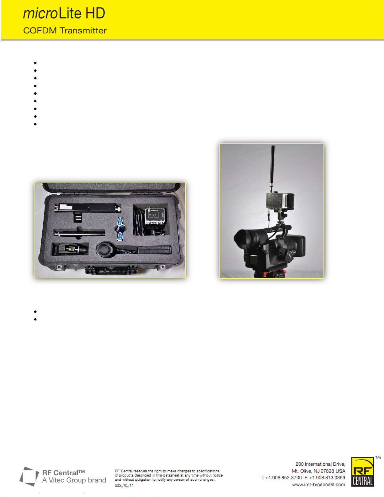
Figure 1 Figure 2
Figure 1: microLite Kit
Figure 2: microLite Transmitter mounted on camera with Litepanels mount, antenna, power cable and video cable connected.
Page 2
Quick Start Guide
microLite Quick Start Guide
1. Overview - This document contains setup instructions and use of the RF Central MicroLite System. Refer to the user manual for
more detailed technical information.
2. Transmitter set-up
2.1. Remove microLite Transmitter (MLT) from the case. Mounting bracket and Litepanels kit is preassembled. Attach
assembly to camera.
2.2. Connect video source to the Video/SDI Input (BNC jack) using a 75Ω cable.
2.3. Connect analog audio source (Telocate to XLR) to the transmitter using the 2 provided audio cables (if not using embedded
audio).
2.4. Connect TX antenna (small omni directional) to the RF output (SMA).
2.5. Connect the power source to the MLT using the supplied transmitter power cable.
2.6. Select the desired preset using the set button.
2.7. Transmit signal using the MLT Tx/Standby button.
2.8. Hi/Low button will control the power output level.
2.9. microLite Transmitter will have one of the following button controls:
2.9.1.1. BARS – Will turn internal Bars on and off.
2.9.1.2. FAN – Will turn the internal fan on and off
3. Receiver set-up
3.1. Remove microLite Receiver (MLR) from the case. The mounting bracket with MLR is preassembled.
3.2. Attach MLR to the Magic Arm using tripod mount bracket.
3.3. Connect SDI output as needed (BNC connector).
3.4. Connect audio output as needed (RCA jacks).
3.5. Connect RX antennas (larger sector directional) to the RF Inputs (N-Type).
3.6. Aim directional sector antennas in the general area of MLT operation.
3.7. Connect power source to the MLR using the power cable supplied.
3.8. Select MLR preset using the set button.
Connectors
(from left to right)
Label on Unit
Description
Lemo 7 pin
Power and Control
Power in, RS-232 Control
Telocate
Audio - Left
Audio Input
Telocate
Audio - Right
Audio Input
Lemo 5 pin
EXT
ASI In and Out
BNC
Video – SDI
Video In
Connectors
Label on Unit
Description
RCA Jacks
Left – Right
Audio Outputs
BNC
Video
Composite out only (noHD)
BNC
SDI
HD/SD SDI
Power Jack
DC In 11-28VDC
Power Input
RJ 45
No Label
VIP and Remote Control
RS-232
Remote/User Data
Remote/User Data
BNC
ASI
ASI Output
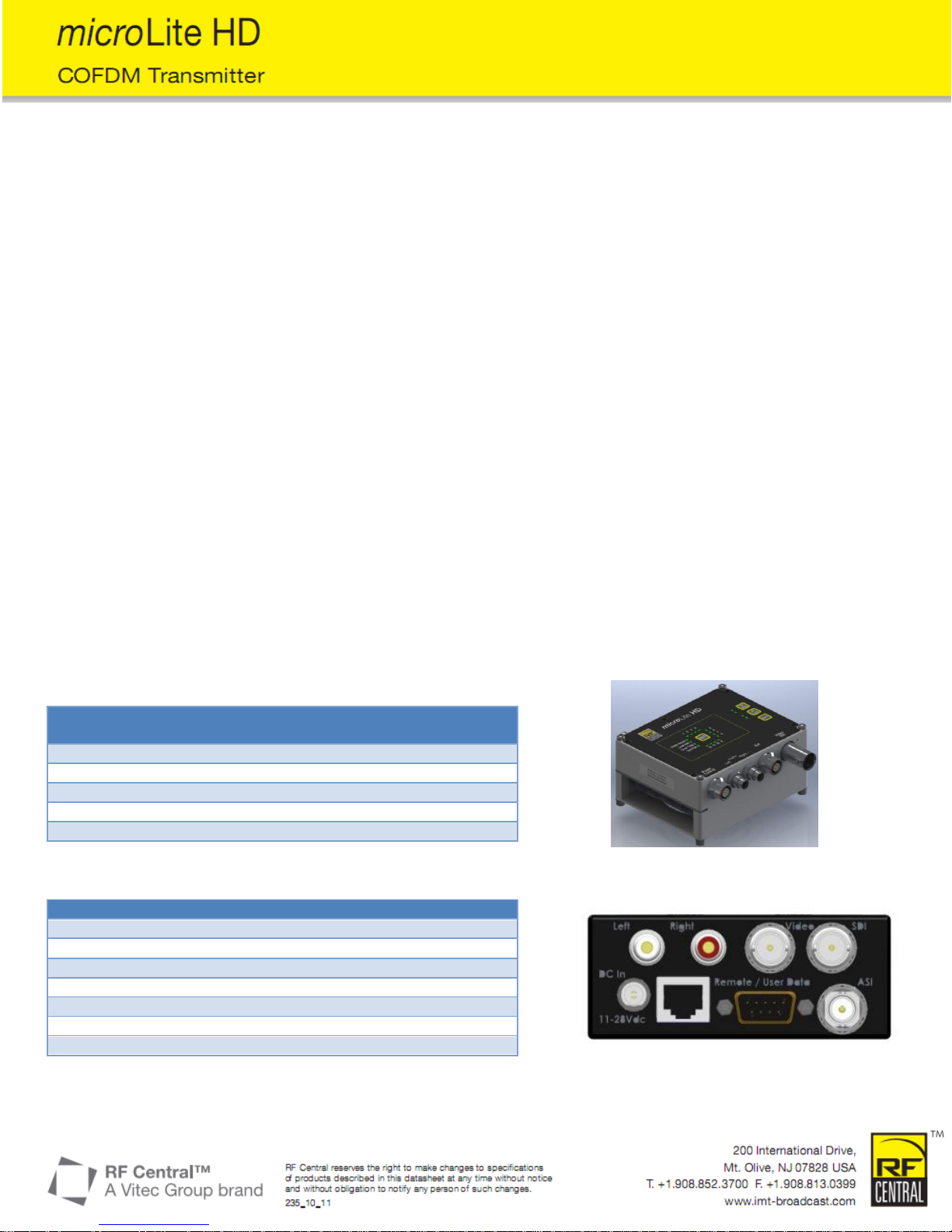
Figure 1: microLite Transmitter Connectors
Figure 2: microLite Receiver Connectors
 Loading...