


RWF111HM
RF HIGH POWER MODULE
Quick Start Guide
Revision 1.1.1 ■ 01/02/09 Confidential Page 1 of 4
RWF111HM
High Power Module
Reference Design

RWF111HM
RF HIGH POWER MODULE
Quick Start Guide
Revision 1.1.1 ■ 01/02/09 Confidential Page 2 of 4
Introduction
The RWF111HM is a 2-layer FR4 high power module to increase the power and sensitivity of any low
power module operating in 2.4GHz frequency band. It comprises of RF Front End RWF111,
UPG2214 GaAs SPDT switch, 748323024 Wurth Elektronik 2.4GHz BPF, 74LVC2G04 Dual inverter
and two 2-pin relimate male connectors for supply, ground and control.
RWF111HM RF Connections
The RWF111HM can be used as a simple add-on circuit to your existing low power module having any
transceiver operating in 2.4GHz frequency band to improve its range by increasing output power in
transmit mode and sensitivity in receive mode. The RWF111HM consist of two 50 ohm SMA
connectors to connect the RF signal from the radio to RWF111HM connector P1 (on left side) of high
power module. Connect the antenna to connector P2 (on right side) of high power module. Connectors
location can be seen in picture shown below.
To test the performance of the RWF111HM in transmit mode, connect a signal generator to P1 and a
spectrum analyzer to P2. To test the performance of RWF111HM in receive mode reverse the
connections.
The RWF111HM contains two 2 – pin relimate male connectors named as P3 and P4. This can be
used to control and power the RWF111 and UPG2214 GaAs SPDT switch respectively.
Transmit Mode
To check the module in transmit mode apply 2 volts (greater than 0.7Vcc) at P3 and 3 volts (2.9 – 4.5
volts) at P4 connector. This will turn-on on the PA of RWF111, corresponding SPDT switch arm and
enable the module in transmit mode.
Receive Mode
To check the module in receive mode apply 0.9 volts (lower than 0.3Vcc) at P3 and 3 volts (2.9 – 4.5
volts) at P4 connector. This will turn on the LNA of RWF111, corresponding SPDT switch arm and
enable the module in receive mode.
RWF111HM
RF HIGH POWER MODULE
Quick Start Guide
Revision 1.1.1 ■ 01/02/09 Confidential Page 3 of 4
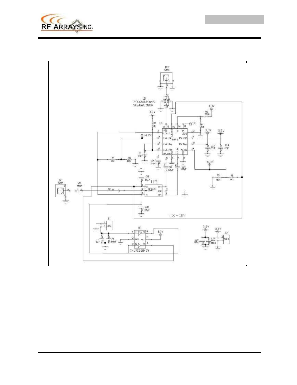
Schematic of RWF111HM

RWF111HM
RF HIGH POWER MODULE
Quick Start Guide
Revision 1.1.1 ■ 01/02/09 Confidential Page 4 of 4
http://www.rfarrays.com
Customer Service Locations
USA
RF Arrays Inc.
PO Box 14948.
Fremont California 94539, USA
Email: info@rfarrays.com,
sales@rfarrays.com
INDIA
RF Arrays Systems Pvt. Ltd.
106, Infotech Towers
South Ambazari Road
Nagpur Maharashtra
Ph: 91-712-2242459
Fax: 91-712-2249429
Email: info@rfarrays.com,
sales@rfarrays.com
Product Preview
The document contains information from the product concept specification. RF Arrays Inc. reserves
the right to change information at any time without notification.
Preliminary Information
The document contains information from the design target specification. RF Arrays Inc. reserves the
right to change information at any time without notification.
Production testing may not include testing of all parameters.
Information furnished is believed to be accurate and reliable and is provided on an “as is” basis. RF
Arrays Inc. assumes no responsibility or liability for the direct or indirect consequences of use of such
information nor for any infringement of patents or other rights of third parties, which may result from its
use. No license or indemnity is granted by implication or otherwise under any patent or other
intellectual property rights of RF Arrays Inc. or third parties. Specifications mentioned in this
publication are subject to change without notice. This publication supersedes and replaces all
information previously supplied. RF Arrays Inc. products are NOT authorized for use in implantation or
life support applications or systems without express written approval from RF Arrays Inc.
Copyright 2007 RF Arrays, Inc.
All Rights Reserved
 Loading...