

Reznor RHC DJL 4050-06, RHC DJL 4024-05, RHC DJL 4060-07, RHC DJL 4075-09, RHC DJL 4100-12 Installation, Commissioning, Servicing
...Page 1
®
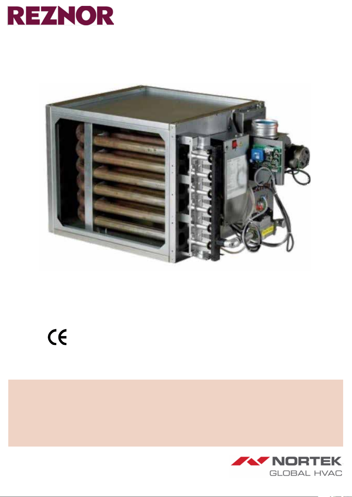
GAS-FIRED POWER VENTED UNIT HEATER
RHC DJL 4000
INSTALLATION/ COMMISSIONING/SERVICING
EU)2016/426(GAR),2009/125/EC(ErP), 2014/35/EU(LVD),and2014/30/EU(EMC)
Regulations and Directives.
The following harmonised standards have been applied:
EN 1020, EN 60335-1, EN 60335-2-102, EN 55014-1, and EN 55014-2
Please read this document carefully before commencing installation, commissioning and/or servicing.
Leave it with the end user/site agent to be placed in their premises technical file after installation.
WARNING
Improper installation, adjustment, alteration, service or maintenance can cause property damage, injury or death.
The manufacturer does not take any responsibility in the event of non-observance of the regulations concerning the connection of the apparatus causing a dan-
gerous operation possibly resulting in damage to the apparatus and/or environment in which the unit is installed.
All work must be carried out by appropriately qualified persons.
Manual Part No. D301155 Issue C
Page 2

Nortek Global HVAC (UK) Ltd.,
Fens Pool Avenue,
Brierley Hill,
West Midlands,
DY5 1QA,
United Kingdom
Herewith declares that:
EC Declaration of Incorporation
(Directive 2006/42/EC (annex ll, Sub B)
PROHIBITION TO PUT INTO SERVICE
Power-vented gas-red air heaters, type:
- RHC 4000 DJL series
Are destined to be incorporated in other machines (air-handlers) or to be combined with other machines (air-handling
systems), and are for this reason not entirely in compliance with the machinery directive 2006/42/EC. Proper integration into
the air-handling systems is required to comply with the prescribed machinery directive.
Is in conformity with the provisions of the (EU) 2016/426 (GAR), 2009/125/EC (ErP), 2014/35/EU (LVD), and 2014/30/EU
(EMC) Regulations and Directives
The following harmonised standards have been applied:
EN 1020, EN 60335-1, EN 60335-2-102, EN 55014-1, and EN 55014-2
2
Page 3

IMPORTANT NOTICE TO INSTALLERS
Installers should satisfy themselves
that the gas pipework installation is
carried out in accordance with all
current legislation, Codes of Practice and
recommendations.
Additionally it may be necessary to
protect the gas valves which form part
of the heater or burner assembly from
potential pipe contamination particularly,
but not exclusively, where copper gas
pipework is used.
In instances where copper pipework is to
be used for all or part of a gas pipework
installation, including short length final
connections then we advise that installers
consult with gas supplier or provider
and satisfy themselves what additional
precautions may be necessary.
Improper installation, adjustment,
alteration, service, or maintenance can
cause property damage, injury, or death.
Read the installation, operation, and
maintenance instructions thoroughly
before installing or servicing this
equipment.
Do not use this appliance if any part has
been immersed in water. Immediately call
a qualified service technician to inspect
the appliance and replace any gas control
that has been immersed in water.
Gas-fired appliances are not designed for
use in hazardous atmospheres containing
flammable vapours or combustible dust,
in atmospheres containing chlorinated
or halogenated hydrocarbons or in
applications with airborne silicone
substances.
Should overheating occur, or the gas
supply fail to shut off, shut off the manual
gas valve to the appliance before shutting
off the electrical supply.
This appliance is not intended for use
by persons (including children) with
reduced sensory or mental capabilities
or lack of experience and knowledge,
unless they have been given supervision
or instruction concerning use of the
appliance by a person responsible for their
safety. Children should be supervised
to ensure that they do not play with the
appliance. Any reference made to Laws,
Standards, Directives, Codes of Practice
or other recommendations governing
the application and installation of
heating appliances and which may be
referred to in Brochures, Specifications,
Quotations, and Installation, Operation
and Maintenance manuals is done so for
information and guidance purposes only
and should only be considered valid at
the time of the publication.
The manufacturer cannot be held
responsible from any matters arising
from the revision to or introduction of
new Laws, Standards, Directives, Codes
of Practice or other recommendations.
Failure to comply with the information given with these symbols will result in severe personal injury or death and/or property damage.
Note: Warning: For your safety, if you smell gas:
• Do not try to light any appliance
• Do not touch any electrical switch, do not
use any phone in your building
• Evacuate all personnel & contact your gas
supplier immediately
• Do not store or use petrol or other
flammable vapours and liquids in the
vicinity of the appliance.
• Improper installation, adjustment,
alteration, service or maintenance can
cause property damage, injury or death.
CAUTION
• Read the installation, operation and
maintenance instructions thoroughly
before installing or servicing this
equipment.
• In case of persisting problems, contact
your distributor
WARNING
• The electrical isolator should only be used
in an emergency and should not be used
for closing down the main burner, as it
switches off the fan prematurely and may
damage the heat exchanger, invalidating
the warranty.
• The temperature in the control section
of the unit may never be less than -10°C
otherwise damage could occur to the
sealing elements of the gas valve and to the
electronic components.
3
Page 4

CONTENTS PAGE
1. Introduction 5
1.1 Basic Information 5
1.2 Warranty 5
5.8
6. Servicing Instructions 15
6.1 Service procedure 15
2. Technical Data 6
2.1 Specifications 6
2.2 Definitions 7
3. General Requirements 9
3.1 General 9
3.2 Specific Heater Locations 9
3.3 Minimum Airflow Requirement 9
3.4 Maximum airflow condition 9
3.5 Combustion air supply & flue system 10
3.5.1 Flues for power vented installations 11
3.6 Air supply 11
3.7 Electrical supply 11
3.8 Gas supply 11
4. Installation 12
4.1 Unpacking and preparation 12
4.2 Fitting the combustion air inlet/flue system 12
4.2.1 Fitting the flue pipe 12
4.2.2 Guard installation on combustion air inlet pipe 12
4.3 Electrical connections 12
4.3.1 Room thermostat siting 12
5. Commissioning & Testing 13
5.1 Electrical check 13
5.2 Gas connection 13
5.3 Lighting the air heater 13
5.3.1 To turn the air heater “ON” 13
5.3.2 To turn the air heater "OFF" for short periods 13
5.3.3 To turn the air heater "OFF" for long periods 13
5.4 Air heater gas pipework 13
5.5 Adjustments 13
5.5.1 Modureg V7335A 2000 series modulation system 14
5.6 Air heater controls and operation 15
5.7 Handing over 15
7. Removal & Replacement Of Parts 16
7.1 Main burner removal 16
7.1.1 Instructions for burner removal (see Figure 17): 16
7.1.2 Instructions for re-assembly: 16
7.2 Burner injectors
7.3 Ignition system 19
7.4 Multi-functional gas control valve 19
7.5 Thermal overheat (limit) controls 19
7.6 Combustion air control pressure switch 19
8. Fault Finding 20
8.1 Main Fault Finding Chart - Lockout Indicator Light Is "Off", But Air
Heater Will Not Operate
9.
Ignition Controller Lockout Indicator Light Repeatedly
Comes "On" 21
9.1 Limit Control Fault Finding Chart (Limit Control Trips) 22
9.2 Fan Fault Finding Chart 22
10. Parts List 23
11. User Operating Instructions 24
12. Health & Safety Statement 25
12.1 General 25
12.2 Cautionary note 25
12.3 Declaration 25
12.4 Miscellaneous 25
12.5 Insulation and Seals 25
12.6 Thermostat. (Thermal overheat (limit) control LC3) Material:
Illuminating Kerosene.
12.7 Electrolytic Capacitor 25
13. ErP Information Requirements 26
19
20
25
4
Page 5

Contained within the text of the manual,
the words ‘
Caution
’ and ‘
Warning
’ are used to
highlight certain points.
Caution is used when failure to follow or
implement the instruction(s) can lead to
CAUTION
premature failure or damage to the heater
or its component parts.
Warning is used when failure to heed or
implement the instruction(s) can lead to
WARNING
not only component damage, but also to a
hazardous situation being created where
there is a risk of personal injury.
1. Introduction
Isolate any electrical supply to the heater
and controller before proceeding.
1.1 Basic Information
The instructions in this manual apply
to the RHC 4000(M) DJL gas-fired/
fan-assisted warm air heaters, installed
at an operational ambient temperature
between -15°C and +45°C.
The appliances must be installed in
accordance with the rules in force.
Before installation, check that the
local distribution conditions, nature
of gas and pressure and adjustment
of the appliance are compatible.
A permanent electricity supply of 230
volts, 50 Hz, single phase is required.
• Gas categories I2H, I2E, I2E(S)B, I2E(R)B,
I2Esi and I2EK.
• RHC 4000(M) DJL model suitable for
indoor air handlers only (when installed
where the height above floor level is greater
than 1,8 meters measured to the underside
of the appliance they may be used as a
garage air heater).
Model RHC 4000(M) DJL heaters are
approved for:
Type B22 / B52 – vertical vent (through the
roof) or horizontal vent (through the wall)
The total installation should be installed
in accordance with the rules in force,
relevant National Standards, local
regulations, and Codes of Practice.
When the external control calls for heat,
an electronic control begins the ignition
sequence to provide for a safe start.
Under normal conditions the fan motor
runs constantly and after a call for
heat it switches the heater on through
a room or duct stat. However, in some
applications, about 30 seconds after the
call for heat, the fan control relay will
activate the fan motor of the air handler.
The electronic control will supervise the
flame during the entire heating cycle to
ensure safe operation. When the required
room temperature is reached, the main
burner will shut down leaving the fan
running to cool down the heat exchanger
After approximately 45 seconds, the fan
delay relay will turn off the fan (if wired).
All models may only be used
when installed within a closed
compartment, e.g. an air handler.
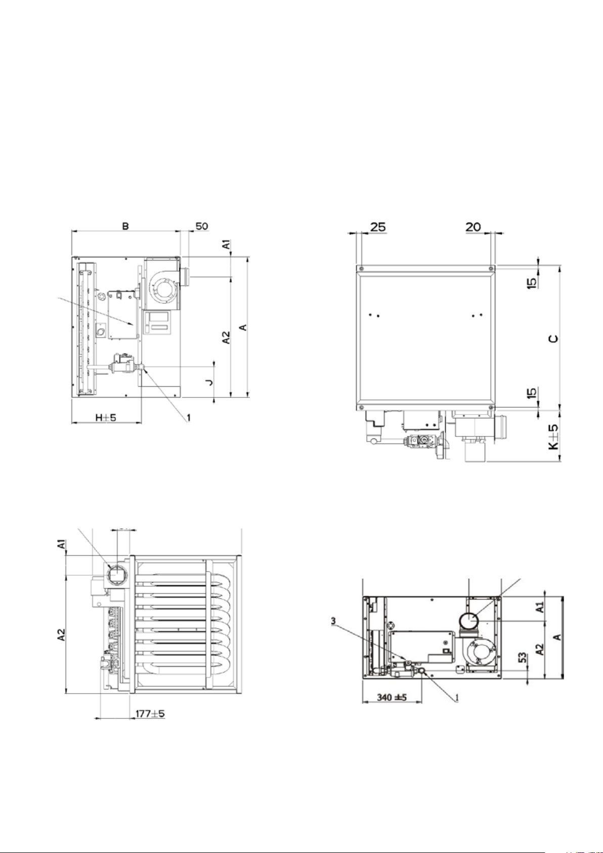
Dimensions: we refer to the
figures 1 through 9.
All dimensions are in mm
(25.4mm= 1 inch)
1.2 Warranty
Warranty is void if:
a. Model RHC 4000(M) DJL heaters are
installed in atmospheres containing
flammable vapors or atmospheres
containing chlorinated or halogenated
hydrocarbons or atmospheres containing
any silicone, aluminum oxide, etc., that
adheres to spark ignition flame sensing
probes.
b. The installation is not in accordance
with these instructions.
c. The maximum air flow through the heat
exchanger tubes is not respected (see
section 3.4).
d. The required minimum air delivery is
not respected (see table 1).
e. The duct dimensions do not comply with
the prescribed dimensions (see table 5)
f. The inlet temperature (measured at the
heat exchanger inlet) is lower than the
value stated on the chart (see table 8:
dew point occurrence chart).
All models & sizes are available for use with
natural gas with operating temperatures
between -15°C and 40°C.
These instructions are only valid for
appliances designed to operate in Europe.
If the country code and gas category on
the appliance data label does not match
the country of installation or the country
codes and gas category’s as shown
in this instruction manual, it will be
necessary to contact the distributor or
manufacturer to provide the necessary
information for the modification of
the appliance to the conditions of
use for the country of installation.
Check that the local distribution
conditions of electricity supply,
type of gas and pressure of the
5
appliance are compatible.
Page 6

2. Technical Data
2.1 Specifications
Models 4024-05 4030-06 4036-08 4050 06 4060-07 4075-09 4100-12 4125M15 4150M18
G20
Heat input Gross
G25 /
G25.3
kW High 29.3 36.6 44.0 62.0 74.6 91.5 120.0 153.5 182.9
kW Low 14.7 18.3 22.0 31.0 37.3 45.8 60.0 76.8 91.5
kW High 29.3 36.6 44.0 62.0 74.6 91.5 116.0 153.5 182.9
kW Low 14.7 18.3 22.0 31.0 37.3 45.8 60.0 76.8 91.5
G20
Heat Output (1)
G25 /
G25.3
G20 m³/h 2.8 3.5 4.2 5.9 7.1 8.7 11.5 14.6 17.5
Gas Rate High Fire
Power Consumption kW 0.153 0.153 0.153 0.153 0.153 0.153 0.153 0.282 0.282
Injector Details
Burner Pressure (2)
Minimum Air Volume with
Heat Output H1 (3)
G25 /
G25.3
G20 /
G25 /
G25.3
G20 20 mbar 9.7/2.5 9.2/2.4 7.9/2.1 7.0/1.9 7.5 / 1.9 7.5/2.1 8.3 / 2.4 7.4/2.2 7.5/2.2
G25 25 mbar 13.5/3.7 13.2/3.4 11.1/3.0 10.0/2.7 11.3 / 3.0 10.2/3.2 11.8 / 3.3 10.2/3.2 10.4/3.2
G25.3 25 mbar 13.5/3.7 13.2/3.4 11.1/3.0 10.0/2.7 11.1 / 3.0 10.2/3.2 11.7 / 3.3 10.2/3.2 10.4/3.2
V1 (4)
High Fire 24.0 29.8 36.0 50.8 61.2 75.0 100.0 126.3 151.3
Low Fire 12.0 14.9 17.9 24.0 28.6 36.0 47.0 51.0 75.8
High Fire 24.0 29.8 36.0 50.8 61.2 75.0 93.2 126.3 151.3
Low Fire 12.0 14.9 17.9 24.0 28.6 36.0 47.0 51.0 75.8
m³/h 3.3 4.1 4.9 6.9 8.3 10.2 12.9 17.1 20.3
mm 2.20 2.20 2.20 3.00 3.00 3.00 3.00 3.00 3.00
Marking 220 220 220 300 300 300 300 300 300
Quantity 5 6 8 6 7 9 12 15 18
m³/h N/A N/A N/A 3900 4700 5700 7500 N/A N/A
m³/s N/A N/A N/A 1.08 1.31 1.58 2.08 N/A N/A
kW N/A N/A N/A 50.0 60.0 73.8 97.0 N/A N/A
Minimum Air Volume with
Heat Output H2 (5)
1. Heat output depends on airflow - heat output H2 only for airflows above V2
2. With open Service door
3. H1 = heat output at airflow V1
4. V1 = minimum airflow required through enclosure
5. H2 = heat output at airflow V2
6. V2 = minimum airflow for high heat output H2
Country Code Approved Gas Category
AT, BG, CH, CY, CZ, DK, EE, ES, FI, GB, GR, HR, IE, IT, IS, LT, LV, NO, PT, RO, SE, SI, SK, TR I2H
DE, LU, PL, RO I2E
FR I2Esi
BE I2E(S)B / I2E(R)B
NL I2EK
Gas Category Gas Type
I2H / I2E Nat Gas (G20) 20 25 17.5
I2E (S) B / I2E(R)B / I2Esi Nat Gas (G20 / G25) 20 / 25 25 / 30 17.5 / 18
I2EK Nat Gas (G20 / G25.3) 20 / 25 25 / 30 17.5 / 20
V2 (6)
m³/h 2880 3290 5281 5950 7150 8800 11700 9600 12300
m³/s N/A N/A N/A 1.65 1.99 2.44 3.25 4.30 3.40
kW 24.0 29.8 35.8 50.8 61.2 75.0 100.0 126.3 151.3
Nominal Supply Pressure
(mbar)
Max Supply (mbar) Minimum Supply (mbar)
Table 1 – Technical data
Table 2.1 – Technical Data
Table 2.2 – Gas Supply Pressures
6
Page 7
2.2 Definitions
Jacket-less:
A gas-fired air heater supplied as a skeleton
appliance e.g. without case or cover.
Module:
The jacket-less gas fired air heater.
Constructor
The undertaking, which builds a module
into another casing. e.g. an air handler.
Electrical
connection
Appliance
An appliance where the air for combustion
is taken from within the area where the gas
burner is operated.
Compartment
The section of an appliance into which the
module is installed.
B22 / B52 Appliance
An appliance where the air for combustion
is taken from within the area where the gas
burner is operated.
Dew point
The condition, when the temperature is such
that the water vapour in the combustion
products condenses out.
Flue outlet
ØD
Gas
connection
Figure 1. 4024–4036 side view (mm)
Figure 3. 4024–4036 top view (mm)
Figure 4. 4050–4100 side view
Figure 2. 4024–4036 back view (mm)
7
Page 8
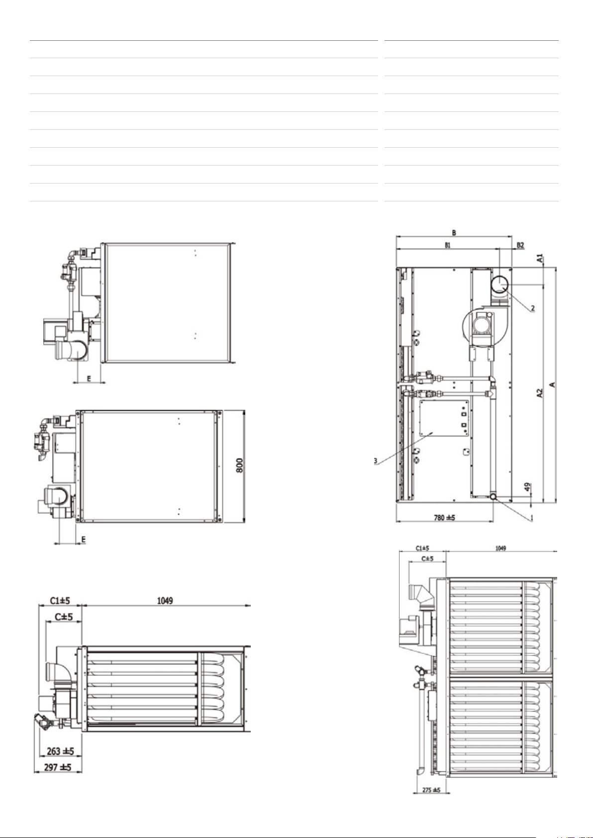
RHC models A A1 A2 B B1 B2 C C1 E H J K
4024-05 559 121 438 648 N/A N/A 677 65 N/A 425 112 225
RHC models Unit
4024-05 31 18 49
Packaging
Total
4030-06 559 121 438 648 N/A N/A 677 65 N/A 425 112 225
4036-08 837 121 716 648 N/A N/A 677 80 N/A 425 181 230
4050-06 531 85 466 800 613 187 224 268 118 N/A N/A N/A
4060-07 601 160 441 800 613 187 224 268 118 N/A N/A N/A
4075-09 741 160 581 800 613 187 224 268 118 N/A N/A N/A
4100-12 950 160 790 800 613 187 224 268 118 N/A N/A N/A
4125M15 1272 190 1082 930 778 152 361 348 118 N/A N/A N/A
4150M18 1481 190 1291 930 778 152 361 348 118 N/A N/A N/A
4030-06 33 18 51
4036-08 52 23 75
4050-06 90 29 119
4060-07 100 29 129
4075-09 120 29 149
4100-12 149 29 178
4125M15 220 58 278
4150M18 250 58 308
Table 3 – Weights (Kg)Table 2.2. - Mounting flange & dimensions
Figure 5. 4125M–4150M top view
Figure 6. 4050–4100 top view
Figure 8. 4125M–4150M side view
Figure 7. 4050–4100 front view
8
Figure 9. 4125M–4150M front view
Page 9
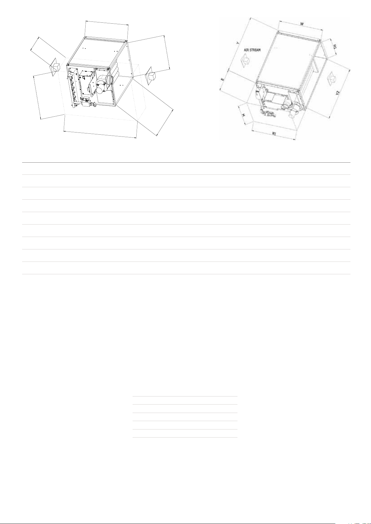
Figure 10. Compartment dimensions 4024–4036
W
H
D
C
B
A
AIR STREAM
W
H
D
C
B
A
AIR STREAM
Models A B C D minimum D maximum E H H1 W W1 Y Y2
4024-05 509 617 648 315 393 N/A 650 N/A 1100 N/A N/A N/A
4030-06 509 617 648 315 393 N/A 650 N/A 1100 N/A N/A N/A
4036-08 787 617 648 330 408 N/A 1000 N/A 1100 N/A N/A N/A
4050-06 N/A N/A N/A N/A N/A 400 531 461 800 800 1049 975
4060-07 N/A N/A N/A N/A N/A 400 601 531 800 800 1049 975
4075-09 N/A N/A N/A N/A N/A 400 741 671 800 800 1049 975
4100-12 N/A N/A N/A N/A N/A 400 950 880 800 800 1049 975
4125M15 N/A N/A N/A N/A N/A 420 1272 1202 930 930 1049 975
4150M18 N/A N/A N/A N/A N/A 420 1481 1411 930 930 1049 975
Figure 11. Compartment dimensions 4050–4150
Table 4 – Compartment dimensions (mm)
3. General Requirements
3.1 General
It is important that all gas appliances are
installed in accordance with the rules
in force and by appropriately qualified
persons. Failure to install appliances
correctly could lead to prosecution. It is
in your own interest and that of safety
to ensure compliance with the law.
Caution : Air heaters should not be installed in
corrosive atmospheres, i.e. near plating spray or
de-greasing plants or in areas where there is a
fire risk.
Care should be exercised when designing
ducting systems especially with regard
to the application of restriction and
direction turning fittings, i.e. elbows
directly on to the air heater, doing so can
cause an uneven and turbulent air flow
across the heat exchanger resulting in
heat exchanger spots and nuisance shut
down of the gas burner due to localized
overheating, thus activating thermal overheat controls.
The location must also provide sufficient
space to allow the heater to be serviced.
3.2 Specific Heater Locations
DJL installation :
Do not locate the air heater where it may be
exposed to water spry, rain, etc.
The location chosen for the air
heater must permit the provision of
a satisfactory flue system venting to
outdoor atmosphere and adequately
ventilated to provide for combustion air.
Installation clearances (mm)
(towards combustible materials)
Top 150
Flue Connector 150
Access Panel 600
Non-Access Side 150
Bottom 50
Table 5 – Installation clearances (mm)
3.3 Minimum Airflow Requirement
The minimum airflow duty through the
heating section enclosure (see figures 10 and
11) must be observed as indicated in table 1.
3.4 Maximum airflow condition
Special attention must be given to
ensure that the temperature rise of
the air, passing through the enclosure
(duct channel) around the heat
exchanger tubes, is high enough to
avoid condensation forming within the
tubes. This condensation forming could
occur by super cooling of the products
of combustion. Such condensation can
be the source of severe corrosion and
damage to tubes or part of the tubes.
The chart below indicates the probability
of condensation forming within the tubes
reference :
• The temperature rise of the air through the
enclosure (around the tubes).
• The inlet air temperature passing over the
heat exchanger
• In function of the expected minimum inlet
air temperature, the minimum required
temperature rise (to avoid condensation)
must be derived from the chart shown
below.
9
Page 10
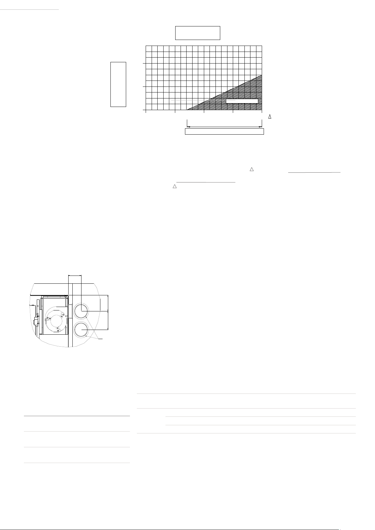
EURO-C 4000 R(JL)
EURO-C 4000 D(JL)
CONDENSATION POINT
-20 ° C
0 ° C
20 ° C
40K 20K 0K
T
T
INLET AIR TEMPERATURE
30K
CONDENSATION ZONE
AT THE HEAT EXCHANGER
10K
TEMPERATURE RISE OVER THE HEAT EXCHANGER
EURO-C 4000 R(JL)
EURO-C 4000 D(JL)
Table 6 – Dew point occurrence chart (condensation zone)
E
F
D
SEALING RING
PN: 06 22786 "Z2"
Example
• Expected minimum inlet temperature =
-5°C
• Minimum required temperature rise shown
on the chart = +13°K
Table 1 on page 6 indicates the heat
output (kW) of the different models.
3.5 Combustion air supply & flue system
All products of combustion must be flued to
outdoor atmosphere.
Figure 12. Combustion air and flue pipe sockets
The maximum allowable airflow [through
the enclosure (duct channel) around the
tubes] can be calculated as follows :
Vmax (m³/h) = heat output (kW) x 1000
Tminimum x 0.3423
For air heaters with modulating gas valve, attention
must be given to determine the maximum allowable
airflow in function of the appropriate heat input.
The air heater must be installed as a
power vented (Type B) heater, which
requires only a flue pipe exhausting
to outdoors and takescombustion air
directly from the space to be heated.
For models fitted with the optional
vestibule, an air inlet terminal must be
fitted into the air inlet socket (see figure
14).
The center distance between the combustion
air inlet socket and the flue outlet socket is
225mm for all 4050-4150M models.
Each appliance requires it’s own individual
flue system. When several appliances are
installed, one common flue and combustion
air system, thus combining several heaters,
is not allowed
Example
Tminimum = 13K (with minimum
inlet temperature = -5°C)
Model 4075 09 at 50% modulation
(see table 1 ‘output’) : 36W
results into:
Vmax (m³/h) - 36 kW x 1000 - 8090m³/h
Note:
The flue must be installed in accordance with
national and local regulations. Failure to provide proper
fluing could result in death, serious injury and/or property
damage. The air heater must be installed with a flue to
the outside of the building. Safe operation of any power
vented gas apparatus requires a properly operating flue
system, correct provision for combustion air, and regular
maintenance and inspection.
Use of flue restriction rings
(Only for 4000M units !!)
To ensure the efficiency of the
units, eventually a flue restriction
ring needs to be fitted in the outlet
collar of the venter housing. The
diameter of the restriction ring will be
determined by the flue pipe length.
Models D E F
4024 121 105 140
4030 121 105 140
4036 121 178 225
10
B Appliance
Table 7.1 – Combustion air & flue pipe sockets
Combustion out and inlet application 4125M.15 4150M.18
1 x 1M pipe length till 1 x 3M pipe length 86mm 90mm
1 x 4M pipe length till 1 x 6M pipe length 90mm 93mm
1 x 7M pipe length till 1 x 9M pipe length 93mm 95mm
Table 7.2 – Diameter flue restrictors for DJL
Page 11

3.5.1 Flues for power vented installations
(Type B appliances)
Air for combustion will be taken from
within the space where the heater is
installed. Ensure that an adequate air
supply for combustion and ventilation
is provided within the building in
accordance with the regulations &
rules in force. Table 8 shows flue pipe
sizes and maximum vent lengths. The
minimum flue length is 0.5 meters.
The combustion air inlet socket at
the appliance must be foreseen with
an inlet grill of class IP20 (for indoor
applications, or an approved vertical
flue terminal for outdoor terminations).
Indoor air inlet socket = PN 60-50712-300
(100mm), PN 60-50712-130282 (130mm)
Outdoor air inlet cap = PN 33-54-107
(100mm), PN 33-54-207 (130mm)
Outdoor air inlet 250mm extension
pipe = PN 33-54-103 (100mm),
PN 33-54-203 (130mm)
Note:
extension pipe must be used with the outdoor
inlet cap.
Models 4024–4030 4036 4050–4150
Heater socket &
pipe dia
Centre distance 165 225 225
Maximum straight
length
Equivalent length
of 45° elbow
Equivalent length
of 90° elbow
Table 8 – Combustion air inlet & flue pipe
100 130 130
7.5 7.5 9
0.75 0.75 0.75
1.5 1.5 1.5
requirements
To avoid leakage use single wall
flue pipes of seamless aluminium or
stainless steel. All joints must be sealed
to prevent products of combustion
from leaking into the building. An
approved flue terminal is required.
If the flue passes through a combustible
element of the building it must be
enclosed by a sleeve of non-combustible
material and separated from the
sleeve by at least a 25mm air break.
The temperature of any combustible
material near to the flue must not exceed
65°C when the heater is in operation.
The flue must be at least 50mm away from
any combustible material.
WARNING
Single wall flue pipe exposed to cold
air or run through unheated areas must
be insulated. Where condensation
is unavoidable, provision must be
made for the condensation to flow
freely to a point to which it can be
released, i.e. a drain or gully.
The condensation drain from the flue
must be constructed from non-corrodible
material not less than 20mm diameter.
Copper or copper-based alloys must
not be used for condensation drains.
3.6 Air supply
This model air heater is installed as a
type B application and is designed to
WARNING
take air for combustion from the space
in which it is installed. Do not restrict
the combustion air intake.
It is important to ensure that there is an
adequate air supply at all times for both
combustion and heating requirements.
Modern constructions involve the
greater use of insulation, improved
vapor barriers, and weather- proofing.
This practice means that buildings are
sealed much tighter than in the past.
The combustion air supply for a power
vented gas fired air heater (Type B
installation) can be affected by lack of air
supply. Natural infiltration may not be
adequate.
Use of extract fans aggravates this
situation. It is important to ensure that
there is an adequate air supply at all
times. Reliance on doors and windows
is not allowed. Always ensure that an
adequate inlet for fresh air for combustion
is provided sized to suit the total
installation of any combustion apparatus.
Fit an access guard (IP20) to the
combustion air inlet and take
appropriate action to ensure that it
remains unblocked. See national
installation requirements for aeration
and ventilation of buildings..
3.7 Electrical supply
Wiring external to the air heater must be
carried out in accordance with the rules
in force and by appropriately qualified
persons.
Check the electrical specification is in
accordance with the specification on the
appliance data plate. A unique appliance
wiring diagram is supplied as a separate
document attached to this one plus an
additional copy attached to the air heater.
A constant 230 volt 50 Hertz single phase
with neutral link fused electricity supply
is required. All heaters and controls
must be earthed. A lockable isolator with
contact separation of at least 3.0mm on
all poles should be installed adjacent to
the appliance and within reach of any
person working on the heater.
When a number of heaters are to be
connected as part of a single installation
each heater must be provided with a
separate isolator.
Ensure that electrical supply cables
do not touch the very hot combustion
collector box. The cables must be
fitted on the gas pipe inside the service
compartment. The final connection must
be made in the terminals provided in the
control compartment. Follow the wiring
diagram provided with the air heater and
air handler.
Electrical supply cable conductor
size should be 1.5mm. Fit the cord
grip supplied with the heater. The
length of conductors between the
cord grip and the terminals must be
such that, in the event that the cable
becomes taut the line conductors
do so before the earth conductor.
3.8 Gas supply
(gas service connection Rc ¾)
RHC 4000 DJL heaters are designed
to operate on natural gas (G20 / G25 /
G25.3). Refer to the specifications in
section 2 of this document and to the data
plate for details of supply pressures.
The gas meter and gas service must be
checked by the supply undertaking to
ensure that they are adequate to deal with
the total load of all gas fired apparatus
installed.
Connection to a gas network may only
be carried out by appropriately qualified
persons. The gas installation must
comply with the rules in force using
materials appropriate for gas installation.
To facilitate servicing, the air heater must
be fitted with an approved gas service tap
and union fitting or union tap adjacent to
the appliance.
The inlet gas supply line must be
installed so as to permit the access door
to be opened and to allow removal of
slide out burner assembly.
An adequate gas supply sized to
provide the dynamic pressure for the
volume required for the air heater(s)
is essential to maintain the nominal
heat input. Account of other gas
fired plant using the same gas service
must also be taken into account.
11
Page 12
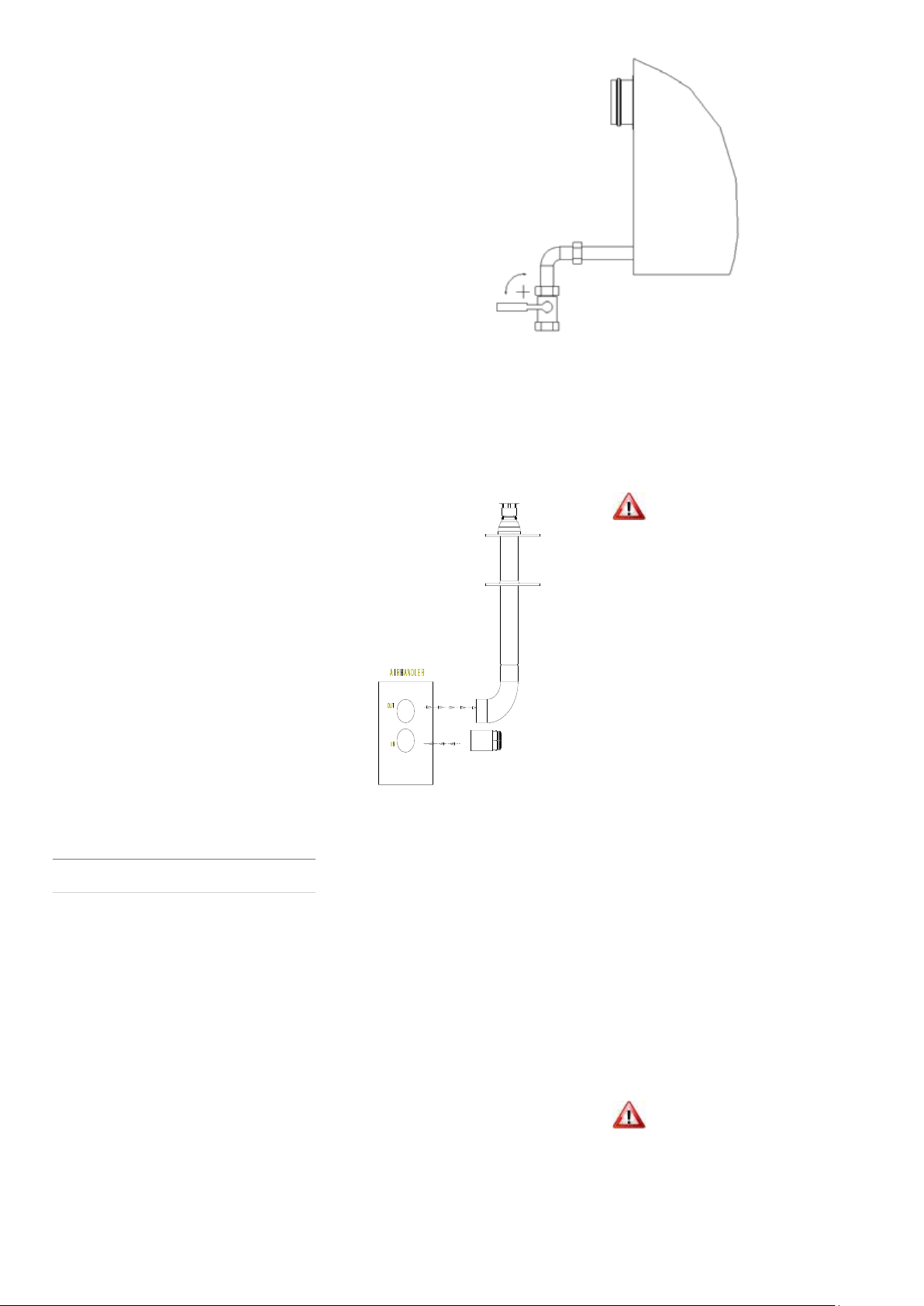
A 90° action, positive stopped gas
service tap must be fitted adjacent to the
appliance, fitted in a manner to facilitate
appliance burner removal for service
purposes, see Figure 13.
Ensure that the gas service includes a
filter and has been tested and purged in
accordance with prescribed practice prior
to commissioning and taking the appliance
into service.
As a rule, gas service pipes should not
be routed through air ducts. Should it be
necessary to do so then pipe work joints
must not be made within the air duct.
4. Installation
Figure 13. Gas connection detail ¾
4.1 Unpacking and preparation
Prior to dispatch, the air heater was operated
and tested at the factory.
Check the shipping label and data plate
to ensure the specification of gas and
electrical supplies are compatible. Read
this document and become familiar with
the installation requirements and the
appliance before commencing installation.
4.2 Fitting the combustion air inlet/
flue system
Flue pipe runs may be horizontal or vertical
and terminate either through the wall or roof.
See Table 8 on page 11 for maximum vent
length for an appliance installed as type B.
4.2.1 Fitting the flue pipe
Models 4024 - 4030 4036-4150
Flue Pipe socket size
(Ømm)
100 130
Flue pipes must be sealed. Use seamless,
aluminium or stainless steel pipe. Follow
pipe manufacturer's instructions.
Table 9 – Flue pipe socket size (Ømm)
4.2.2 Guard installation on combustion air
inlet pipe
(Type B installations) for power vent
When installed as a type B appliance, protect
the inlet by fitting an access guard on the
socket. Do not block this socket as it supplies
combustion air for the burner. The inlet must
be provided with a protection grill IP20 (see
Figure 14).
12
Figure 14.
Indoor air inlet socket = PN 60-50712-300
(100mm), PN 60-50712-130282 (130mm)
Outdoor air inlet cap = PN 33-54-107
(100mm), PN 33-54-207 (130mm)
Outdoor air inlet 250mm extension
pipe = PN 33-54-103 (100mm),
PN 33-54-203 (130mm)
Note:
extension pipe must be used with the outdoor
inlet cap.
4.3 Electrical connections
The electrical installation may only be
carried out by appropriately qualified
persons observing the rules in force. All
electrical connections should be made
in the heater control compartment.
Screw type terminals are provided.
Connections should be in accordance
with the terminal markings and the
wiring diagram affixed to the air heater
or included with this document.
This appliance must be earthed.
WARNING
The minimum external controls required
for the air heater are a room thermostat. It
is essential the main input line and neutral
to terminals L and N remains live at all
times even when the appliance is switch
off this ist to ensure correct operation of
the unit. An indicator light and burnerreset button are fitted inside the appliance.
To add a remote reset button, make
connections to the terminals in the electric
box as indicated on the wiring diagram.
Note:
If the reset button requires activating for any
reason the cause should be identified before resetting.
After resetting stay with the appliance for long enough to
ensure that lockout does not reoccur (suggest 5 minutes).
4.3.1 Room thermostat siting
The siting of the room thermostat is
important. It should not be fitted on
an outside wall. Avoid location in
draughty areas or where it may be
influenced by heat sources e.g. The sun,
process plant, etc. The thermostat or
temperature sensor should be mounted
on a vibration free surface and mounted
about 1,5 meters above floor level.
Follow the thermostat manufacturers
fitting instructions. The thermostat must
be suitable for switching 230 volts.
Do not attempt to control more than 1
air heater from a room thermostat or
WARNING
control panel unless a properly wired
relay is fitted. Follow instructions
supplied with such panels.
Page 13
5. Commissioning & Testing
Appropriately qualified persons may only
carry out the commissioning and testing.
This section should be read and fully
understood before commencing
commissioning and testing.
5.1 Electrical check
After completion of the installation and
before switching on the electrical supply
to the appliance, a qualified electrician
must carry out a preliminary check. The
following must be checked:
• Check that electrical cables/wiring do not
touch the ‘hot’ combustion collector box
and fix them all on the gas pipe.
• Check that all wiring is connected in
accordance with the appliance
circuit diagram.
• Ascertain that the correct fuse value and
cable size has been provided.
• Check to ensure that the appliance is
earthen by conducting an earth continuity
test. Connect a test meter, one lead to the
appliance earth terminal and the other
to the mains incoming earth point at the
electrical isolator. A resistance reading
of 1,0 ohm or less must be indicated. If a
higher reading is obtained, check all cable
connections to ensure adequate security
and cleanliness. If problem still exists it
may be necessary to consult the electricity
supply undertaking.
• Carry out a polarity test. Connect one lead
of a suitable AC voltmeter to earth and
connect the other lead to the live supply
terminal (L) at the air heater. Switch ON
the power to the air heater and check for
correct voltage. The same result should
be obtained by connecting the test leads
between live and neutral.
• Connect the voltmeter test leads to
N and E.
• A reading of ±0V should be obtained. If
these tests do not conform to the above,
there is a fault, which must be rectified
before proceeding further with
the commissioning.
• Check that a suitable thermostat or control
panel has been fitted.
• Ensure that an electrical isolator with twopole separation with a minimum air break
between poles of 3mm has been fitted
adjacent to the air heater.
RHC 4000 DJL air heaters are all fitted with
automatic spark ignition systems. When
adequate airflow for combustion is proven
by an air proving control and a pre-purge
period has elapsed, the integral igniter and
multi-functional gas control operate.
The ignition spark ignites the gas creating
the burner flame, which is detected by a
flame rod sensor. If a burner flame is not
detected, the ignition controller proceeds
to lockout and requires manually resetting.
Lockout is indicated by the red warning
light on the wiring panel inside the heater.
Note:
before attempting reset.
5.3.1 To turn the air heater “ON”
The following checks should be carried
out before attempting to light the air heater.
Note:
ignition controller may be in lockout position and require
resetting. This may occur especially if the appliance has
been on stand-by for a prolonged period.
5.3.2 To turn the air heater "OFF" for short
periods
Adjust the room thermostat to its lowest
setting or 'OFF'. The fan will continue to
run to cool the heater and then switch OFF
automatically (or follow the instructions of
the air handler).
If the first reset is not successful, wait 15 seconds
• Ensure all burner tubes contain a x-baffle
and are fully inserted into the tubes.
There is a tab at one end to prevent over
insertion.
• Ensure that the gas supply to the air heater
is turned ON;
• Ensure that the electrical supply to the air
heater is switched ON;
• If fitted ensure that a time switch is set to
an ON period;
• Set room thermostat to call for heat. e.g.
above room ambient temperature (see air
handling system instructions;)
•
Ensure the NOx reducing x-baffle is fitted
flush into each burner tube.
• Adjust the room thermostat to the required
operating comfort temperature. The air
heater will now start automatically when
the room thermostat calls for heat,
If the air heater will not start on initial start-up, the
installation, connections may have
been loosened. Check the soundness
of the appliance pipe work using a
soapy solution. If any leaks are found
they must be rectified immediately.
Never use a flame for testing for gas
soundness
CAUTION
5.4 Adjustments
2a/2b
3
4
1
6
8
5
7
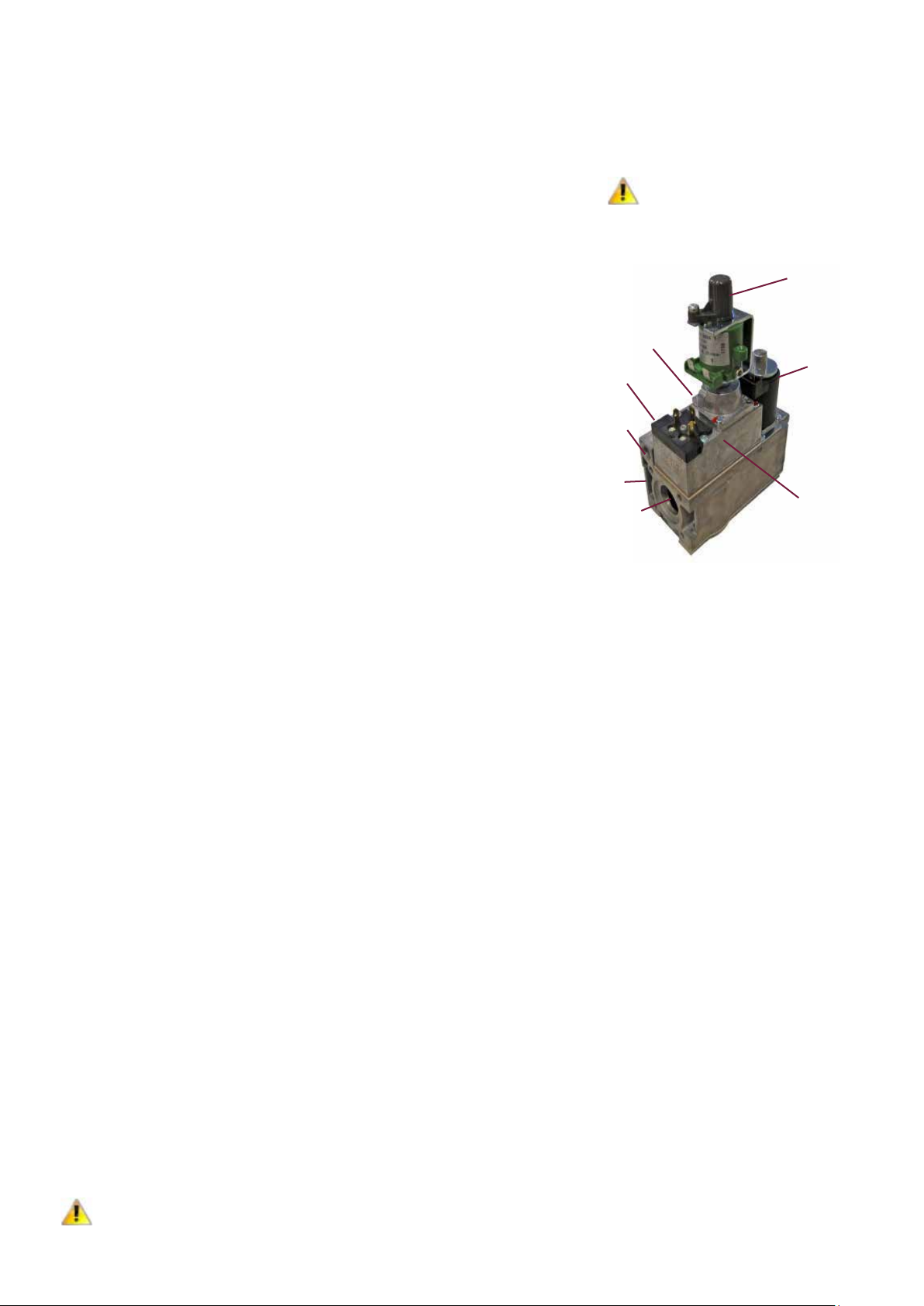
Figure 15. Honeywell gas valve
Legend
1. Shut-off solenoid valve EV1
2.
2a. Adjustment low fire
2b. Adjustment high fire
3. Inlet pressure test point (not visible on
figure 15)
4. Outlet pressure test point (not visible on
figure 15)
5. Shut-off solenoid valve EV2
6. Pilot outlet
7. Main gas outlet
8. Holes (M5) for fixing flange
5.2 Gas connection
Only persons formally qualified to
work on gas-fired apparatus may carry
out commissioning and testing. The
whole of the gas service installation
including the meter must be inspected,
tested for soundness and purged
in accordance with appropriate
requirements by a qualified person.
Never use a flame for checking gas
soundness.
CAUTION
5.3 Lighting the air heater
5.3.3 To turn the air heater "OFF" for long
periods
Adjust the room thermostat to OFF
or its lowest setting. When the fan
has stopped, turn OFF the gas supply
and then switch OFF the electricity
supply to the air heater (or follow the
instructions of the air handler).
Air heater gas pipework
The soundness of the air heater pipe
work has been checked prior to
leaving the factory. However during
13
Page 14
Burner gas pressure
The gas pressure is set for the required
heat input before the appliance leaves
the factory, normally provided the gas
supply to the air heater is in accordance
with the supply pressure described on
the appliance data plate the operating
pressure will not require adjustment.
To check the pressure, the following
procedure should be carried out:
RHC 4000 4024 05 4030 06 4036 08 4050 06 4060 07 4075 09 4100 12 4125M 15 4150M 18
• Ascertain from section 2 and the
appliance data plate the correct operating
gas pressure for the air heater;
• Turn the room thermostat control to its
lowest setting (see instructions of the air
handler);
• Remove screw from the outlet pressure
test point of the multi-functional control
valve. Connect a manometer to the test
point;
• Adjust the room thermostat to call for heat
e.g. above room ambient temperature;
• Observe the burner gas pressure on the
manometer and compare to the required
pressure (table 10);
• If necessary, adjust the burner gas
pressure. Refer to following section for
procedure;
• Set room thermostat to lowest setting to
turn OFF the burners. Replace the test
point screw (if removed) and with the
main burner alight, test for gas soundness
using a soapy solution.
• Reset temperature control/room
thermostat to comfort operating level.
Pressure
at 100%
Burner Pressure
Pressure
at 50%
Gas Consumption at 50%
G20 mbar 9.7 9.2 7.9 7.0 7.5 7.5 8.3 7.4 7.5
G25 mbar 13.5 13.2 11.1 10.0 11.3 10.2 11.8 10.2 10.4
G25.3 mbar 13.5 13.2 11.1 10.0 11.1 10.2 11.7 10.2 10.4
G20 mbar 2.5 2.4 2.1 1.9 1.9 2.1 2.4 2.2 2.2
G25 mbar 3.7 3.4 3.0 2.7 3.0 3.2 3.3 3.2 3.2
G25.3 mbar 3.7 3.4 3.0 2.7 3.0 3.2 3.3 3.2 3.2
G20 m³/h 1.4 1.7 2.1 3.0 3.6 4.4 5.7 7.3 8.7
G25/
G25.3
5.5.1 Modureg V7335A 2000 series
modulation system
The Modureg V7335A 2000 Series
Modulating gas pressure regulators
are fitted as standard and used on
"Honeywell" Multifunctional gas controls
for modulating the burner gas pressure
for firing over the range 50% to 100%
of the nominal high fire burner rate.
Heaters must be controlled so that burner
start-up takes place in the high fire (100%)
CAUTION
mode.
Modureg gas pressure regulators require
to be powered by a maximum 24V
DC voltage over the range 15–65 mA
maximum. Maximum outlet pressure
occurs at the high set point value (high
fire). Minimum outlet pressure occurs
at low set point value (low fire).
m³/h 1.6 2.0 2.4 3.4 4.1 5.1 6.7 8.5 10.2
Table 10 – gas pressures and low rate consumption
Allow time for gas pressure to stabilise before
making adjustments.
To set minimum (low fire) 50% rate (see table 10)
1. Remove regulator cover cap;
2. Disconnect electrical connection to the
regulator coil;
3. Energise operator, set control in operation
and wait until outlet pressure is recorded
on manometer;
4. Use a 9mm wrench to turn the minimum
rate adjustment screw clockwise to
increase or counter-clockwise to decrease
the minimum pressure setting
The minimum pressure setting must be
adjusted first, because any adjustment of
the minimum pressure setting influences
the maximum pressure setting.
values
1
2
3
4
5
6
The power signal may be obtained from a
system amplifier, which may be an integral
control within the appliance, or, from a
remote control system designed to provide
the required controlling voltages
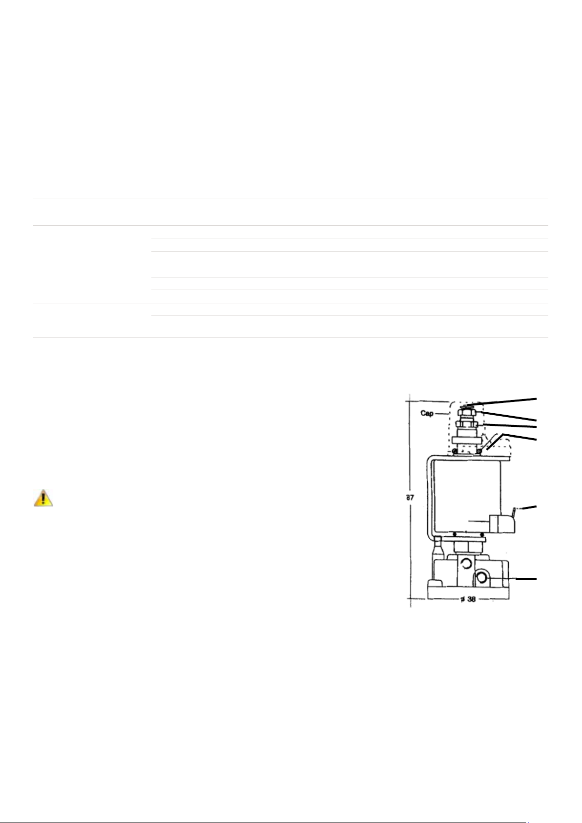
Adjusting the V7335A Regulator, refer to
Figure 1716.
To check the minimum or low fire and
maximum or high fire pressures for limits
of modulation use the following procedures.
Fit a manometer to appliance
burner pressure test point.
To set maximum (high fire) 100% rate
1. Follow point 1 above. Connect electrical
connection to the regulator coil and ask
for maximum heat;
2. Using a 7mm wrench to turn the
maximum adjustment screw clockwise to
increase or counter-clockwise to decrease
the maximum pressure setting to the value
stated on the appliance data plate;
3. Replace cover cap, re-wire coil in circuit;
4. Operate burner several times in high,
intermediate and low-pressure modes and
check performance on the manometer 16.
Figure 16. Modureg V7335A
Legend
1. Shaft
2. Adjustment screw (7mm) for maximum
pressure setting
3. Adjustment screw (9mm) for minimum
pressure setting
4. “O” ring
5. 6.3mm AMP terminals
6. M5 pressure feedback connection
14
Page 15
Fault finding “MODUREG”
operation setting procedure:
1. Minimum or Low Fire unobtainable :
• Ambient temperature too high in
location of regulator max 70°C;
• Check input voltage to coil,
• Zero volt is low fire mode, shaft out;
2. Cannot obtain Maximum or high fire
• Open circuit to regulator coil;
• Measure coil resistance = 127
• Short circuit between coil and casing;
• Check resistance between one terminal
and casing, reading indicates short
circuit;
• Low voltage to regulator;
• Check for correct voltage range, should
be: 0–24 V DC;
• Low gas supply pressure;
• Check natural gas supply pressure table 2.2. Push down plunger, burner
pressure should rise to high-fire rate;
3. Erratic operation:
• Fluctuating or pulsating DC voltage ;
• Check using meter, if pulsating suspect
input signal, transients, etc.
4. Minimum rate lower than setting required
or below 1.5mbar:
• Minimum pressure set too low;
re-adjust;
• Line supply gas inlet control regulator
faulty or requires adjustment;
• Appliance gas tap not fully open
Ω;
5.6 Air heater controls and operation
Check air heater operation after all
adjustments have been carried out. Set
the temperature control above ambient
temperature.
RHC 4000 air heaters are fitted with
a pressure sensitive, combustion air
safety control that monitors pressure
differential in the combustion
airflow. The control operates with
the settings given in table 11 (settings
are for sea level installations).
When the combustion air safety control
closes verifying airflow, the gas control
valve will open and the burner will
light. If the burner does not light, the
ignition controller will lockout and
must be manually reset. The air heater
is fitted with a signal lamp and manual
reset button that indicates lockout.
Note: If the first reset is not successful wait 15 seconds
before resetting the igniter.
Wait approximately 30 seconds after
the burner has lit, the time delay relay
will activate the thermal fan control and
will also activate the fan if wired (most
air handlers are equipped with constant
running fans). Continue to operate the
air heater for several minutes to ensure
correct operation.
Turn room thermostat to its lowest
setting. The main burners should
extinguish while the fan continues
to run to cool the air heater. The
fan delay relay will normally be
de-energized and stop the fan motor in
approximately 45 seconds (if wired).
Normal
Model
4024 05 155 120
4030 06 155 120
4036 08 130 88
4050 06 210 165
4060 07 195 146
4075 09 175 155
4100 12 135 115
4125M. 15 105 82
4150M. 18 105 82
Table 11 – Combustion air pressure control setting
Equilibrium
warm (Pascal)
DJL
Set point
'off'
(Pascal)
DJL
5.7 Handing over
Upon satisfactory completion of
commissioning and testing, hand
the instructions to the user or their
representative. Advise the appropriate
person how to safely use and operate
the air heater and describe the use of
appropriate external controls. Ensure
that the person understands how to
start the heater and how to turn it OFF.
Suggest that the instructions are placed
close to the air heater for future reference.
In the absence of an appropriate location fix
them to the gas service meter. Ensure they
are not placed where they may restrict the
airflow from the heater or where they may
catch fire from a hot surface.
Do not fix them in the control section.
WARNING
Advise the person who is assuming
responsibility that for continued
safe operation the air heater should
be serviced at least once a year.
6. Servicing Instructions
Only appropriately qualified persons
may carry out servicing and fault
WARNING
finding on this gas fired equipment.
Before commencing service ensure
that both the gas and the electricity
are turned and switched "OFF" and
that the air heater has cooled down.
Inadvertent substitution or
replacement of components similar to
those specified or replacement in a
manner contrary to the method herein
described could constitute a hazard
and lead to prosecution.
RHC 4000(M) DJL air heaters will operate
with a minimum of maintenance. To
ensure long life and satisfactory and safe
performance, an air heater that is
operated under normal conditions
should be inspected and cleaned at the
start of each heating season. If the air
heater is operated in an area where
unusual amounts of dust, etc are present
15
in the air, more frequent servicing is
recommended.
When any service is completed, be
sure that components are reassembled
correctly to ensure that no unsafe
condition exists.
Upon completion of the service carry
out the commissioning instructions
outlined in section 5 of this document.
Excessive dirt buildup on the inside of the
burner ports could cause unburned gas
WARNING
to spill out of the back of the burner tube
causing a fire or explosion. To prevent this
occurring, clean all of the burner ports at
least annually.
When cleaning air heaters, wearing of
eye protection and a dust face mask is
CAUTION
recommended
6.1 Service procedure
The following procedures should be carried out
at least annually:
1. Remove the burner assembly as in section
7.1. Clean thoroughly, (cleaning the
burners requires an emery cloth, wire
brush and a cleaning cloth-stubborn
deposits on burners are best cleaned
using “acetone” as a solvent). Vacuum
cleaner or compressed air may assist in
this cleaning operation of the burner
head.
• Check the condition of the igniter and
clean to remove all deposits. Check the
spark gap (3.0mm).
• Check the sensor - clean as necessary
Page 16
• Remove any soot deposits from the
burner with a wire brush. Clean the
ports with a degreaser or acetone. A
vacuum cleaner or compressed air may
assist in this cleaning operation. Wipe
the inside of the burner tube clean
(cleaning thoroughly with a degreaser
as recommended will retard future
build-up of dirt). Inspect the burner
for any damage or deterioration. If the
burner is damaged or corroded, replace
it.
Caution : The inshot burner is precision
machined to fine tolerances, do not
CAUTION
clean with hard sharp or abrasive
instruments.
2. Remove each x-baffle and check for signs
of damage, warping or bending. Replace
if necessary. Ensure x-baffles are fully
inserted into each burner tube. There is a
tab at one end to rpevent over insertion.
The appliance must not be operated
with some or all of the x-baffles
CAUTION
removed.
3. The heat exchanger should remain clean
unless a problem has developed due
to poor combustion. Examine the heat
exchanger tubes internally and externally
for any sign of deterioration. The outside
of the tubular heat exchanger can be
cleaned from the front of the heater with
an air jet and/or a flexible brush. Remove
any dust and grease deposits. an air jet
and/or a flexible brush. Remove any dust
and grease deposits.
The inner surfaces of the heat exchanger
can be reached for cleaning with the
burner and combustion air fan (venter)
assemblies removed, (see figures 17
through 23 and section 7). Clean with a
flue brush or a heavy wire to which wire
wool has been attached. Brush inside
each heat exchanger tube until all foreign
material has been removed. The use of
a flashlight is necessary to carry out this
operation
4. Remove any dirt and/or grease that may
have accumulated on the venter fan motor
and its housing.
Note: Venter fan motors are lubricated
for life and do not require greasing.
5. The gas multi-functional control valve
requires no field maintenance except
cleaning of it's exterior and checking
the condition of the wire connections.
Instructions for testing pressure are given
in section 5.5.
6. Check the flue/combustion air system for
soundness. Reseal/replace any parts that
are not sound.
7. Check all wiring connections. Check
wiring for any signs of damage. Replace
any suspect wiring with an equivalent
specification.
8. Check operation of thermal fan control
and control relay.
9. When service is complete carry out full
commissioning procedure as per section 5
of this document.
7. Removal & Replacement Of Parts
RHC 4000 air heaters must only be fitted
with authorized replacement parts. These
WARNING
heaters must use certificated spare parts
to comply with legislation.
7.1 Main burner removal
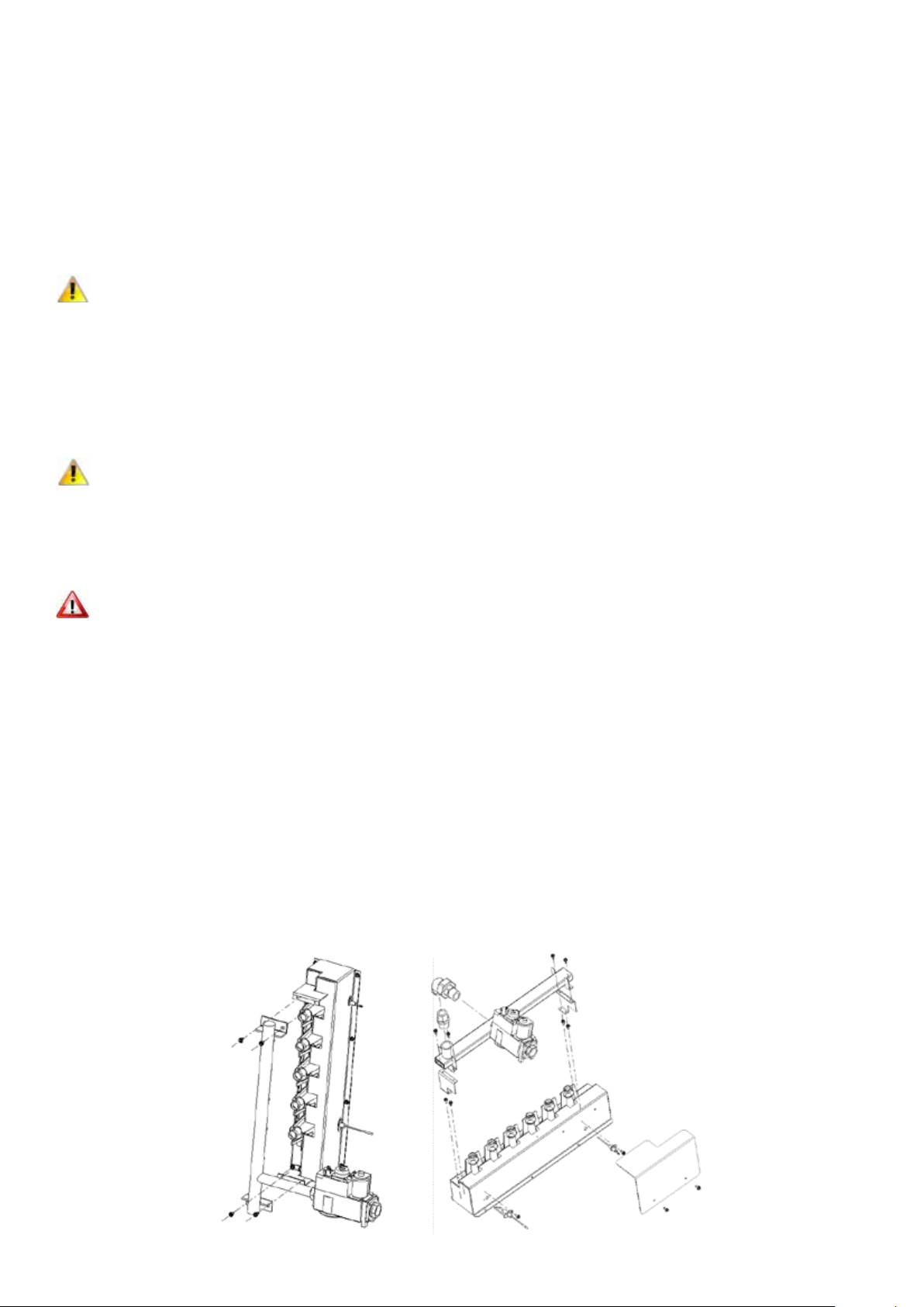
7.1.1 Instructions for burner removal
(see Figure 17):
1. Turn off the gas supply to the air heater.
2. Switch off the electricity supply to the air
heater.
3. Open the access door.
4. Disconnect the union in the gas supply
outside of the appliance.
5. Remove gas supply pipe from the
multifunctional gas control valve - remove
flame sensor wire from flame sensor &
high tension ignition wire from burner
relay.
6. The burner rack assembly is now visible
7.1Models 4024 - 4036 : At the bottom of
the burner rack assembly, remove the nut
that secures the burner box bottom.
At the top of the burner rack assembly,
remove the bolt that attaches the burner
rack assembly to the bracket. Lift the
burner rack/manifold assembly upward
(to clear the locating weld pins) and pull
the assembly out of the air heater.
7.2 Models 4050 - 4150M At the bottom & top
of the burner rack assembly, remove the 2
bolts that secures the burner rack to the
burner box bottom & top.
At the top of the burner rack assembly,
remove the 2 bolts that attaches the
burner rack assembly to the bracket. Lift
the burner rack / manifold assembly
upward (to clear the locating weld pins)
and pull the assembly out of the air
heater.
For clarity, the heater cabinet & other parts
are not illustrated; do not remove the burner
box assembly from the heater.
7.1.2 Instructions for re-assembly:
1. Reverse the procedure for removal making
sure that all parts are installed correctly.
2. Check that all components are secure.
3. When lighting, always follow the lighting
instructions on the air heater.
Note: After any service work has been carried out, the
air heater must be fully commissioned. See section 5 of
this document.
4024 - 4036
16
Figure 17. Removing the burner rack/manifold assembly
4050 - 4150M
Page 17
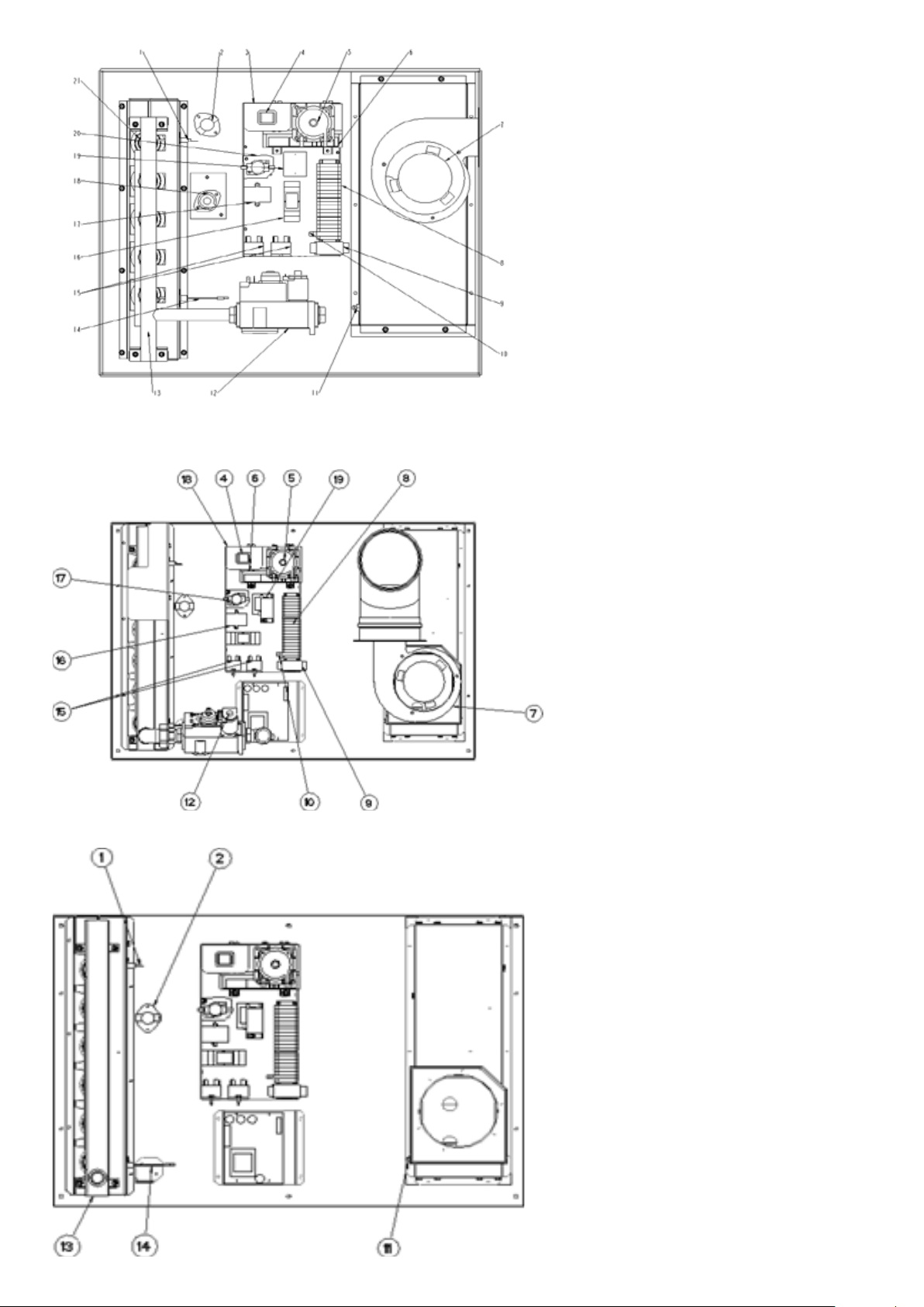
Figure 18. Removing the burner rack/manifold assembly
1. Flame sensor
2. LC1 limit control (without reset)
3. Electrical wiring panel
4. Reset lockout signal lamp
5. Differential pressure switch
6. Burner control relay or ignition controller
7. Flue gas extractor for combustion products
8. Electrical connectors
9. Time delay relay
10. Fuseholder with fuse
11. Differential pressure point
12. Combination gas valve with pressure
regulation
13. Manifold & injectors
14. Ignition electrode
15. Relay K1.1 (not for UK/IE)
16. Relay K1.2 (not applicable on
17. RHC 4000 DJL/RJL)
18. Relay main ventilator (not applied on RHC
4000 DJL/RJL)
19. Electronic net filter
20. LC3 max limit controller with manual reset
21. 3VA separation transformer (not for UK/IE)
22. Fan control relay
23. Tube burner
Figure 19. View of the control compartment (4050 - 4100)
17
1. Flame sensor
2. LC1 limit control (without reset)
3. Electrical wiring panel
4. Reset lockout signal lamp
5. Differential pressure switch
6. Burner control relay or ignition controller
7. Flue gas extractor for combustion products
8. Electrical connectors
9. Time delay relay
10. Fuseholder with fuse
11. Differential pressure point
12. Combination gas valve with pressure regulation
13. Manifold & injectors
14. Ignition electrode
15. Relay K1.1 (not for UK/IE)
Relay K1.2 (not applied in case of modulation
16. Electronic net filter
17. Fan control relay
18. LC3 max limit controller with manual reset
19. 3VA separation transformer (not for UK/IE)
Figure 20. View of the control compartment (4050 - 4100)
Page 18
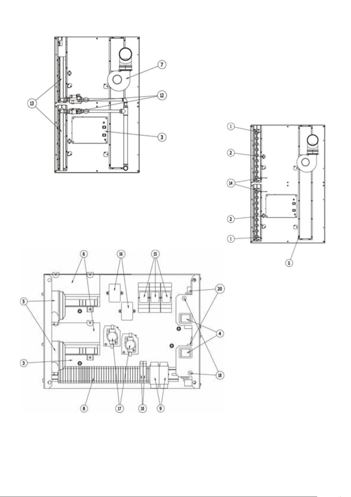
Figure 21. View of the control compartment RHC 4000(M) DJL
Figure 23.
Figure 22.
1. Flame sensor
2. LC1 limit control (without reset)
3. Electrical wiring panel
4. Reset lockout signal lamp
5. Differential pressure switch
6. Burner control relay or ignition controller
7. Flue gas extractor for combustion products
8. Electrical connectors
9. Time delay relay
10. Fuseholder with fuse
11. Differential pressure point
12. Combination gas valve with pressure regulation
13. Manifold & injectors
14. Ignition electrode
15. Relay K1.1 (not for UK/IE)
Relay K1.2 (not applied in case of modulation
16. Electronic net filter
17. Fan control relay
18. LC3 max limit controller with manual reset
19. GM 44
18
Page 19
7.2 Burner injectors
1. Carry out steps described in section 7.1.
2. Unscrew the main burner injectors.
3. Re-fit new injectors.
4. Re-assemble in reverse order.
7.3 Ignition system
To access the ignition system, follow steps
1 to 3 in section 7.1.
Igniter
Refer to Figure 1818, 20, or 22 and locate
the igniter (on the side of the burner rack).
Disconnect the wire, remove the screw and
the igniter. Clean with an emery cloth.
Note:
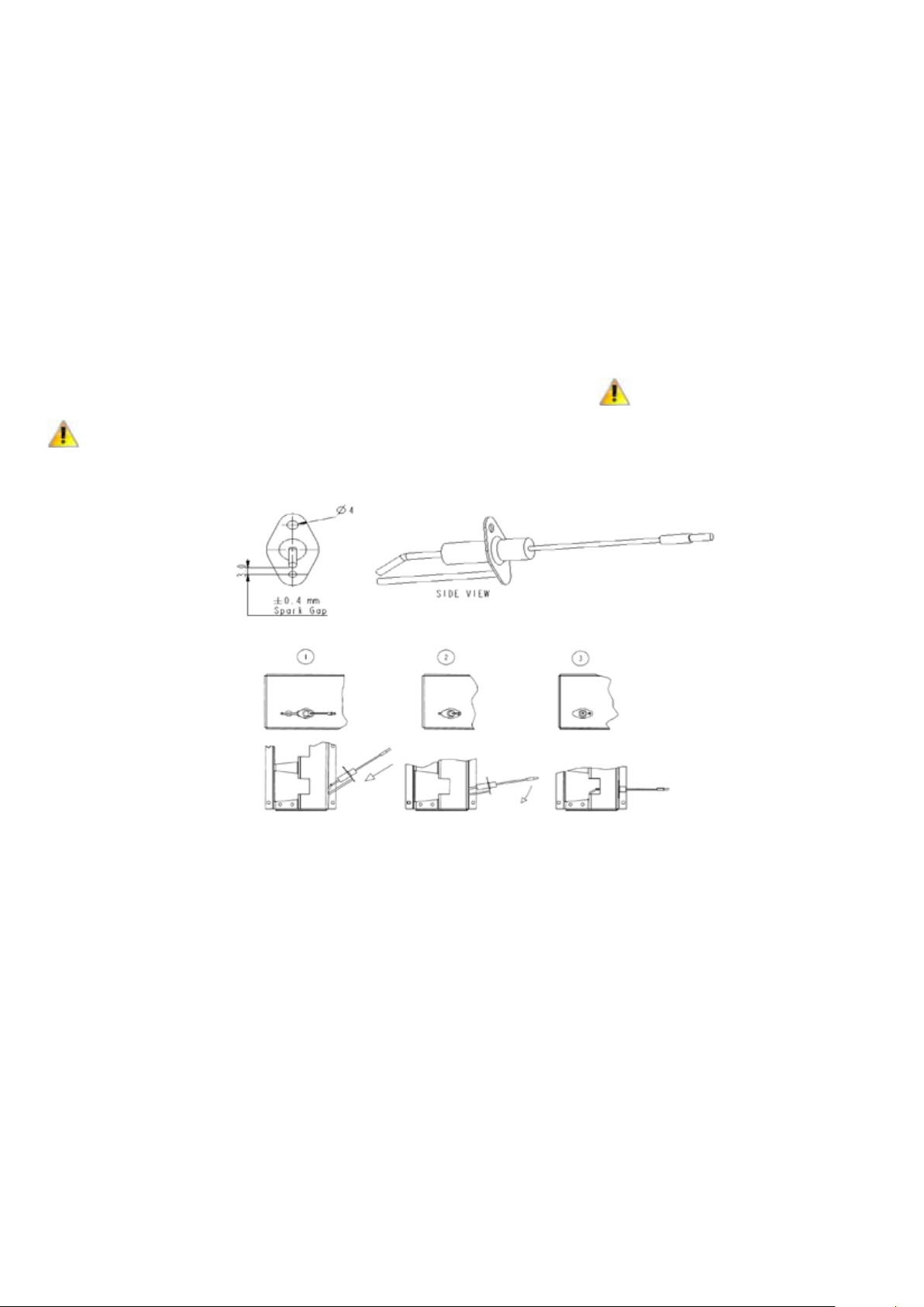
Spark gap must be maintained to 3.0mm See
Figure 24 on page 19. When re-assembling the earth
wire must remain attached to the igniter. We refer to
Figure 255 for installing the igniter.
Due to high voltage on the spark wire and
electrode, do not touch when energized.
CAUTION
See hazard levels.
Flame sensor
Refer to Figure 15, 18, 20, or 22 and locate
the flame sensor. Disconnect the wire,
remove the screw and the flame sensor.
Clean with an emery cloth.
Ignition controller
The enclosed integrated circuit
monitors the operation of the burner
including ignition. Do not attempt
to dismantle the ignition controller.
Each heating season lead wires
should be checked for insulation
deterioration and good connections.
Proper operation of the direct spark
ignition system requires a minimum
flame current of 1.0 µA when
measured with a micro ammeter.
For further information and checkout
procedure of the direct spark ignition
system, refer to the manufacturers
control operating instructions a copy of
which is supplied with the air heater.
7.4 Multi-functional gas control valve
1. Ensure gas supply to the air heater is
turned OFF.
2. After the air circulation fan has stopped,
switch OFF the electricity supply to the air
heater.
3. Mark for future identification and
disconnect the wires connected to the
valve.
4. Disconnect the gas service union between
the control valve and the gas service tap.
Remove the gas control valve.
5. Re-fit a replacement valve making all of the
required connections.
6. Carry out complete commissioning
procedure prior to placing the appliance
back into service as outlined in section 5.0.
The gas control operating valve is the
prime safety shut-off. All gas supply lines
CAUTION
must be free of dirt, scale, etc. before
connecting to the air heater thus ensuring
positive closure of the control valve.
7.5 Thermal overheat (limit) controls
If it is determined that the thermal overheat
control needs replacing, use only Reznor
authorized replacements that are designed
for this appliance.
To gain access to the control, open the
hinged controls compartment access
door. Refer to Figures 18 through 23 for
control locations. The control near the
top of the air heater is a disc type control.
The lower one is a capillary type one
with a capillary tube that extends into
the heat exchanger area. To remove the
controls, disconnect the wires leading
to them, remove the fixing screws and
lift clear of the inner-casing panel.
Note:
The capillary control is fitted to a bracket. With the
bracket removed from the air heater, remove the control
from the bracket.
19
Figure 24. Igniter assembly
Figure 25. Installing the igniter
When replacing the capillary control be
careful not to damage the capillary tube
by kinking. Make bends with a generous
radius (± 25mm). When replacing the disc
type control never manually attempt to
operate the disc by pushing on the disc.
Doing so will alter the calibration and could
be hazardous.
7.6 Combustion air control pressure
switch
If it is determined that the air differential
pressure switch needs replacing, use only
authorized replacements that are designed
for the air heater being serviced. These
switches are calibrated to operate at the
designed combustion airflow duty for each
appliance size in the product range
7.7 Combustion air fan (venter)
1. Ensure gas supply to the air heater is
turned OFF
2. After the air circulation fan has stopped,
switch OFF the electricity supply to the
air heater.
3. To gain access to the fan open the controls
compartment access door - refer to figures
18, 19, or 21 for location. Mark for future
identification and disconnect the wires
connecting the fan motor at the terminals
on the main wiring junction.
4. Remove combustion air fan and clean as
necessary using a wire brush and solvent
to remove sticky residues.
5. Re-assemble and check for free rotation
before proceeding to test the appliance.
Page 20
no
yes
yes
no
no yes
yes
no
no
yes no yes
no
yes
yes
no
no yes
no
yes
yes
check pressure
switch
Is there continuity
between 7 & 9?
Does the power venter
operate?
Is there 230V between
L&N?
Is there 230V between
1 & N ?
Connect or replace
tubing
Correct fault
Is the pressure tubing
connected & in sound
condition?
Clean the venter
wheel
Is there 230V between
8 & N ?
Is power venting
operating?
Reset limit control
Check venter motor
Replace pressure switch
Is the thermostat above
room temperature and if
used is the time
clock"ON"
Set thermostat above room
temperature & if used
make certain the time
clock is ON
Is there continuity
between terminals 8 & 7
Check electronic
ignition control
Is there a restriction in
the flue pipe or inlet grill
Is the wheel dirty
Determine what caused
the limit to trip
Place into normal
operation
Check the mains
Check the time/tempeature
control
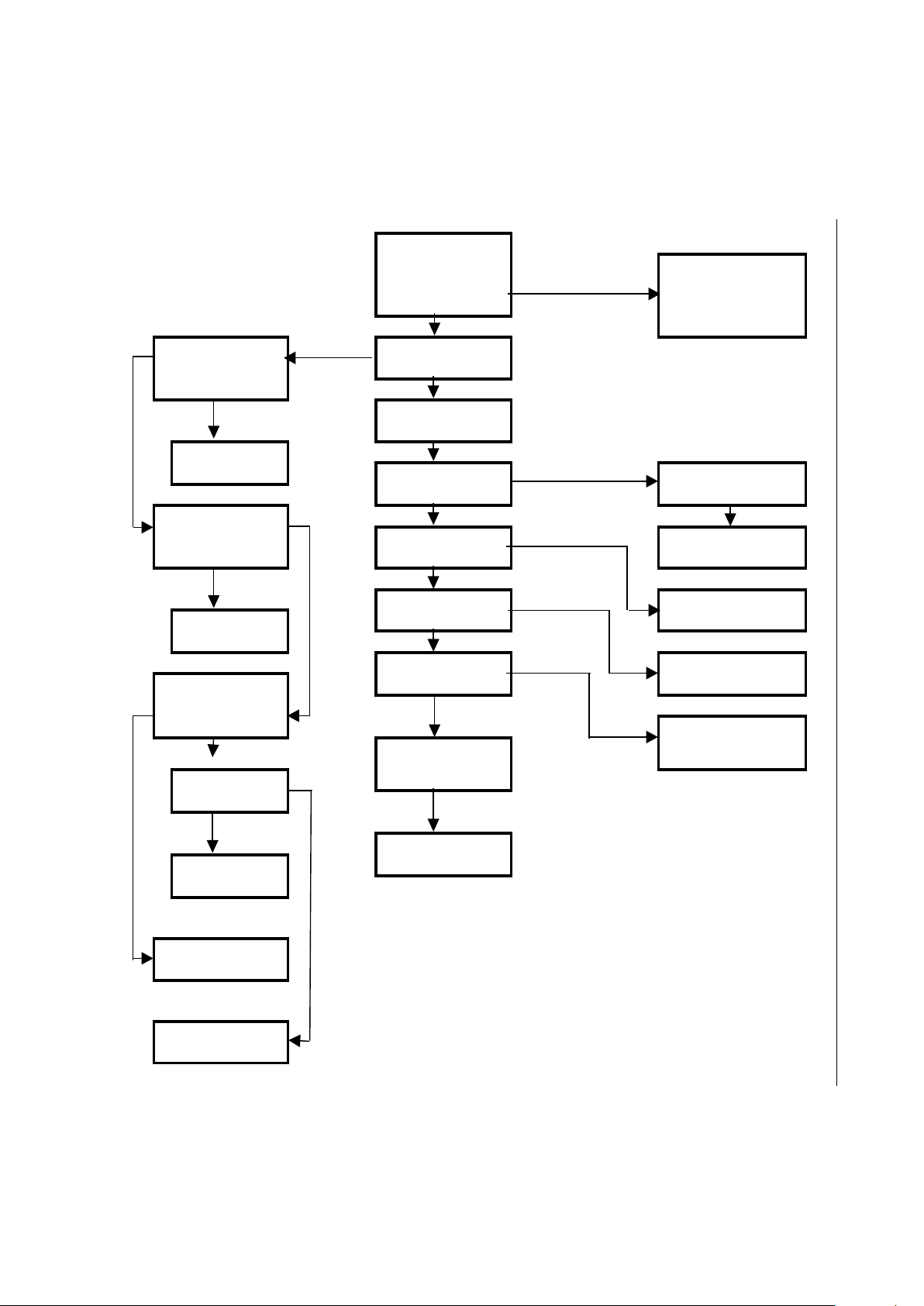
8. Fault Finding
8.1 Main Fault Finding Chart - Lockout Indicator Light Is "Off", But Air Heater Will Not Operate
WARNING Fault finding may only be carried out by appropriately qualified persons
20
Page 21
no
yes
no yes
no no
yes
no
yes
yes
no
yes
no
no
no
Check electronic
ignition control
Place in normal
operation
check multi
functional
gas valve
Check electronic
ignition control
Check flame signal. Is
it greater than 1,0
micro Amps?
Check electronic
ignition control
Spark visible, still
no flame
Remove corrosion
& scale from flame
sensing rod & clean
ceramic insulation
Is there 220 to 240V
between terminals
5 & N
check
electronic
ignition
control
During 5" trial for
ignition is a spark
visible?
Check flame signal
using micro amp
meter. Is signal greater
than 1,0 micro Amps?
Check spark gap
and ceramic &
check spark wire
& connector
Is a spark visible ?
During 5" trial for
ignition is a flame
visible in this view
port?
Is polarity of mains
correct?
Correct polarity
Correct the gas
supply pressure
Does the inlet gas
pressure agree with
the data badge
Wait 15" and press
reset button
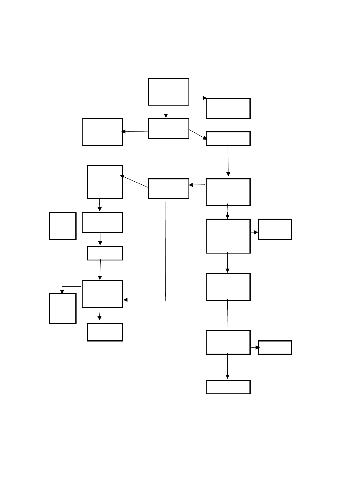
8.2 Ignition Controller Lockout Indicator Light Repeatedly Comes "On"
WARNING: Fault finding may only be carried out by appropriately qualified persons
21
Page 22
yes
no
yes
no
yes
yes
no
yes
no
no
yes
yes
no
Does the fan control
energize the fan motor
in less than 75"?
Check for excessive
main burner pressur
Does the fan
motor operate?
Has any non-factory authorized air distribution
device been placed on the heater? Is there excessive
static pressure in the ductwork? Did the motor overload
trip?
Consult fan
fault finding
Remove the
restriction
Are filters
clean?
clean filters
Adjust thermostat
temp. setting above
ambient to energize fan
& gas solenoid valve
Replace
the motor
Does the limit trip
before the fan is
energized?
Place system in normal
operation
Consult fan
fault finding
Is there 220-240V at
terminals N and 3?
no
no yes
yes
Adjust thermostat temperature
setting above ambient to
energize the fan and the
fan solenoid valve
Does the fan
operate ?
Is there 220-240V
at terminals N & 3?
Replace the
fan start relay
Replace fan
motor
Place the
system in
normal
operation
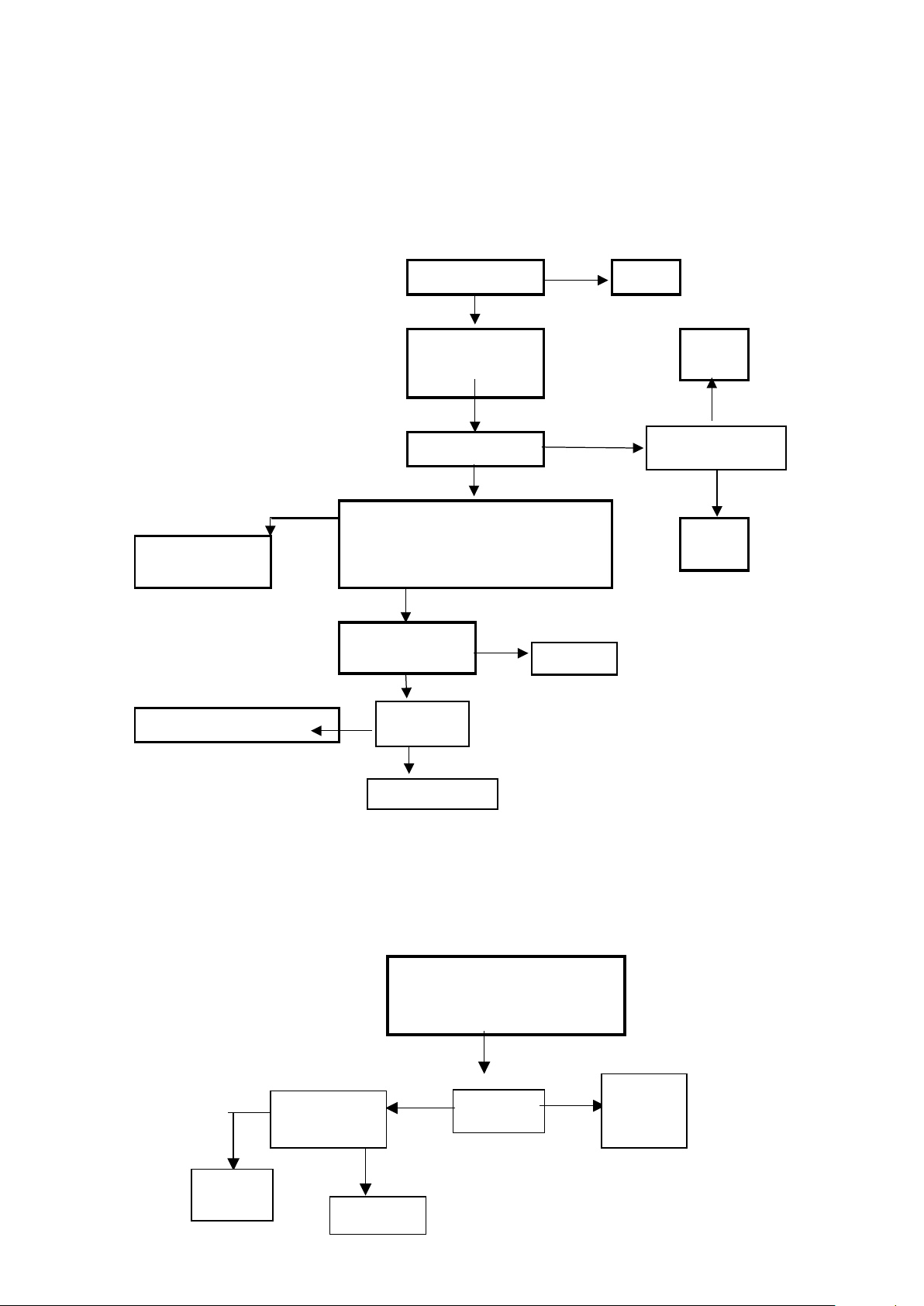
8.3 Limit Control Fault Finding Chart (Limit Control Trips)
WARNING: Fault finding may only be carried out by appropriately qualified persons
Note: RHC 4000(M) DJL air heaters are equipped with 2 limits (a recycling limit and a manual reset limit). During normal operation, neither limit should trip even if the main
electric supply is interrupted during operation. In the event of motor failure, the recycling limit will trip opening the gas valve.
8.4 Fan Fault Finding Chart
WARNING: Fault finding may only be carried out by appropriately qualified persons
22
Page 23

9. Parts List
Description Type Part number Application Settings
30-60617-120 4024 05 120 Pa off
30-60617-120 4030 06 120 Pa off
30-60617-88 4036 08 88 Pa off
30-60617-165 4050 06 165 Pa off
Differential pressure switch S3
Thermal overheat control (limit) LC1 T.O.D 60T 11 201614 03-400US-01 All 170F out 130F in
Thermal overheat control (limit) LC3
Relay K1.1
Relay K1.2 Potter & Brumfield T92 S11 A22 30-61742-240V 4024-4036
Combustion fan
Modulating gas valve
Fan delay control (K1.1) FCR TOD 12S 20 LX-2578A 03-25167
Modulating controller
T.O.D 10H14 212557
IMIT LS1
Thermodisc 12 S 20
AACO motor + wheel + case
EBM G2E160 fan assembly
Honeywell VK4105A with Modureg
Honeywell VR46 with Modureg
GM44 30-61511-330-01 All
30-60617-146 4060-07 146Pa off
30-60617-155 4075 09 155 Pa off
30-60617-115 4100-12 115Pa off
30-60617-82 4125M 15 82 Pa off
30-60617-82 4150M 18 82 Pa off
03-400US-03
03-24959
03-25167 4024-4036 20–60 seconds 60–120 seconds
36-79094
20-25745
03-25141-M
03-35145
4024–4036
4050-4150M
4024-4100
4125M-4150M
4024-4030
4036-4150M
240F out
96°C - 6
Reset
Reset
X-baffle
40mm 1022961 4024-4036
45mm 1001978 4050-4150M
Burner Inshot 1002831 All
Ignition controller Brahma 03-25322 All
Ignition electrode ER Channel products 03-400US-42 All
Flame sensor electrode IS Channel products SCS43 All
Filter 2.0A 30-61747 All
23
Table 12 – Parts list
Page 24

10. User Operating Instructions
How the air heater works:
Gas is burned by an atmospheric burner
that fires into a heat exchanger. The gas
burner is controlled by a double gas valve
via an electronic burner control, which
is actuated automatically via external
controls i.e. a room thermostat and/or a
time switch. The burner is ignited by a
spark igniter. When the burner fires and
warms the heat exchanger, the heat is
sensed by a thermally actuated fan control
which switches on the fan (in case there
is no constant running fan) when the
air temperature has reached its preset
operating level.
At the end of a heating cycle the burner is
switched off, the air circulation fan will
continue to run until the air heater has
cooled to a safe condition. Thereafter the
fan will remain off until the next cycle is
initiated.
Safety:
1. Flame failure is detected by the
ionization probe which is the sensor and
will immediately result in gas valve shut
down.
2. Safety against overheating is assured
by two overheat controls. The first is
an automatic recycle control which
protects against low air flow i.e. clogged
air ways, fan failure etc. The second,
which is set to a higher level than the
first one, is a control which locks out
and switches off the burner in the event
of gross overheating for any reason.
Manual intervention is necessary to
reset this control device. Resetting of the
automatic burner control may also be
required.
To light the heater:
1. Turn on the gas supply to the air heater.
2. Switch on the electricity supply to the
air heater.
3. Ensure time switch (if fitted) is set to a
'ON' cycle.
4. Adjust control/room thermostat to
desired temperature.
5. Air heater will light automatically when
the room thermostat calls for heat after
+/- 30 seconds.
6. If the appliance does not light:
6a. Check that the burner control does
6b. Check if thermal overheat control
7. If the thermal overheat control requires
resetting and doing so restarts the air
heater, wait until the appliance warms
to thermal equilibrium, to ensure the
overheat control does not lock out again.
If it does and the return air temperature
near the heater is less than 30°C, then
switch off the appliance and call for
service. If the return air temperature is
over 30°C, take appropriate action to
reduce the ambient temperature near the
air heater.
Air circulation:
The space heating process is for
air to be circulated through the
appliance whereby it gains heat from
a heat exchanger. The air is directly
discharged into the space to be heated.
The air is eventually recirculated.
Therefore it is very important that an
unobstructed path for the circulation
of the air will be maintained.
not require resetting. An indicator
light glows at the back panel of the
appliance and on a remote control if
fitted. Reset by pushing reset/button
on appliance or the remote control.
requires resetting
Maintenance:
1. Maintenance and service must only be
carried out by appropriately qualified
persons
2. It is in your interest to ensure proper
service and maintenance is carried
out at a regular basis. Periods between
service are dependent upon the local
environment where the heater is
installed. All gas appliances should be
serviced at least once a year.
3. In case of any damage to the appliance,
it must be shut down completely and
checked by an appropriately qualified
person.
4. In the event of difficulties in resolving
any of these matters, please do
not hesitate to contact the official
distributor.
Never switch off electricity supply to the
air heater without first closing the gas
WARNING
tap.
24
Page 25

11. Health & Safety Statement
11.1 General
The manufacturer hereby provides the
following information on substances
hazardous to health.
Product range reference RHC
4000(M) Series air heaters.
11.2 Cautionary note
During first firing some smoking may
occur,this is due to the burning off of
protective/lubricating oils used during
appliance production.Most of this will
have been removed during the production
testing process.It is a wise precaution
to ensure that adequate ventilation
is provided during the initial firing
and throughout the commissioning
period,this is particulary important
if the discharge air is to blow into a
confined space. This smoking does
not constitute a poison hazard.
11.3 Declaration
RHC products contain no asbestos;
copper is not employed in gas carrying
components; solder which has a melting
point below 450°C is not used; paints for
corrosion protection and decoration are
heat cured and contain no lead.
The above appliances meet the Electrical
Safety requirements oF EN 60335-1.
11.4 Miscellaneous
Small quantities of adhesives and sealants
used in the product are dried and cured and
present no known hazard.
11.5 Insulation and Seals
Material: Alumino - silicon fibre - crane
glass Description: Tapes
Known hazards: Some people can suffer
reddening and itching of the skin. Fibre
entry into the eyes will cause foreign body
irritation. Inhalation will cause irritation to
the respiratory tract.
Precautions: Wear protective gloves
when handling. People with a history of
skin complaints may be susceptible to
irritation.
Dust levels are only likely when
the material is abraded.
11.6 Thermostat. (Thermal overheat
(limit) control LC3) Material:
Illuminating Kerosene.
Description: Sealed phial contains a small
quantity in liquid form.
Recognition: Colourless liquid, paraffin oil/
petroleum hydrocarbon odour.
Characteristics: Non-corrosive, flammable
with no poisonous reference-CH poison
Class 3 Precautions: Avoid handling. This
product can irritate and defat the skin.
Prolonged contact may cause dermatitis.
Avoid breathing vapour.
Avoid eye contact. Do not ingest.
First Aid: Skin. Wash thoroughly with
soap and water. Eyes. Rinse immediately
with copious amounts
of clean water.
Ingestion: Seek medical advice.
Note: If skin irritation persists seek medical advice.
11.7 Electrolytic Capacitor
Two types are used by random selection:
Recognition: 1. Plastic enclosure
2. Aluminium enclosure
Material: Contained liquid electrolyte
Known hazards: Electric shock
possible if charged.
Precautions: Discharge to ground/earth. Do
not incinerate.
First Aid: Treat for electric shock if affected.
25
Page 26

12. ErP Information Requirements
Information requirements for warm air heaters Commission Regulation (EU) 2018
B1 warm air heater: [NO]
C2 warm air heater: [NO]
C4 warm air heater: [NO]
Type of fuel: [G20]
Model: 4024-05 4030-06 4036-08 4050-06 4060-07 4075-09 4100-12 4125M15 4150M18
Item: Symbol: Units
Capacity:
Rated heating capacity: Pnom [kW] 24.0 29.9 36.4 50.2 60.6 74.1 96.9 125.5 150.8
Minimum capacity: Pmin [kW] 11.4 14.3 17.2 24.0 28.7 35.2 46.1 60.8 71.9
Electric power consumption:
At rated heating capacity: elmax [kW] 0.153 0.153 0.153 0.153 0.153 0.153 0.153 0.282 0.282
At minimal capacity: elmin [kW] 0.153 0.153 0.153 0.153 0.153 0.153 0.153 0.282 0.282
In standby mode: elsb [kW] 0.015 0.015 0.015 0.015 0.015 0.015 0.015 0.015 0.015
81.8 81.6 82.7 81.0 81.3 81.0 80.7 81.8 82.4
78.1 78.3 78.2 77.4 76.9 76.8 76.8 79..3 78.7
[%]
[%]
ƞth,nom
ƞth,nom
Useful efficiency at minimum capacity:
Other items:
Useful efficiency:
Useful efficiency at rated heating capacity:
Envelope loss factor: Fenv [%] 0.0 0.0 0.0 0.0 0.0 0.0 0.0 0.0 0.0
Flame consumption: Pign [kW] 0.0 0.0 0.0 0.0 0.0 0.0 0.0 0.0 0.0
NOx [mg/kWh] 65 35 55 73 80 95 69 66 63
Emissions of nitrogen oxides [input energy
[%] 95.5 95.0 96.3 95.4 95.4 95.4 95.5 92.9 93.1
ƞs,flow
(GCV)]:
Emission efficiency:
[%] 72.0 72.2 73.5 72.3 72.1 72.1 72.2 72.0 72.0
ƞs
ErP seasonal space heating energy
efficiency:
[%] 90.8 90.6 91.8 90.0 90.2 89.9 89.6 90.8 91.5
Thermal efficiency at rated heating capacity
ƞ
[NCV]:
26
Page 27

NORTEK GLOBAL HVAC (UK) LTD
Fens Pool Avenue
Brierley Hill
West Midlands DY5 1QA
United Kingdom
Tel +44 (0)1384 489250
Fax +44 (0)1384 489707
[email protected]
www.reznor.eu
Nortek Global HVAC is a registered trademark of the Nortek Global HVAC limited. Because of the continuous product innovation, Nortek
Global HVAC reserves the right to change product specification without due notice.
This document replaces the previous, Manual Part No D301155 Issue B
Current full Part No. Reznor, RHC 4000 EN April 19 D301155 Issue C
 Loading...