

Page 1

NOTICE:
The information contained on the following page(s) was produced
prior to May 1, 2014. On that date Reznor became part of
Nortek, Inc.
References to any other company afliations are no longer valid.
This manual refers to Reznor brand products that have been
discontinued for more than 10 years.
Some replacement parts may no longer be available from
our suppliers. Compatible parts may be substituted.
Please contact your Reznor Representative
with specic questions.
©2014 Reznor, LLC. All Rights Reserved.
Trademark notice: Reznor is registered in at least the United States.
0514 PDF Form Cover2
Page 2
Indoor or Outdoor, Gas, Direct-
Fired, Makeup Air/Heating Systems
®
Index Page
Air Pressure ..................................... 4
Air Pressure Switches.................... 10
Blower Bearings ............................. 3
Burner ........................................ 4, 11
Circuit Indicator Board.................... 4
Control Locations............................ 8
Damper Motor .............................. 19
Direct-Fired Burner....................... 11
Dirty Filter Switch ........................ 19
Door Switch................................... 17
Drive Components .......................... 2
Electronic Circuit Board with
Diagnostic Lights ........................ 8
Emergency Cut Off ......................... 9
Evaporative Cooling Module ........... 5
Filters .............................................. 3
Firestat ........................................... 20
Freezestat ....................................... 20
Gas Control Systems .................... 11
Gas Pressure ................................... 3
Gas Pressure Switches................... 17
Ignition System .............................. 11
Inlet Air Controls ........................... 17
Limit Control................................... 9
Maintenance Schedule ..................... 2
Maintenance Section................. 2-7
Maintenance/Service Access ........... 2
Manifold Arrangements ................ 16
Operation/Service Section ...... 8-24
Outside Air Cutoff Control ............17
Photoelectric Smoke Detector ........ 20
Photohelic Pressure Sensor............ 19
Pilot Assembly ................................ 4
Potentiometer ................................. 19
Pressure Null Switch ..................... 19
Sensing Pressure Check................ 10
Troubleshooting ............................ 21
Wiring Diagram - In the main
electrical box on the unit
References:
Installation Manuals:
Model DV, Form RZ-NA I-DV
Model RDF, Form RZ-NA I-RDF
Model ADF(H), Form RZ-NA I-ADF
Replacement Parts Manual:
Form RZ-NA P-DV/RDF/ADF
or Form 740 for RDF; Form 741 for
DV, and Form 742 for ADF/ADFH
C E R T I F I E D
Operation/Maintenance/Service
Form RZ-NA O-DV/RDF/ADF
Obsoletes Form RZ-NA 440-OMS, 441-OMS, and 442-OMS
Applies to: Models DV, RDF, and ADF/ADFH
KEEP THIS BOOKLET FOR
MAINTENANCE AND
SERVICE REFERENCE.
FOR YOUR SAFETY
WARNING: The use and storage of gasoline or other flammable
vapors and liquids in the vicinity of this appliance is hazardous.
FOR YOUR SAFETY
If you smell gas:
1. Open windows.
2. Don't touch electrical switches.
3. Extinguish any open flame.
4. Immediately call your gas supplier.
WARNING: Improper installation, adjustment, alteration,
service, or maintenance can cause property damage, injury or
death. Read the installation, operation, and maintenance
instructions thoroughly before installing or servicing this
equipment.
WARNING: On makeup air heaters which also recir culate room
air, outside ventilation air must be provided in accordance with
the information shown on the heater rating plate.
Recirculation of room air may be hazardous in the presence of:
(a) Flammable solids, liquids, and gases;
(b) Explosive materials (e.g. grain dust, coal dust, gun powder,
etc.); or
(c) Substances which may become toxic when exposed to heat
(e.g. refrigerants, aerosols, etc.).
Operating/Maintenance/Service
The information in this manual applies to Model Series DV, RDF, and ADF direct-fired
heating/makeup air systems. As with any gas burning equipment, regular maintenance
procedures are required to ensure continued safety, reliability and efficiency of the installation.
If service is required, this system should be serviced only by a qualified service person.
Service information in this booklet is intended as a guideline for a qualified gas-fired
equipment service person.
Form O-DV/RDF/ADF, P/N 148385, Page 1
Page 3
DANGER: The gas burner in this dir ect gas-fir ed system is designed and equipped to pr ovide
safe, controlled complete combustion. However, if the installation does not permit the burner
to receive the proper supply of combustion air, complete combustion may not occur . The result
is incomplete combustion which produces carbon monoxide, a poisonous gas that can cause
death.
Always comply with the combustion air requirements in the installation codes and operating
instructions. The amount of air over the burner must be within the specified range. The burner
profile plates are set at the factory to match CFM requirements. Do not adjust the burner
profile plates without contacting the factory . F AILURE TO PROVIDE PROPER COMBUSTION
AIR CAN RESUL T IN A HEAL TH HAZARD WHICH CAN CAUSE PROPERTY DAMAGE,
SERIOUS INJURY, AND/OR DEA TH. Direct-fired installations should pr ovide for air changes
as required by the applicable installation codes.
MAINTENANCE
SECTION
Maintenance Codes
S = Safety (to avoid
personal injury and
/or property damage)
R = Continued Reliability
E = Efficient Operation
Maintenance
Schedule
This direct-fired makeup air system is designed to require only a minimum
amount of maintenance. Some maintenance procedures outlined in this Section require inspection only and some require action. Frequency requirements
of each maintenance procedure are listed in the Maintenance Schedule. Depending on the environment and the number of operating hours, more frequent inspection and/or cleaning may be required to certain components.
Although maintenance requirements are minimal, the routine maintenance procedures in this Section are necessary to ensure safe, reliable, and/or efficient
operation. The paragraphs which follow discuss the components and systems
that require routine inspection/maintenance. At the beginning of each paragraph, there is a code indicating why that maintenance procedure is necessary.
The legend for that code is shown on the left.
WARNING: Disconnect all power to the system before doing
any maintenance. Failure to do so may cause electrical shock,
personal injury, or death.
See Chart oLubricate bearings, Paragraph 1
Quarterly oCheck the filters, Paragraph 2
oCheck air pressure sensing tubes, Paragraph 4
Semi- oCheck blower belts, Paragraph 1
Annually oVerify gas pressures, Paragraph 3
oClean air pressure sensing tubes, Paragraph 4
oCheck indicator lights, Paragraph 5
Annually oCheck main burner and pilot assembly, Paragraph 6
1. Drive
R
Components
Form O-DV/RDF/ADF, P/N 148385, Page 2
The blower, motor and drive components are located in the blower cabinet.
Remove the panels required to access the component(s) being serviced.
1A. Blower Bearings
All blowers are Class I with pillow block bearings. Clean the fitting and add
type NLG-2 or -2 standard grade grease. Add grease with a handgun until a
slight bead of grease forms at the seal. Be careful not to unseat the seal by over
lubricating.
CAUTION: If the blower is unused for more than three months, the
bearings should be purged with new grease prior to startup.
Page 4
Recommended Bearing
p
p
Lubrication Schedule in
Months
FIGURE 1 - Belt Tension
3/4 (19mm)
Bearing Bore Diameter (Inches)
RPM
to 1000 6 6 6
1001 - 1 500 5 5 5
1501 - 2 000 5 4 5
1/2 to 1 >1 to 1-1/2 >1-1/2 to 1- 15/16
NOTE: If unusual environmental conditions
exist ( temperatures below 32°F or above
200°F; moisture; or contaminants ) more
frequent lubrication is required.
1B. Blower Belts
Check belts for proper tension and wear. Adjust belt tension as needed. Replace worn belts.
Proper belt tension is important to the long life of the belt and motor. A loose
belt will cause wear and slippage. Too much tension will cause excessive
motor and blower bearing wear. If adjustment is required, adjust belt tension
by means of the adjusting screw on the motor base until the belt can be depressed 1/2" to 3/4" (FIGURE 1). Tighten the lock nut on the adjusting screw.
Be sure the belt is aligned in the pulleys.
RE
2. Filters
Quantity and Size of
Filters by Model
3. Manifold Gas
S
Pressure
If the system includes filters, check the filters quarterly. Filters could be either
in an optional filter cabinet (DV/RDF/ADF) or in the optional inlet base (DV).
To access filters in a filter cabinet, remove the filter cabinet door panels. Clean
or replace as needed. If removed, be sure to put blockoff plates in filter rack.
If the filters are in the perimeter of the inlet base of a Model DV; they are twoinch permanent filters. Remove and clean the filters as needed.
Dis
Type
Thickness
Model RDF with Optional Filter Cabinet
1
2
3
Model ADF/ADFH with Optional Filter Cabinet
300
500
700, 1200
Model DV with Optional Filter Section
109, 112
115, 118
122, 125
Model DV with Inlet Base with Filters
109, 112
115, 118
122, 125
(5)12x30-5/8 (5)12x30-5/8 (10)10x16 (10)10x16 (5)12x32 (5)12x32
(5)12x20 (5)12x20 (5)12x20 (5)12x20 (5)12x20 (5)12x20
(5)12x25 (5)12x25 (5)12x25 (5)12x25 (5)12x26 (5)12x26
(5)12x25 (5)12x25 (5)12x25 (5)12x25 (5)12x25 (5)12x25
(5)12x30-5/8 (5)12x30-5/8 (5)12x32 (5)12x32 (5)12x32 (5)12x32
osable Permanent Pleated Disposable
1" 2" 1" 2" 1" 2"
- - (3)12x35 (4)12x35 - -
- - (4)12x35 (4)12x35 - -
- - (4)12x24 (4)12x24 - -
- - (12)12x35 (10)12x35 - -
- (4)16x16 (4)16x16 (4)16x16 (4)16x16 (4)16x16
- (4)16x20 (4)16x20 (4)16x20 (4)16x20 (4)16x20
- (6)16x20 (6)16x20 (6)16x20 (6)16x20 (6)16x20
- (6)16x25 (6)16x25 (6)16x25 (6)16x25 (6)16x25
- (16)16x16 (16)16x16 (16)16x16 (16)16x16 (16)16x16
- (6)16x25 (6)16x25 (6)16x25 (6)16x25 (6)16x25
- - - (8) 10x12 - -
---(8)15x20--
- - - (16)20x20 - -
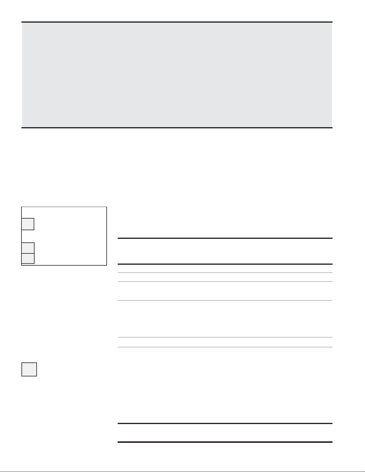
Semiannually, check the gas pressure to the burner and to the pilot. Measure
both manifold pressure and pilot supply pressure with the blower in operation. Verify against pressures listed on the rating plate.
Pilot
Regulator
Pilot Solenoid Valve
FIGURE 2 - Gas Pressure
Pilot Pressure Tap
Tap Locations
Valve
Gas
Supply
Inlet Pressure Ta
Valve
Regulator
Form O-DV/RDF/ADF, P/N 148385, Page 3
Manifold Pressure Tap
Page 5
MAINTENANCE SECTION (cont'd)
4. Air Pressure
S
5. Circuit
R
Indicator
Board (check
lights)
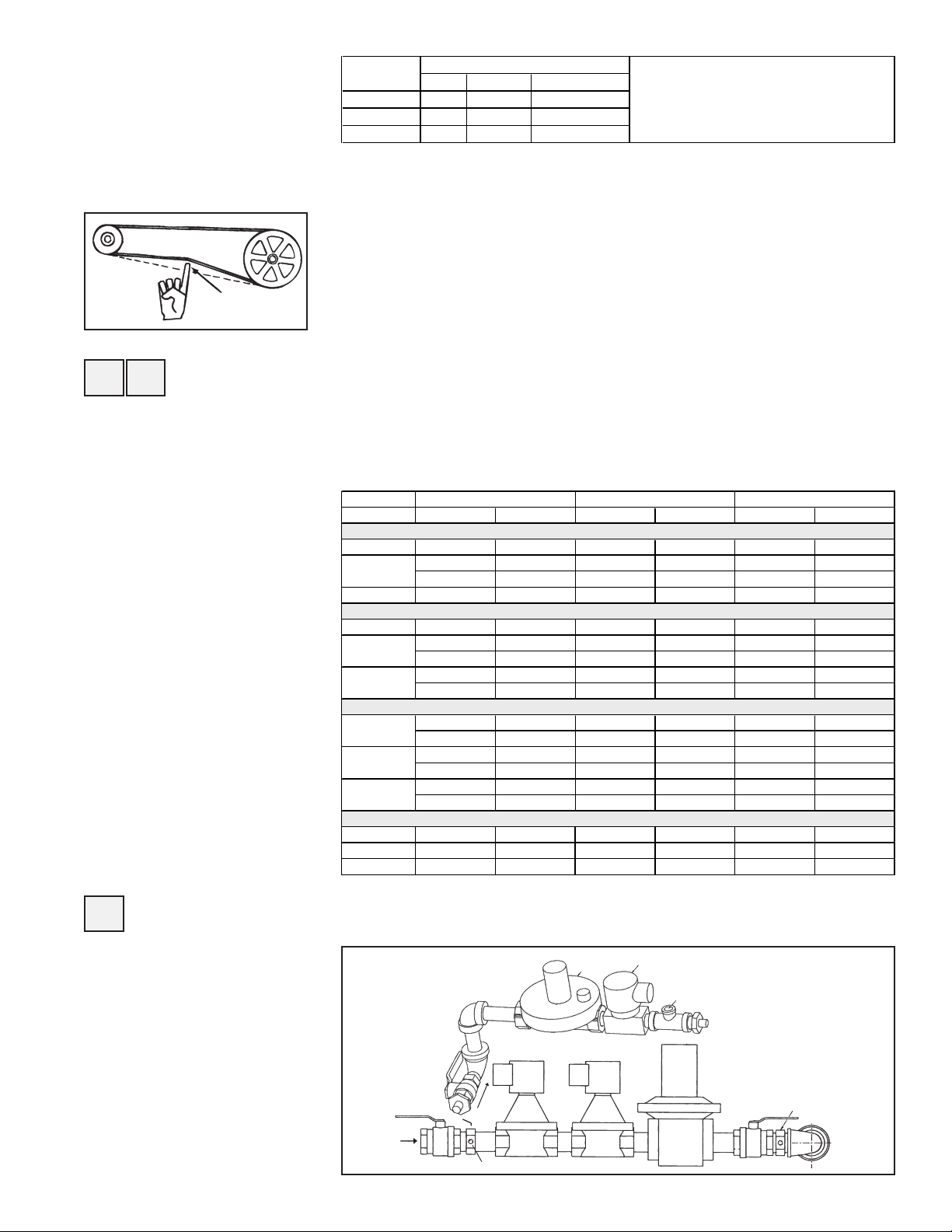
FIGURE 3 - Circuit
Indicator Board,
P/N 151263
Profile plate sensing tubes should be checked quarterly and cleaned no less
than semiannually. If the sensing tubes become even partially blocked, false
pressure readings may be relayed. To clean, remove the screened end caps.
Clean the screens and the tubes, if necessary. Replace the cleaned end caps.
Check the pressure differential across the profile plate using a slope gauge.
Air pressure differential should be between -.25" and -.75" w.c.
To attach the slope gauge, open the control compartment door panel. Just
below the junction box, locate the tubing connections. Remove the cap at
each connection and attach the slope gauge using two field-supplied 1/4" x
1/8" female NPT barbed tubing connections. For instructions on measuring air
pressure, see Service Section, Paragraph 9.
The circuit indicator board is located in the control compartment electrical
box (See FIGURE 7). Check operation of all indicator lights by switching
lights that are not lit with one that is currently lit. Replace any burned out
indicator bulbs (P/N 125189).
Row of Bulbs
Check bulbs not
lit with other
bulbs; replace
any burned out
bulbs.
S
6. Main Burner
and Pilot
Assembly
CAUTION: W ear eye
protection while
pressure cleaning and
drilling.
WARNING: Do not
enlarge burner ports or
performance may be
drastically affected.
Form O-DV/RDF/ADF, P/N 148385, Page 4
For the most part, the burner and pilot are self cleaning. However, if the application is extremely dirty or dusty, cleaning of the burner and pilot may be
necessary. Inspect the burner annually. Follow these instructions. If it is necessary to replace any parts, use only factory-authorized replacements.
1)Turn off the gas and power supply to the system.
2)Remove the door panels in the burner/control cabinet. Locate the pilot.
3)Disconnect the two ignition wires (male and female quick connections)
and disconnect the flame sensor lead at the burner. Remove the setscrew
located in the ignitor tube (setscrew holds the brass bushing in place).
Carefully remove the brass bushing and the ignitor.
Check the hot surface ignitor for cracks or unusual deterioration. Check
the flame rod for integrity. Replace the flame rod (P/N 131188) and/or the
hot surface ignitor (P/N 121865) if not in good condition.
4)Clean the burner and pilot by back-flushing, using high pressure air (40-
80 lbs). Continue until dust particles are completely expelled from both
the upstream and downstream sides of the burner.
If air pressure does not unplug burner orifices or pilot tube, drill burner
orifices with a Size #50 drill and/or pilot tube with a Size #55 drill.
Inspect the upstream and downstream sides of the mixing plates. Remove
any accumulation of scale or foreign material with a wire brush. If any
mixing plate fasteners are loose or missing, tighten or replace. Always use
zinc plated or stainless fasteners.
If any cracks are present, replace that mixing plate. Because of the effect of
flame temperature on the metal, fasteners may be difficult to remove. Be
careful not to damage the gaskets that go between the mixing plates and the
Page 6
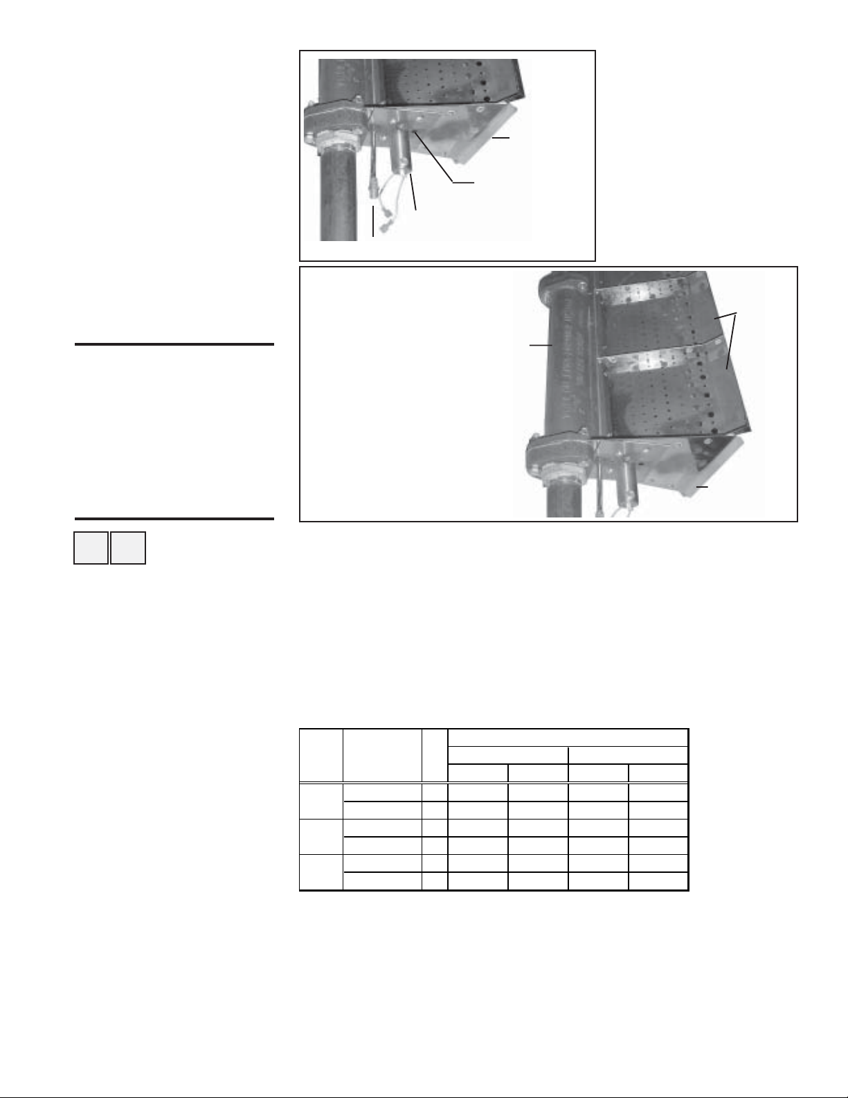
FIGURE 4 - Burner End
Plate showing Hot Surface
Ignitor
NOTE: Model RDF units
manufactured prior to 3/96
have a spark ignition system.
Clean ultraviolet sensor and
spark plug. Replace as
needed.
FIGURE 5 - Direct Fired
Burner
W ARNING: Burner
profile plates are
factory set to match
CFM requirements. Do
not adjust profile plates
without contacting your
Sales Representative
for technical assistance.
Flame Sensor
(not shown)
Ignitor
Location
Pilot Tubing
Burner - Full length of the
burner is made up of a series
of 6" or 12" burner sections in
a linear or oval configuration.
Burner
End Plate
burner body. The gaskets are
designed to overlap approximately 1/16" for airtight seal.
5)Follow Steps in reverse
order to re-install the pilot
assembly. Close all panels
and check for proper
operation.
Mixing
Plates
Burner
End Plate
RE
7. Optional
Evaporative
Cooling Module
(ADF/ADFH only)
Instructions for Replacing
Evaporative Cooling Media
Media - Over time, excessive amounts of mineral deposits will begin to buildup
on the media. Annually, scale and dirt should be washed off the entering surface of the media. Remove the pad retainers and screen. (See Steps 1-3 and 68 of Media Replacement Instructions.) Clean the media using a garden hose,
mild soap, and a soft bristled brush. When the media becomes too clogged
with mineral deposits and dirt that it cannot be cleaned, the pads should be
replaced. The average pad life is approximately three cooling seasons.
Select the correct replacement part numbers and order media pads from your
Distributor. Follow the instructions below and remove and replace pads as
shown in FIGURE 6.
ADF /
ADFH
300 24 x 12 2 105985 106021 106037 106029
500 24 x 12 3 105985 106021 106037 106029
700/ 48 x 12 4 107190 107194 107199 107201
1200 48 x 8- 5/ 8
1. Remove the three sheetmetal screws that hold the top pad retainer in
2. Remove the three sheetmetal screws that hold the bottom pad retainer in
3. Disengage the screen retainers from the sides of the media.
4. Disengage inlet screen from media pads and remove.
5. Slide all media pads horizontally away from the cooling module until
Media Pad
Sizes
(inches)
24 x 7- 7/ 8
24 x 9- 5/ 8
place. Release the top pad retainer from the cooling module.
place. Release bottom pad retainer from the cooling module.
clear of bottom reservoir pan. Dispose of properly.
Qty
1
1
1
Replacement Part No. (e ach)
Cellulose Fiber Glass Fiber
6" 12" 6" 12"
105986 106022 106038 106030
105989 106025 106041 106033
107191 107195 107200 107202
Form O-DV/RDF/ADF, P/N 148385, Page 5
Page 7
MAINTENANCE SECTION (cont'd)
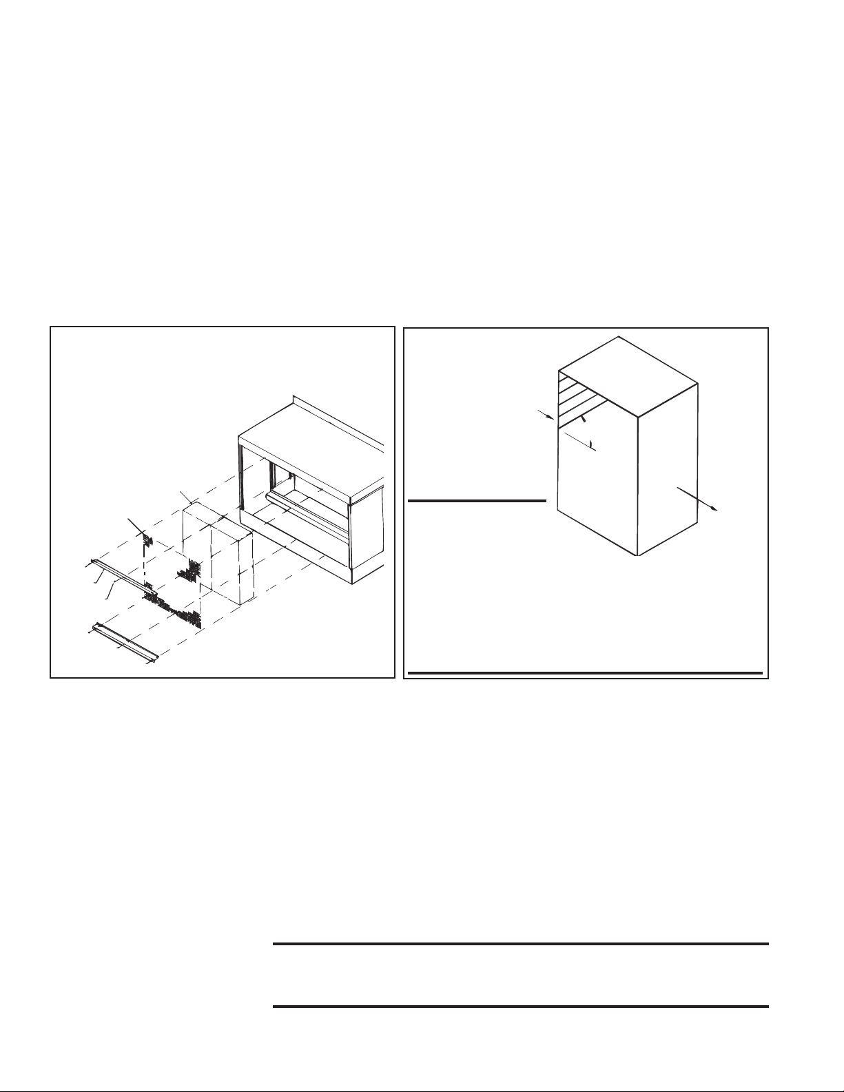
45°
Airflow
to Space
Outside
Airflow
7. Optional Evaporative Cooling Module (ADF/ADFH only) (cont'd))
Instructions for Replacing
Evaporative Cooling Media
(cont'd)
6. Replace media by sliding media pads over both support rails until back
stop is encountered. Media must be placed as shown in FIGURE 7.
7. Center screen on the incoming air side of the media.
8. Replace the two side screen retainers by fitting them between the side of
the media pad and the side of the cooling module. The retainers should
fit snugly, pinching the screen against the media pads.
9. Replace the bottom pad retainer by securing the retainer between the pad
and the reservoir pan. Fasten with the three sheet metal screws removed
in Step 2.
10. Replace the top pad retainer by securing the retainer between the pad
and top of the cooling module. Fasten with the three sheet metal screws
removed in Step 1.
FIGURE 6 - Removal and Replacement of
Evaporative Cooling Module Media
Pad
FIGURE 7 Media must be
installed
with 45°
angle sloping
downward
toward the
incoming outside
air.
Screen
Pad
Retainer
Screw
Other Evaporative
Cooling Module
Maintenance
IMPORTANT: The
media is made up of two
different sheets of cooling
material. Each sheet has its own unique angle.
When replacing the cooling media, BE CERTAIN
that the 45° angle slopes downward toward the
incoming outside air (as illustrated above). If the
media is not installed properly , water blowoff from
the media pads will occur .
Water Feed Line and PVC Distribution Piping - Annually, the water supply
line and PVC water distribution pipe should be flushed of debris and contaminants.
1. Remove the media pads following the media replacement instructions.
2. Remove the water feed line from the downstream side of the ball valve
and unscrew the water bleed line barbed hose fitting.
3. Force a fresh water supply through the water inlet hose and thoroughly
flush the distribution pipe.
4. Reassemble being careful to install media with air flow direction as shown
in FIGURE 7.
Water Pump and Inlet Basket Screen (applies to system with float and pump
control) -- Annually, the pump and inlet basket screen should be removed,
disassembled, and cleaned.
Form O-DV/RDF/ADF, P/N 148385, Page 6
WARNING: Do not expose pump motor or any part of the
electrical box to water. Evaporative cooling pump is NOT
submersible.
1. Disconnect the power supply to the unit.
Page 8
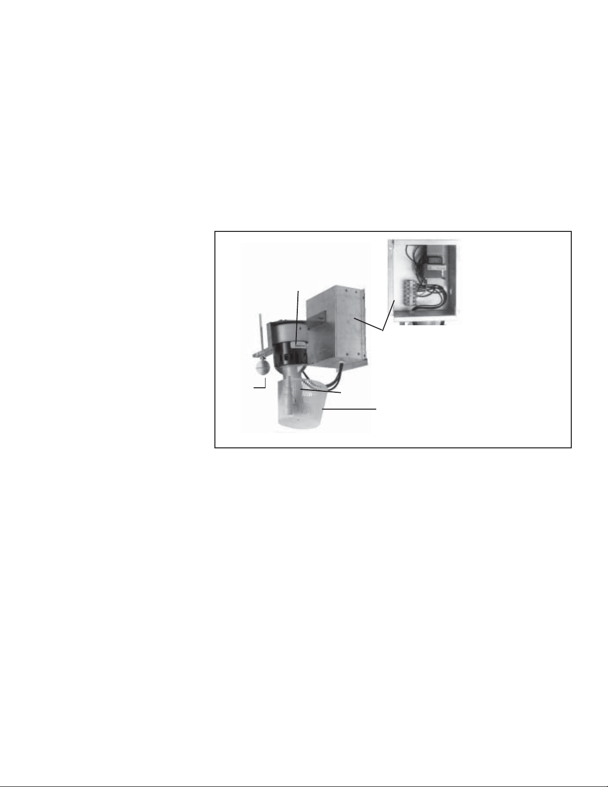
FIGURE 8 - Remove
Junction Box, Pump, and
Float Switch as an Assembly
(Actual assembly may not
appear exactly as in the photo.
Applies to evaporative
cooling module with float and
pump control system only . )
2. Remove the service panel and the junction box door. Disconnect the twoline voltage power supply wires from the terminal block inside the junction box.
3. Disconnect the water feed line hose from the upstream side of the ball
valve.
4. Unscrew the four sheet metal screws holding the junction box to the
cooling module. Remove the junction box-pump-float switch assembly
(See Figure 8).
5. Dislodge the inlet basket screen from the pump and clean any buildup of
debris and dirt. Carefully remove the base cover plate from the bottom of
the pump. Using a mild soap solution, wash all deposits from the inside of
the pump and remove all debris from the impeller.
6. Reassemble the pump. Replace the parts in exact reverse order, being
careful that everything is returned to its proper position.
Pump
Motor
Junction Box (Note: Only 208V unit
will have a transformer in the junction box.)
Float
Switch
Pump
Carefully remove basket and
snap-on cover plate to clean
pump.
REFERENCE: Evaporative Cooling Module Troubleshooting
Guide, Paragraph 20, page 23.
Form O-DV/RDF/ADF, P/N 148385, Page 7
Page 9

OPERATION/
SERVICE SECTION
Controls - Location,
Operation, and
Service
FIGURE 9 - Control
Identification and T ypical
Locations (Model DV is
shown as an example)
To service this system, it is necessary to understand the normal operation of
the controls and the function of the diagnostic circuit board. Refer to the electrical box drawing in FIGURE 9 and to the individual illustrations to identify
and locate each of the controls. The wiring diagrams for this unit are located in
the main electrical box.
WARNING: Service work on this system should only be done by
a qualified gas service person. The service information and the
troubleshooting guides are intended as an aid to a qualified service
person.
Control
Relays
Ignition
Module
Maxitrol Amplifier
or Signal Conditioner
(high ambient limit control)
Circuit
Board
Outside Air Cutoff
Bypass
Damper
Motor
Status Lights
Service
Switches
High
24-Volt Terminals
Low
Time Delay
Relay
24-volt Terminals
Return
Air
Damper
Motor
Transformer
Motor
Starter
Optional Dirty Filter
Pressure Switch
Standard Pressure
Switches
Relay for
Optional 2-Speed
Starter
Relay
NOTE: Wiring diagrams for the unit ar e located on the inside of the electrical box door.
8. Electronic Circuit
Board with Lights
FIGURE 10 - Diagnostic
Circuit Board, P/N 151263
Column of 13 indicator
bulbs; always replace
burned out bulbs, P/N
125189.
Form O-DV/RDF/ADF, P/N 148385, Page 8
Location: Control Compartment Electrical Box (See FIGURE 9)
Function: The diagnostic lights on the circuit board are designed to assist in
troubleshooting. When the system is operating properly, the lights on the circuit board are lit. If the system fails to operate properly, all lights on the circuit
board up to that one that represents the component or system that has failed
will be lit. For more detailed information, refer to the Troubleshooting Guide
in Paragraph 19.
Control Circuit Power
Control Switch Energized
Firestat Normal
Freezestat Normal
Starter Energized
Blower ON - High Air Pressure Normal
Blower ON - Low Air Pressure Normal
Manual and Auto Limits
Normal
Outside Air Cutoff Normal
Low Gas Pressure Normal
High Gas Pressure Normal
Pilot Valve Energized
Gas Safety Valve Energized
Line Voltage
Terminals
Page 10

Service: Replacing burned out bulbs is the only service required. If a bulb is
not lit, check the bulb by switching it with a bulb that is lit.
9. Limit Safety
Controls
FIGURE 11 - Automatic
Reset Limit Controls
Each unit has an automatic temperature activated limit control, a manual reset
temperature activated limit control, and an electrical activated energy cutoff
device.
• Automatic Reset Limit Control
Function: If the temperature of the discharge air reaches the setpoint, the limit
will open the circuit to the burner system and close all burner and pilot valves.
The limit control will be activated if total airflow is reduced or if gas pressure
surges at the burner causing excessive discharge air temperature. The system
will restart when the discharge air temperature decreases below the setpoint.
Service: Failure of this limit requires replacement of the control.
Model P/N Setting
RDF 86979 135°F
ADF 122856 130°F
ADFH 57953 170°F
DV None
• Manual Reset Limit Control
Function: The manual reset limit has a higher setting than the automatic limit
and requires manual resetting to restart the system. If for any reason the automatic limit should fail to protect against overheating, the manual limit will
shutdown the system. Should the manual reset limit activate, check the entire
system to determine the cause. Make any necessary changes or adjustments
before restarting the burner system. Restart of the unit can be done only after
the limit has been cooled and the reset button depressed
FIGURE 12 - Manual Reset
Limit Controls
FIGURE 13 - ECO Limit
Control
Setting
305°F,
P/N 82414
CAUTION: If the manual reset limit activates, find and correct
the cause before restarting the system.
Service: Failure of this limit requires replacement of the control.
Model DV - Manual Reset
Limit with Capillary , Size
109-122 Setting 190°F, P/N
161437; Size 125, 205°F,
P/N 161433
Model RDF Setting 150°F ,
P/N 82610
Reset
Button
Model ADF - Setting
135°F, P/N 122858;
Model ADFH - Setting
170°F, P/N 57953
• Emergency Cut Off Limit Control
Function: The emergency cut off is a fusible link high temperature limit which
provides onetime redundant protection against overheating. If the temperature
sensitive limit controls malfunction, the electrically activated emergency cutoff will shutdown the system.
Service: If this limit activates, the manual limit control has failed and must be
replaced. The cause for activating the emergency cut off limit control must be
found and corrected before re-starting the system.
Form O-DV/RDF/ADF, P/N 148385, Page 9
Page 11

OPERATION/SERVICE SECTION (cont'd)
10. Air Pressure
Switches
FIGURE 14 - Air
Pressure Switch
Location: Control Compartment Electrical Box (See FIGURE 7.)
• Low Airflow Switch
Function: The low airflow switch is a velocity pressure switch that monitors
airflow across the burner. Until the airflow attains adequate volume for combustion, the switch remains open. When the switch recognizes adequate air
volume, it closes, permitting both the pilot and burner to operate. Low pressure switch is normally open; it closes on pressure rise at .25" w.c. Do not alter
or adjust setting.
• High Airflow Switch
Function: The high airflow switch is a velocity pressure switch that monitors
airflow across the burner. If the high airflow switch senses air velocity above
the prescribed limit, it will shutdown gas flow to the burner. High pressure
switch is normally closed; it opens when pressure rises above .75" w.c. Do not
alter or adjust setting.
Low and High Airflow Sensing Pressure Check: (requires slope gauge, several feet of 1/4" OD tubing and two 1/4" OD barbed tees.)
Attach a slope gauge (0 to 1.0" scale) to the tubing connections in the control
compartment. The two connections are located below the electrical control
box. Remove the caps on the 1/8" NPT test connections and attach the slope
gauge. (The recommended method for attaching the slope gauge is to use fieldsupplied 1/8" female NPT x 1/4" O.D. barbed hose connections.)
A) If the system includes an optional discharge damper, before measuring burner
differential air pressure, check to be sure that the damper is fully open.
B) With the blower operating, the pressure dif ferential on the slope gauge should
read between -.25" and -.75" w .c. If the slope gauge reading is within those
limits, no adjustments are necessary .
C) When air pressure is within the proper range, turn the disconnect switch OFF.
Disconnect the manometer and the slope gauge. Replace the caps removed to
connect the slope gauge.
Form O-DV/RDF/ADF, P/N 148385, Page 10
Pressure Switches and Bypass Damper Airflow (Applies to
Model DV or Model RDF systems with Air Control Options
AR19, AR20, AR22, AR23, AR32, AR33, AR34, AR36, or AR37)
Adjustment of the bypass damper is controlled by the same low and high pressure switches described above. With a bypass damper, the volume of outside
air supplied to the building is controlled by a manually set potentiometer (Option AR19 and AR22) or automatically by a pressure null switch (Option AR20
or AR23), a photohelic pressure switch (Option AR36 or AR37), or a fieldsupplied computer signal (Option AR33 or AR34). With Options AR19, AR20,
AR33, and AR36 the supply air is varied by adjusting the position of a damper
at the blower discharge. With Options AR22, AR23, AR34, and AR37, a return
air damper is adjusted to vary the volume of return air. The unit is arranged so
that a fixed amount (20%) of the rated volume flows over the burner at a constant velocity. The remainder (80%) of the rated air volume flows either through
a balancing bypass damper or a combination of bypass and return air dampers.
As the supply air volume is varied by the return air or discharge damper, the
balancing damper is adjusted to maintain the required air velocity over the
burner. See Paragraph 14 for inlet air control options.
Service: If the pressure check determines that an airflow switch is not functioning properly, the switch cannot be serviced and must be replaced with an
identical replacement. Low air pressure switch is P/N 203932; high air pressure switch is P/N 203933.
Page 12

11. Ignition System
FIGURE 15 - Ignition
Control Module in the
Electrical Compartment,
P/N 157953
Location: Ignition Controller Module in the Control Compartment Electrical
Box (See FIGURES 9 and 15.); Ignitor and Flame Sensor on the Burner (See
FIGURE 16.)
Pilot Plate Assy
FIGURE 16 - Ignitor,
Flame Sensor
P/N 121865, and Flame
Sensor, P/N 134706, on
the Burner
Ignitor
○○○
○○
○○○○○○○○○
Hot Surface Ignition System with Prepurge Time Delay and
Flame Sensor with 100% Lockout
Function: The ignition system including the controller, the hot surface ignitor,
and the flame sensor function to ignite and prove the pilot flame. When there
is a call for heat, the modular ignition controller is energized. When the controller reads 1.4 amps going to the hot surface ignitor, it opens the pilot valve
for a 15-second trial for ignition. After the pilot flame rod senses pilot flame,
the main gas valve is energized.
If the pilot flame rod does not sense a pilot flame, the controller shuts down the
pilot valve for a 10-second interpurge and then opens it again for a second
ignition trial. If pilot flame is not proven on the second trial, the ignition controller locks out and must be manually reset by an interruption of the main
circuit (disconnect switch).
If the burner ordered is over three feet long (Model RDF with burner Option
BL7, BL8, BL9, BL10, BL11, or BL13), a second flame rod is located at the
end of the burner. After the main gas valve(s) is energized, a 15-second trial to
prove the second flame is initiated. Failure to recognize and prove flame travel
to the opposite end of the burner will result in a pre-purge and re-try for ignition.
Service: The modular ignition controller does an internal self-check each time
that it is energized and will lockout if not found to be functioning properly. If
the ignition controller locks out and there is no other cause, the controller
module must be replaced.
12. Gas Train Including Direct-Fired
Burner, Gas Control Systems,
Manifold
Arrangements, &
Gas Pressure
Switches
FIGURE 17 - Single-Stage
Gas Valve and Discharge
Air Controller in Makeup
Air Gas Control System,
Option AG1
Direct-Fired Burner
Function: The design of the direct-fired burner and the controlled velocity of
air at the burner ensure complete combustion through the full range of burner
sizes and gas inputs as determined by the gas control system. The velocity of
air is controlled by the profile plates and monitored by a standard low and high
air pressure switch.
Service: Refer to Paragraph 6 in the Maintenance Section for instructions on
burner maintenance.
WARNING: Burner profile plates are factory set to match CFM
requirements. Do not adjust profile plates without contacting
your Sales Representative for technical assistance.
Makeup Air (100% Outside Air) Gas Control Systems
Single-Stage Gas Valve for Makeup Air (Option AG1)
(750MBH maximum)
The standard 24-volt, single state gas valve has an integral automatic electric
on-off valve, a pressure regulator, a safety pilot valve, and a manual shutoff.
The valve operates in response to a call for heat from a unit-mounted air con-
Form O-DV/RDF/ADF, P/N 148385, Page 11
Page 13

OPERATION/SERVICE SECTION (cont'd)
12. Gas Train (cont'd)
Makeup Air (100%
Outside Air) Gas
Control Systems
(cont'd)
troller that monitors discharge air temperature. The controller has a built-in
setpoint selector from 0° - 100°F.
Due to different CFM settings and outside temperatures, the average downstream outlet temperature may not match the control setting exactly. After the
installation is complete, adjust the setpoint to achieve the desired average outlet air temperature. See the valve manufacturer's literature provided in the
owner's envelope for specifications, wiring, and operating information.
FIGURE 18 - Two-Stage
Gas Valve and Discharge
Ductstat in Makeup Air Gas
Control System, Option
AG3
FIGURE 19 - Mechanical
Modulation Gas Valve in
Makeup Air Gas Control
System, Option AG49 and
Option AG50
Two-Stage Gas Valve for Makeup Air (Option AG3)
(750 MBH maximum)
The single-stage valve is replaced by a two-stage valve having low fire and
high fire operation. The two-stage valve is controlled by a unit-mounted ductstat that monitors discharge air temperature. The ductstat has a built-in setpoint
selector from 60°-110°F. Available for use with natural gas only.
Due to different CFM settings and outside air temperatures, the average downstream outlet temperature may not match the ductstat setting exactly. After the
installation is complete, adjust the setpoint of the ductstat to achieve the desired average outlet air temperature. See the valve manufacturer's literature
provided in the owner's envelope for specifications, wiring, and operating information.
Mechanical Modulation for Makeup Air (Option AG49,
40-160°F, or AG50, 40-120°F) (750 MBH maximum)
The mechanical modulation valve regulates the flow of gas based on the demands of the sensing bulb which is located in the discharge airstream.
See the valve manufacturer's literature provided in the owner's envelope for
specifications and operating information. Available for use with natural gas
only.
FIGURE 20 - Modulating
Gas V alve
Form O-DV/RDF/ADF, P/N 148385, Page 12
Electronic Modulation Gas Control for Makeup Air (100%
Outside Air), Options AG30, AG31, AG32, AG33, AG35, AG36
Refer to the wiring diagrams in the main electrical box to determine which
controls are on the system being serviced. NOTE: All field-supplied control
wiring for Maxitrol controls must not be run inside conduit with line voltage
wiring. To avoid any potential electrical interference, all field-supplied wiring
for Maxitrol controls should be shielded wiring and must be grounded at the
unit only.
Function: These gas control systems provide heated makeup air at a temperature controlled by a discharge air sensor. Makeup air gas controls apply only
to systems with 100% outside air. Each system is equipped with electronic
modulation controls that modulate burner flame from 1/25th of full fire input
to full fire.
The electronic modulating-type gas controls act in response to discharge and/
or room air temperature sensors to change the gas flow rate to the burner, thus
Page 14

lengthening or shortening the flame. The BTU output is varied (modulated) to
maintain the required discharge air temperature.
These modulating gas control options are electronic because in all cases the
gas valve acts to adjust the flow of the gas to the main burner in response to
DC volts emanating from an amplifier. When the DC voltage is between 0 and
5 volts, the main valve seat is closed. Low fire flow is accomplished through a
mechanical bypass. The low fire flow rate is set at the factory and should not
need adjustment. However, if adjustment is necessary, refer to the Maxitrol
literature that is included in the heater owner's envelope.
All of the electronic makeup air modulating gas control burner systems include low fire start. On an initial call for heat, the main burner ignites at its
lowest input. During mild weather, the burner may then cycle off. Such full
shutdown can be dictated by the outdoor ambient cutoff control. As the outside air temperature climbs above the setpoint of the outdoor ambient control,
the burner control circuit is de-energized. When moderately cold outside air
temperatures exist, the burner will modulate between low flame and high flame.
Low fire start and the outdoor ambient control prevent the makeup air system
from heating already warm air and providing "too much" heat to the building.
For troubleshooting guides and further explanation of Maxitrol Series 14 and
44 electronic modulation gas control systems, refer to the Maxitrol literature
in the owner's envelope.
The Option AG30, AG31, AG32, and AG35 electronic modulation systems
are comprised of Maxitrol Series 14 controls for makeup air. Options AG30
and AG31 systems electronically maintain a constant discharge air temperature in the range of 55-90°F. Option AG31 includes an overriding thermostat.
Option AG32 system will maintain a constant discharge air temperature in the
range of 80-130°F. Option AG35 maintains a discharge temperature range of
120-160°F.
FIGURE 21 - Maxitrol
Series 14 Components used
in Makeup Air Gas Contr ol
Options AG30, AG31, AG32,
AG35
FIGURE 22 - Maxitrol
Series 44 Components used
in Makeup Air Gas Contr ol
Option AG33
Amplifier, P/N 148590
Mixing
Tube
T emperature
Selector
Temperature Sensor
Option AG33 electronic modulation system is comprised of Maxitrol Series
44 controls for makeup air. The low limit (20-60°F) and the high limit (60140°F) for control of discharge air temperature are set at the amplifier located
in the control compartment. The space temperature is set at the remote
selectrastat (55-90°F range) located in the space. When the temperature is below the space temperature setpoint, the control system operates the burner to
automatically adjust the discharge air temperature within the maximum and
minimum limits set on the amplifier.
Temperature
Amplifier, P/N 157915
Sensor,
P/N 119617
Mixing
Temperature
Selector, P/N 86990
Tube,
P/N 90323
Form O-DV/RDF/ADF, P/N 148385, Page 13
Page 15

OPERATION/SERVICE SECTION (cont'd)
12. Gas Train (cont'd)
Electronic Modulation
Gas Controls (cont'd)
FIGURE 23 - Components
of the Gas Control System
used in Option AG36
designed specifically for
paint booths - controls are
mounted on a remote
console
FIGURE 24 - Maxitrol
Signal Conditioner for
Computer Control
Option AG36 is a special application gas train that is designed for controlling
the environment of a paint booth operation. The system includes a Maxitrol
A1494 amplifier, discharge air temperature sensor, dual remote discharge air
temperature selector (drying selector 80-140°F and a spray selector 60-90°F),
and two switches to control the operation of the modulating gas valve.
Selector,
P/N 133230
Amplifier,
P/N 133229
Electronic Modulation Makeup Air Gas Control Option
AG37
Maxitrol
A200 Signal
Conditioner,
P/N 134170
Function: Control Option AG37 does
not have a duct sensor or amplifier. Instead, a Maxitrol A200 signal conditioner is activated by a customer-supplied input signal (either 4-20 milliamps
or 0-10 volt) to control the modulation
of the gas valve.
FIGURE 25 Modulating Gas V alve
Form O-DV/RDF/ADF, P/N 148385, Page 14
Makeup Air with Recirculation Air Gas Control Systems
Electronic Modulation Makeup Air with Recirculation Gas
Control Options AG47, AG48, AG51
Refer to the wiring diagrams in the main electrical box to determine which
controls are on the system being serviced. NOTE: All field-supplied control
wiring for Maxitrol controls must not be run inside conduit with line voltage
wiring. To avoid any potential electrical interference, all field-supplied wiring
for Maxitrol controls should be shielded wiring and must be grounded at the
unit only.
Function: These makeup air with recirculation gas control systems provide a
mix of outside and recirculated air heated to a temperature controlled by a
discharge air sensor. Each system is equipped with electronic modulation controls that modulate burner flame from 1/25th of full fire input to full fire and
adjust the outside air damper in response to outside and return air sensors.
Both the flow of the gas to the main burner and the outside (bypass) air damper
position are adjusted in response to DC volts emanating from an amplifier.
When the DC voltage is between 0 and 5 volts, the main valve seat is closed.
Low fire gas flow is accomplished through a mechanical bypass. Minimum
outside air is 25%. Carbon dioxide (CO
maintained to a level in compliance with ANSI Z83.18 requirements.
For troubleshooting guides and further explanation of Maxitrol Series 14 and
44 electronic modulation gas control recirculation systems, refer to the Maxitrol
literature in the owner's envelope.
Option AG47 electronic modulation system is comprised of Maxitrol Series 14
controls for makeup air with recirculation. The system electronically operates
the burner and/or the outside air damper to maintain a constant discharge air
temperature in the range of 40-95°F.
) in the discharge air of the unit is
2
Page 16

FIGURE 26 - Maxitrol
Series 14 Components used
in Recirculation Air Gas
Control Option
AG47
FIGURE 27 - Maxitrol
Series 44 Components used
in Recirculation Air Gas
Control Option AG48
Discharge
Air Sensor,
P/N 204453
Amplifier, P/N 204454
Selector,
P/N 204455
Return Air Sensor, P/N 204452
Outside Air Sensor, P/N 204452
Option AG48 electronic modulation system is comprised of Maxitrol Series 44
controls for makeup air with recirculation. The low limit (20-60°F) and the
high limit (60-140°F) for control of discharge air temperature are set at the
amplifier. The space temperature is set at the remote selectrastat (55-90°F range)
located in the space. When the temperature is below the space temperature
setpoint, the control system operates the burner and/or the outside air damper
to automatically adjust the discharge air temperature within the maximum and
minimum limits set on the amplifier.
FIGURE 28 - Option AG51
includes Maxitrol Series 44
Components used in AG48
plus a Remote Sensor
Selector,
P/N 204451
Amplifier, P/N 204450
Discharge
Air Sensor,
P/N 204453
Return Air Sensor, P/N 204452
Outside Air Sensor, P/N 204452
Option AG51 electronic modulation
system is comprised of the same
Maxitrol Series 44 controls as Option
AG48 plus a remote sensor/selector.
Remote
Sensor/
Selector,
P/N 204456
Service - ALL Gas Controls: Check all electrical connections. A qualified
service person should refer to the control manufacturer's literature for assistance in identifying problems and determining the correct solution. None of
the controls have field replaceable parts. All components must be replaced
with identical replacement parts.
Form O-DV/RDF/ADF, P/N 148385, Page 15
Page 17

OPERATION/SERVICE SECTION (cont'd)
p
12. Gas Train (cont'd)
Manifold
Arrangements
Description: The manifold is the gas train from the gas supply connection to
the burner. The manifold selection ordered determines the manifold arrangement including all of the gas train components except the main control valve.
Manifold arrangements are available for varying BTUH ranges and gas controls and meet ANSI, CSA, FM or GAP (former IRI) requirements.
All manifold arrangements include two 5psi rated manual shutoffs.
These systems are designed to operate on a natural gas supply differential
pressure range of a minimum of 4.3-5.0" w.c. plus the manifold pressure drop.
Maximum supply pressure depends on manifold selection; see below. If the
gas supply pressure is above the maximum allowed, it is necessary to install a
field-supplied step-down gas regulator in the supply line. Order and install the
appropriate Gas Regulator Kit, Option CZ1 (1") or CZ2 (1-1/2"). Follow the
instructions provided with the kit. Measure the gas pressure between the stepdown regulator and the unit.
Maximum Supply Pressure by Manifold
(Refer to the wiring diagram or rating plate to identify the manifold on the
system being serviced.)
Manifold Option BM75, BM76, BM77 - 1/2 psi
Manifold Option BM78, BM79 - 2 psi
Manifold Option BM80, BM81 - 5 psi
The table below lists the minimum supply pressure required for manifold and
gas control combinations. Refer to the wiring diagram to be sure which combination of options applies to the system being serviced. (NOTE: Not all options
are applicable on all models.)
Minimum Supply Gas Pressure ("w.c.) for Full Fire
Manifold Option
with Gas Control
O
tion
Manifold Size
MBH
250
500
750
1000
1250
1500
1750
2000
2500
3000
BM75
AG1
1" 1" 1" 1"
Nat Pro Nat Pro Nat Pro Nat Pro Nat Pro Nat Pro Nat Pro Nat Pro
4.01.44.0N/A 4.1 1.6 4.31.54.41.64.61.64.51.65.11.8
5.31.95.0N/A 5.8 2.3 6.22.26.02.35.21.95.01.75.31.9
7.52.76.8N/A 8.5 3.3 9.53.38.43.36.12.35.72.05.51.9
AG3
AG 30, 31, 32, 33, 35,
BM76 BM78
36, 37, 47, 48, or 51
12.4 4.7 11.7 4.6 7.4 2.8 6.7 2.4 5.8 2.1
If the gas train includes either or both high and low gas pressure switches, the
switches monitor gas pressure downstream from the safety valves.
If the gas pressure in a system equipped with a high gas pressure switch (standard with manifold Options BM 78, 79, 80 and 81; Option BP2 with other
manifolds) exceeds the setpoint, the switch will open the electrical circuit to
the burner, stopping all gas flow. The high gas pressure switch is a manually
reset device.
A low gas pressure switch (Option BP3) will shutoff the gas flow if the gas
pressure drops below the setpoint of the low pressure switch. The low gas
BM77
AG 49, 50
BM80 BM81BM79
AG 30, 31, 32, 33, 35, 36, 37, 47, 48, or 51
1" 1-1/4"
9.13.58.02.96.22.2
11.2 4.3 9.6 3.5 6.6 2.4
13.6 5.3 11.5 4.2 7.2 2.6
16.5 6.3 13.7 5.0 7.8 2.8
23.3 8.9 18.9 7.0 9.4 3.4
1-1/4"
2"
11.3 4.1
Form O-DV/RDF/ADF, P/N 148385, Page 16
Page 18

pressure switch will automatically reset when the gas pressure rises above the
setpoint.
(NOTE: Both high and low gas pressure switches incorporate a vent limiting
device and do not require venting to the outdoors when used in an application
indoor installation.)
FIGURE 29 - Gas
Pressure Switches
13. Outside Air
Cutoff Control
(Option BN2)
FIGURE 30 - Outside Air
Cutoff Control, P/N 126170
Low Gas
Pressure
Switch,
P/N 204375
(automatic)
Location: The control is in the electrical box (See Figure 7.); the sensor is in
the air inlet.
Function: After sensing pilot flame, the burner ignites at its lowest input rate.
The "amount of heat" required to reach the desired discharge temperature also
depends on the temperature of the incoming outside air. The outside air control is factory set at 60°F (adjustable 25-250°F). The burner reacts differently
depending on the entering air temperature and the setting on the outside air
control. The burner --
• may not ignite (pilot valve will not open);
If the actual temperature of the outside air is above the setpoint on the
outside air control, the burner will not ignite.
• may modulate to satisfy discharge setting;
• would shutdown completely only on Option BN2 control, once burner has
been fired; or
Modulating operation will depend on the temperature rise between the
outside air and the discharge air setting.
• may remain on continuous low fire.
If the outside air control is set too high, the burner will continuously burn
on low fire as long as the control switch is set to "winter".
When the outside air control is set properly for the climate, the system blower
will continue to provide the required makeup air (ventilation) at the ambient
outdoor temperature (burner not operating) even when the control switch is
set to "winter".
Service: If the control does not function properly, replace it with an identical
switch.
High Gas
Pressure
Switch,
P/N 204297
(manual reset)
14. Door Switch
(Option BX1)
FIGURE 31 Door Switch,
P/N 124253
15. Inlet Air Controls
Location: The control is installed on an overhead door opening to control the
operation of the heater to coincide with the opening and closing of the door.
Function: The function of the switch is to energize and interlock the heating
unit when an outside overhead door reaches approximately 80% of full open
travel. The switch will de-energize the furnace when the overhead door closes
approximately 20%. The complete switch includes a limit switch electrically
wired to the heater and a roller yoke for mechanical activation by a fieldsupplied trigger on the overhead door.
Description: The system is equipped with one of the 11 types of inlet air
control arrangements listed below. All systems provide a constant flow of outside air across the burner at the required air volume (CFM). Refer to the wiring
diagrams in the main electrical box to determine which controls are on the
system being serviced.
Form O-DV/RDF/ADF, P/N 148385, Page 17
Page 19

OPERATION/SERVICE SECTION (cont'd)
15. Inlet Air Controls
(cont'd)
W ARNING: Burner
profile plates are
factory set to match
CFM requirements. Do
not adjust profile plates
without contacting your
Sales Representative for
technical assistance.
lOption AR1 - a constant supply of 100% makeup air
lOption AR19 - 100% outside makeup air with variable supply air volume
(CFM). The discharge damper controlling the variable air supply is controlled
by a manually set remote potentiometer and can be varied from 100% to 2025% of total rated airflow (CFM). In response to changes in the discharge
damper setting, the bypass damper balances the volume of air so that the required fixed amount of air volume flows over the burner.
lOption AR20 - 100% outside makeup air with variable supply air volume
(CFM). The discharge damper controlling the variable air supply is automatically controlled by a building pressure sensor and can be varied from 100% to
20-25% of total rated airflow (CFM). In response to changes in the discharge
damper setting, the bypass damper balances the volume of air so that the required fixed amount of air volume flows over the burner.
lOption AR22 - a combination of outside makeup air and bypass return air
including modulating return air and bypass air dampers. The volume of outside air is regulated by a remotely located, manually set potentiometer.
lOption AR23 - a combination of outside makeup air and bypass return air
including modulating return air and bypass air dampers. The volume of outside air is regulated automatically by a remotely located building pressure
sensor.
lOption AR32 - a combination of outside makeup air and bypass return air
including a two-position actuator. The two position actuator changes the position of the damper to provide either 100% outside air or 20% outside/80%
return air. Control is from a SPDT toggle switch mounted on a 4x4 box (or if
ordered, the switch is mounted on a remote console).
lOption AR33 - 100% outside makeup air with variable supply air volume
(CFM). The discharge damper controlling the variable air supply is automatically controlled by a 0-10 VCD or 4-20 milliamp signal. In response to changes
in the discharge damper setting, the bypass damper balances the volume of air
so that the required fixed amount of air volume flows over the burner.
lOption AR34 - a combination of outside makeup air and bypass return air
including modulating return air and bypass air dampers. The volume of outside air is regulated by a 0-10 VCD or 4-20 milliamp signal.
lOption AR35 - a constant supply of 100% makeup air to the unit but in-
cluding a two-position inlet shutoff damper that closes the dampers when the
system is not operating. The damper attaches to the duct flange of the optional
inlet base (used only with the optional inlet base that has three closed sides and
a duct connection for outside air).
lOption AR36 - 100% outside makeup air with variable supply air volume
(CFM). The discharge damper controlling the variable air supply is automatically controlled by a remotely located photohelic pressure sensor. In response
to changes in the discharge damper setting, the bypass damper balances the
volume of air so that the required fixed amount of air volume flows over the
burner.
lOption AR37 - a combination of outside makeup air and bypass return air
including modulating return air and bypass air dampers. The volume of outside air is regulated by a remotely located photohelic pressure sensor.
Airflow Dampers
Form O-DV/RDF/ADF, P/N 148385, Page 18
Function: Dampers operate in response to controls to provide the rated flow of
makeup air to the building. Minimum outside air is 20-25%.
Service: Clean all dampers of dust or dirt.
Page 20

Damper Motor
FIGURE 32 Damper Motor
Function: The damper motor automatically actuates the return air, bypass,
and/or discharge dampers in response to an electrical control device. The damper
motor is direct-coupled to the dampers so there is no damper linkage to adjust.
Service: There is no service required on these motors other than external cleaning. If the motors need replaced, replace with an identical damper motor.
Potentiometer
FIGURE 33 Potentiometer,
P/N 16110
Pressure Null Switch
(automatic building
pressure sensor)
FIGURE 34 Pressure Null
Switch, P/N 88052
Photohelic Pressure
Switch (automatic
building pressure sensor)
FIGURE 35 Photohelic
Pressure
Sensor,
P/N 159893
Function: The potentiometer is a manually set switch that operates either the
discharge damper (Option AR19) or the return air damper (Option AR22) providing a mixture of return and outside air. It is a remotely located switch that
requires manual adjustment.
Service: If the potentiometer does not function properly, replace it with an
identical switch.
Description/Function: The pressure null switch is a diaphragm operated differential pressure switch used in makeup air applications to automatically control building pressure. It maintains a selected positive or negative pressure
setpoint by changing the amount of outside air being introduced to the building through modulating outside air damper. As more pressure is required in the
building, the pressure null switch activates the damper motor driving the outside air damper towards the full open position (causing the bypass return air
damper to go toward the closed position). Conversely, as less pressure is required, the switch drives the outside air damper in the opposite direction.
Service: Clean the tubing and the screened ends of the pressure tap vents. Be
sure that the switch is installed with the diaphragm in a vertical plane and that
the pressure taps are sheltered from the wind. For further service, follow the
manufacturer's instructions included with the switch.
Description/Function: The photohelic pressure switch is a phototransister relay operated positive pressure switch used in makeup air applications to automatically control building pressure. It maintains a selected positive pressure
setpoint by changing the amount of outside air being introduced to the building through a modulating outside air damper. As more pressure is required in
the building, the switch activates the damper motor driving the outside air
damper towards the full open position (causing the bypass return air damper to
go toward the closed position). Conversely, as less pressure is required, the
switch drives the outside air damper in the opposite direction.
Service: Clean the tubing and the screened ends of the pressure tap vents.
If the interior of the switch is protected from dust, dirt, corrosive gases and
fluids, years of trouble-free service may be expected. Zero adjustment should
be checked and reset occasionally to maintain accuracy; follow the
manufacturer's instructions included with the switch.
There are no field-repairable parts in this switch. If the switch should require
repair, contact either the system or the switch manufacturer concerning switch
replacement or repair.
16. Dirty Filter Switch
FIGURE 36
- Dirty Filter
Pressure
Switch,
P/N 105507
Location: Switch is located in the main electrical box (See FIGURE 9); sen-
sor tubes run to either side of the filter rack; indicator light is on the remote
console.
Function: The dirty filter switch is a pressure switch that activates an indicator
light on the remote console when the filters need cleaned or replaced (See
Service Section, Paragraph 2). This switch is only on systems with an optional
console that includes a dirty filter light. The pressure switch is set during in-
Form O-DV/RDF/ADF, P/N 148385, Page 19
Page 21

OPERATION/SERVICE SECTION (cont'd)
16. Dirty Filter Switch
(cont'd)
17. Photoelectric
Smoke Detector
(Option SA1)
stallation so that the light will be activated at approximately 50% filter blockage. Contacts should close at .17 to 5.0" w.c. ± .05" w.c.
Service: Clean the sensor tubes. If the dirty filter indicator system still does not
function properly, check the setting of the switch. With clean filters in place,
blower doors closed, and blower in operation, decrease the pressure setting by
adjusting the setscrew on the switch clockwise until the filter light is energized
or screw is bottomed out. At that point, adjust the setscrew three full turns
counterclockwise or until the screw is top ended.
If it is determined that the switch needs replacing, use an identical switch.
When a new switch is installed, it must be manually set; follow the instructions
above.
Location: Field-mounted in the discharge ductwork.
Function: The detector will shut down
the system if smoke is detected in the
FIGURE 37 - Photoelectric
Smoke Detector (cover
removed), P/N 159553, used
with sampling tube, P/N 159714
discharge ductwork.
Service: Clean the external surface.
Check the wiring and connections.
18. Firestat (Option
BD5)
FIGURE 38
- Firestat,
P/N 42782
19. Low Temperature
Limit
(Freezestat),
Option BE2
FIGURE 39 P/N 126170
Location: Field-mounted on the discharge ductwork so that the sensor ex-
tends into the duct. This control requires manual reset so it should be mounted
in an accessible location.
Function: The firestat will shut down the system if the temperature in the
ductwork reaches 200°F. The switch must be manually reset.
Service: Clean the external surface. Check the wiring and connections.
Location: The control is in the blower section electrical box; the sensing bulb
is field-mounted in the discharge duct.
Function: The freezestat will shut down the system if the discharge tempera-
ture falls below the setpoint. The switch is automatic and will startup the heater
when the temperature reaches the setpoint.
Service: Clean the external surface. Check the wiring and connections.
Freezestat Controller is P/N 126170.
Form O-DV/RDF/ADF, P/N 148385, Page 20
Page 22

20. Troubleshooting
p
g
g
g
p
p
g
p
Chart 1 - System Troubleshooting (Check the diagnostic lights.)
Sympt om or Problem Cause and Remedy
1.
Disconnect switch is close d, but "control power" light is
2.
Disconnect switch is close d, but "fire st at normal" light is
3.
Disconnect closed, blower switch in test position, "
is lit, but "freezestat" light is not lit
4.
Disconnect closed, blower switch in test position, "
freezestat
"
the blower moto r is not o
5.
Disconnect closed, blower switch in test position, "
freezestat
"
motor is not o
6.
Disconnect closed; blower switch in test position;
freezestat
"
motor is o
7.
Disconnect closed; blower switch in test position; "
freezestat
"
blower motor is operating; but the "high air light" is not lit.
8.
Disconnect closed; blower switch in test position;
freezestat
"
but the "limit control normal" li
9.
Disconnect closed; blower switch in test position; "
freezestat
"
co ntrol normal
normal" light is not lit.
10.
freezestat
"
control normal
are lit; but the "low gas pressure normal" light is not lit .
11.
freezestat
"
controls normal
low gas pressure normal
"
normal" light is not lit.
12.
control switch is in "
normal
energized
lit; but igniter is not becoming energized or beginning to glow.
13.
control switch is in "winter" position; "control power", high gas
normal; "low gas no rmal"; "firestat normal"; "system switc h
energized"; "starter energized" and "freezestat normal" lights are lit;
ignitor glowing but "pilot valve normal" light (thus the pilo t valve)
" lights are lit, but "starter energized" light is not lit and
erating.
" and "starter energized" lights are lit, but the blower
erating.
starter energized
" and "
erating; but the "low air light" is not lit.
starter energized
", "
starter energized
", "
starter energized
", "
" lights are lit; but the "ambient (outside air) cutoff
Disconnect closed; blower switch in test position; "
starter energized
", "
ambient (outside air) cutoff normal
" and "
Disconnect closed; blower switch in test position; "
starter energized
", "
ambient (outside air) c utoff normal
", "
" lights are lit; but the "high gas pressure
Disconnec t closed; blower and burner switches in run position;
winter
low gas normal
"; "
starter energized
"; "
Disconnec t closed; blower and burner switches in run position;
" lights are lit and the blower
low air
" and "
low air
", "
ht is not lit.
", "
", "
", "
" position; "
firestat normal
"; "
" and "
" and "
low air
", "
low air
", "
low air
", "
con trol power
freezestat normal
" lights are li t and the
high air
high air
high air
high air
system sw itch
"; "
not
not
firestat
firestat
firestat
"firestat"
firestat
"firestat"
" are lit;
firestat
" and "
firestat
limit
", "
firestat
limit
", "
" and
high gas
", "
" lights are
1. Fuses are mi ssing or blown in disconnect switch - replace fuses.
lit.
2. Transformer not wired according to diagram - chec k wiring.
3. Secondary 8A fuse (on transforme r) is missing or blown - replace fuse.
4. Indicator light is burned out - replace bulb (P/N 125189).
1. See causes and remedies for Problem 1 above.
lit.
2. Optiona l control relay or door switch contacts are ope n - to test,
jump terminals 3 to 4 or 1 to 2.
3. Firestat option not ordered - verify order/wi ring diagram.
4. Firestat manual reset tripped - reset firestat control.
1. Freezestat option not ordered - verify order/wiring diagram.
" light
2. Freezestat relay contacts are open - checking setting o n control.
3. Indicator bulb is burned out - replace bulb (P/N 125189).
1. End switch on damper motor not closed. - check end switch wiring.
" and
2. Faulty damper relay - replace relay.
3. Damper motor miswired - rewire damper mo tor per wiring diagram.
1. Blower motor not wired correctly - check wiring diagram on motor.
",
2. Faulty motor starter - replace (check coil first).
3. Faulty blower motor relay - replace relay.
,
1. Low air switch open - verify pressure drop a t burner.
2. Indicator light is burned out - replace bulb (P/N 125189).
3. Faulty low air switch - replace pressure switch (P/N 203932).
",
1. High air switch open - verify pressure drop at burner.
2. Indicator light is burned out - replace bulb (P/N 125189).
3. High air switch option not ordered - verify order/wiring diagram.
4. Fault y high air switch - re place pressure switch (P/N 203933).
,
1. Indicator light is burned out - replace bulb (P/N 125189).
2. Tripped manual reset limit control(s) - reset manual control.
3. Faulty manual limit control (s) - replace limit control.
",
1. Indicator light is burned out - replace bulb (P/N 125189).
limit
2. High ambient control option not ordered - verify order/wiring diagram.
3. High ambient control contacts open - chec k setting on control.
",
1. Indicator light is burned out - replace bulb (P/N 125189).
2. Low gas pressure switch option not ordered - verify order/wiring diagram.
hts
" li
3. Low gas pressure switch contacts open - check setting on control.
4. Low gas pressure switch contacts open - check gas pressure.
5. Faulty gas p ressure swit ch - repla ce gas pressure switch.
",
1. Indicator light is burned out - replace bulb (P/N 125189).
2. High gas pressure switch option not ordered - verify order/wiring diagram.
3. High gas pressure switch contacts open - check setting on control.
4. High gas pressure switch contacts open - c heck gas pressure.
5. Manual reset on switch tripped - reset pressure switch manual reset.
6. Faulty gas p ressure swit ch - repla ce gas pressure switch.
1. Lack of power at L1 on ignition module - ECO blown, find cause then
lace ECO.
re
2. Faulty burner enable relay - replace relay.
3. Low stage relay contacts are not closed - check air co ntroller or thermostat
settin
.
4. Fault y low stage relay - replac e relay.
5. Faulty hot surface ignitor - check continuity at the ignition module and
circuit board. If readin
6. Faulty ignition module - replace entire module.
1. Ignitor not reaching 1.4A threshold - c heck voltage and current to ignitor.
2. Faulty hot surface ignitor - check continuity, replace ignitor.
3. Faulty ignition module - replace entire module.
is greater than 5-6 ohms, replace ignitor.
Form O-DV/RDF/ADF, P/N 148385, Page 21
Page 23

g
OPERATION/SERVICE SECTION (cont'd)
20. Troubleshooting (cont'd)
Chart 1 - System Troubleshooting (Check the diagnostic lights.) (cont'd)
Symptom or Problem (cont’d) Cause an d Remedy (cont’d )
14.
Disconnect closed;
control sw itch is in "
normal
energized
ignitor has reached 1.4A and has opened the pilot valve bring ing on the
pilot valve normal
"
trials the unit will go into safety lockout requiring cycling of the main
disconnect switch.)
15.
control sw itch is in "
"main valve normal" light. The pilot f la me is present and stable, but the
(low stage portion or) main gas valve will not open, or rapid cycling of
the main valve is occur ring.
16.
control sw itch is in "winter" position; all status lights are lit; the pilot
flame an d low fire on the main burner are presen t and stable, but the unit
will not progress to a high f ire conditio n.
low gas normal
; "
starter energized
"; "
Disconnect closed;
Disconnect closed; blower and burner switches in run position;
blower
winter
"; "
" light; but the pilot flame is not present. (After two
blower
winter
burner
and
" positi o n; "
firestat normal
freezestat normal
" and "
burner
and
" positi o n;
all status lights are lit
switches in run position;
control power
"; "
switches in run position;
high gas
",
system switch
" lights are lit;
except
1. Air in pilot gas line - bleed pilot line.
2. Inadequate pilot gas pressure - verify pilot gas pressure (3.5" w.c.)
3. Faulty pilot valve - replace pilot solenoid valve.
4. Faulty ignition modu le - replace entire module.
1. Microamp signal on flame rod is inadequate - check position and
condi tion of flame rod and si
2. Grou nding for unit or flame rod inadequate - check ground path.
3. Faulty main gas valve - replace main gas valve.
4. Faulty ignition modu le - replace ignition module.
5. Inadequate main gas pressure - verify main burner pressure.
1. Faulty main gas valve - replace main gas valve.
2. Inadequate timing on high fire time delay relay - adjust setting.
3. Faulty high fire time delay r elay - replace time delay relay.
4. High stage relay contacts are no t closed - check control setting.
5. Inadequate main gas pressure - verify main burner gas pressure.
6. Faulty high stage relay - replace relay.
7. Faulty ignition modu le - replace entire module.
nal (minimum 0.5 micr oamps required.)
REFERENCE: For service and troubleshooting information on the electrical controls,
refer to the manufacturer's literature covering that component. Component literature is
included in the literature envelope.
Form O-DV/RDF/ADF, P/N 148385, Page 22
Page 24

Chart 2 - Troubleshooting Optional Evaporative Cooling Module (Models ADF/ADFH)
p
grap
p
g
y
p
p
y
grap
p
p
r
WARNING: Disconnect the power before servicing the cooling module. Failure to do so can
cause electrical shock, personal injury or death.
Problem Probable Cause Remedy
Float & Pump Control System - Pump
does not run. Unit is calling for cooling
(i.e. console control switch is in cooling
osition) and reserv oir is full.
Float & Pump Contro l Sys tem Requir ed water level (3") not
maintained
Water running off of media pads 1. Exc essive wa ter flow 1. Adjust ball valve in distribution line. See Maintenance Section,
Water not distributin
Media pads becoming clogged and
discolored quickly (scale/salt deposits)
and/or r apid deterioration of the float
switch (Float and Pump Control
S
stem)
Water blowoff from media 1. Media pads inst alled incorrectly 1. Instal l media pads correctly. See Maintenance Section , Paragraph 7.
pads or water bei ng pulled from
reservoi
evenl
1. Electrical connections 1. Verify all electrical connections. See Wiring Diagram.
2. Electric float switch on pump 2. Check position of the actuators on the electric float switch.
3. Dirty pump 3. Clean pump.
4. Defective pump 4. Replace pump.
1. Float valve 1. Adjust float valve. See Filling and Adjusting Water Level.
2. Optional dra in and fill valves 2. Check valve for proper operation.
3. Incorrect overflow pipe nipple -
should be 3-1/2"
4. Drain leaking 4. Tighten dr ain plug.
2. Media
1. Distribution line clogged 1. Flush distributi on line. See Maintenance Section, Paragraph 7.
2. Holes in distribution line turned 2. Check position of distribution line. Holes shoul d be spraying upward.
3. Incorrect voltage to pump (Float &
Pum
1. Bleed off line clogged 1. Clean bleed line.
2. Exc essive water flow 2. Reduce flow by adjusti ng ball valve in distribution line. See
3. Inadequate bleed off 3. A uniform build-up of minerals on the e ntering air fac e of t he media
2. Requires moisture elimination pad (over
600 FPM)
3. Water level not 3 inches (float & pump
control system)
ads need cleaned or replaced. 2. Clean or replace media pads . See Main tenance Section , Paragraph 7.
control system)
3. Replace pipe nipple.
h 7.
Para
If not
ositioned with holes toward top, adjust position o f PVC line.
3. Check voltage at pump terminal in cooling module junction box.
Maintenance Section, Para
indicates insufficient bleed off. Increase the rate until the mineral de
ate.
dissi
2. Install moisture elimination pad. Consult factory.
3. See second problem listed above (Required water level not being
maintained.)
h 7.
osits
Form O-DV/RDF/ADF, P/N 148385, Page 23
Page 25

FOR SERVICE OR REPAIR, FOLLOW THESE STEPS IN ORDER:
FIRST: Contact the Installer
Name ______________________________________________________________
Address ______________________________________________________________
______________________________________________________________
______________________________________________________________
Phone __________________________________________________
SECOND: Contact the nearest distributor (See Y ellow Pages). If no listing,
contact Authorized Factory Representative, 1-800-695-1901 (Press 1).
THIRD: Contact REZNOR®/Thomas & Betts Corporation
150 McKinley Avenue
Mercer, PA 16137
Phone: (724) 662-4400
Model No. __________________________________________________
Unit Serial No. _______________________________________________
Date of Installation ____________________________________________
Form O-DV/RDF/ADF, P/N 148385, Page 24
(800) 695-1901
www.RezSpec.com
©2003 Thomas & Betts Corporation, All rights reserved. Printed in the U.S.A.
MANUFACTURER OF HEATING, COOLING, AND VENTILATING SYSTEMS
Trademark Note: Reznor® is registered in the United States and other countries.
8/03 YL POD Form O-DV/RDF/ADF
 Loading...