

INDEX Section
Technical Information ------------------------------------------------------ 1
Dimensions ------------------------------------------------------------------- 2
General Information -------------------------------------------------------- 3
Tools Required -------------------------------------------------------------- 4
Step-by-step Instructions ------------------------------------------------- 5
WARNINGS
All installations should be in accordance with the relevant requirements of
Building Regulations, Local Authority Byelaws and I.E.E. Regulations and
Units should be wired by a competent, qualified Electrician.
De‐straficaon fan
This appliance meets the following EC Direcves
DIR 2006/42/EC : MD
DS‐3
DS3‐3, DS4‐3, DS6‐3, DS10‐3
INSTALLATION ‐ COMMISSIONING ‐ SERVICING ‐
USER INSTRUCTIONS
1803DS-3,GBEN
Reznor destratification fans are a self
contained unit incorporating adjustable four
way louvre discharge, a high efficiency axial fan
and an integral pre-wired thermostat mounted
on the side of the unit.
Care should be taken to ensure that the unit is
not sited in areas where it would be undesirable
to recirculate high level air because of fumes,
etc., or where corrosive atmospheres may
attack the fan unit.
To obtain maximum benefit, destratification
fans should be sited in the higher part of the
building, close to the apex, approximately one
metre below the peak.
Fans located over heat generating machinery
or lighting maximise the benefits of ‘free heat’
whilst fans positioned close to doorways help to
quickly restore comfortable conditions after
door operation.
Fans should not be sited adjacent to large
expanses of wall or roof glazing, or in close
proximity to open flued heater units, as the airflow
could adversely affect flue performance.
The destratification fan is equipped with four
eyebolt suspension points, one on each corner,
and may be suspended from these using chains
or wires.
Each destratification fan is equipped with a cable
gland mains input positioned on the terminal box
on top of the main fan. Each unit will require a
230V 50Hz 1ph fused supply to operate.
For safety and maintenance purposes, each fan
should be fitted with an isolator located adjacent
to the unit.
General information.
Technical Information.
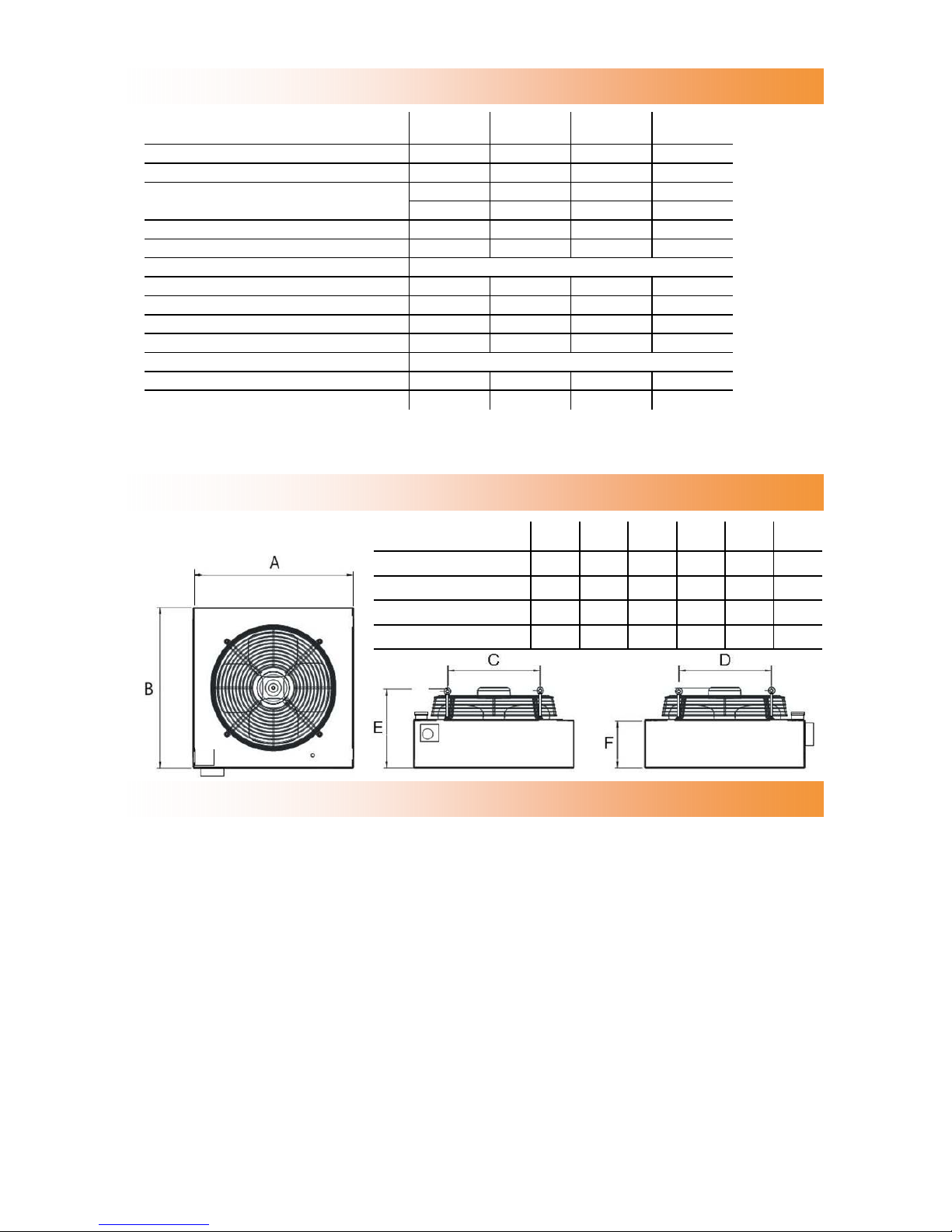
Dimensions.
Model A B C D E F
DS4-3 573 573 365 365 357 192
DS10-3 724 724 440 440 368 192
DS3-3 474 474 332 332 318 192
DS6-3 573 573 400 400 318 192
DS3-3 DS4-3 DS6-3 DS10-3
Mounting Height m 4 - 8 6 - 12 10 - 18 10 - 18
Approx Mounting Centres ¹ m 13 - 16 15 - 20 16 - 21 17 - 23
Air Volume m³/h
3000 5300 6600 9000
c.f.m
1765 3199 3885 5297
Maximum Throw m 8 12 18 18
Velocity m/s 3.77 4.72 6.53 5.73
Electrical Supply
230V 50Hz 1Pha
Motor Size W 108 250 380 520
Operating Current A 0.52 1.15 1.75 2.40
Starting Current A 1.5 2.4 6.0 6.7
Fuse Rating A 6 6 6 10
Thermostatic Control
Included
Net Weight kg 15 19 21 27
Sound Pressure Level ² Lp db (A) 44 54 57 59
Notes: ¹ Mounting centres based on mounting height. (i.e. the lower the unit, the further they are apart.) 2 Sound level
r=5m,Q=1,A=160m²

The information contained in this technical bulletin is designed to aid a qualified or competent
service technician in the instruction it is intended
The destratification fan is equipped with four
suspension points, one on each corner. These
take the form of an eyebolt.
Using either chain or wire rope, connect each
point to a rigid construction i.e. Unistrut, girders
etc.
Ensure the framework is adequate to take
the weight of the particular destratification
unit. Once the destratification fan is in position,
the wiring can commence.
The destratification fan is despatched in a
cardboard box. Remove component from box.
Adjust all outlet louvres to achieve desired air
distribution and ensure blades are not
resonating.
Turn the power/spur on.
The destratification fan will now operate and
automatically switch off when the set
temperature has been reached.
To check operation of the DS type unit, rotate
room stat dial to min setting - fan should
operate. Rotate room stat dial to max setting the fan should turn off. Finally turn the room stat
to approximately 2° to 3° above the desired
room temperature. If the fan does not operate in
this order, check wiring details in fig.2.
The unit is now ready for operation.
Step by step instructions.
CAUTION — HEAVY ITEM!
The following tools and equipment will be
required to complete this task:
1. Lengths of chain or suspension wire,
accessories, and relevant tools.
2. Length of 3 core 1.0mm² cable.
3. Wire strippers/cutters.
4. Electrical screwdriver.
5. Multi-meter.
Fig.1 - Thermostat
for.
Tools required.

Wiring details.
Fig.4 - Typical schematic wiring destrat fans
NORTEK GLOBAL HVAC (UK) LTD
Fens Pool Avenue
Brierley Hill
West Midlands DY5 1QA, U.K.
tel 01384 489250
Fax 01384 489707
reznorsales@nortek.com
www.reznor.co.uk
 Loading...