

Page 1
HAZARD INTENSITY LEVELS
g
p
1. DANGER: Failure to comply will result in severe
personal injury or death and/or property damage.
2. WARNING: Failure to comply could result in severe
personal injury or death and/or property damage.
3. CAUTION: Failure to comply could result in minor
personal injury and/or property damage.
Optional Hanger Kits
Option Installation Form RZ-NA I-OPT-HK
(Version A.1)
Obsoletes Form I-OPT-HK Version A
APPLIES TO: Hanger Kit Options CK3,
CK7, CK8, CK9, CK10, CK19
Description/Application/Table of Contents
Description, parts listing, and illustrated instructions are provided for each hanger kit. These kits are designed
only for the models and applications described below. See the referenced heater installation manual for clear-
ances (top, sides, bottom, front, and rear), suspension dimensions, and weights. Suspension of the heater is the
responsibility of the installer.
Option
Kit
CK3
CK7
CK8
CK9
CK10
CK19
Description
Swivel Connections
for 1" Pipe for 4-pt
Suspension
4-pt Suspension
Conversion
Swivel Connections
for 2" pipe for 2-pt
Suspension
4-pt Suspension
Conversion Plus
Swivel Connections
Swivel Connectors
for 1" Pipe for 4-pt
Suspension
Alternate Sus
Points providing
nearly equal loading
at four points
ension
Use with
Models
(H)EEDU Duct
Furnace
F To add two hanger brackets for changing
UDAP; UDAS; F To adapt a unit with 2-pt suspension so
F To add two han
LDAP Packaged
Heaters; UDAP;
UDAS; UDBP;
UDBS; B; OH;
OB; RA; RAD;
and F with
optional 4-pt
suspension
B Suitable for units equipped with isolation
To adapt the duct furnace so that it may be
suspended from threaded 1" stationary
pipes.
from standard 2-pt suspension to 4-pt
suspension.
that it may also be suspended from two
threaded stationar
standard 2-pt suspension to 4-pt
suspension and adapt the unit so that it
may be suspended from four threaded 1"
stationary pipes.
To adapt a unit with 4-pt suspension so
that it may be suspended from four
threaded 1" stationary pipes.
vibration suspension and or seismic protectio n with lo nger than 10" rod hangers.
Option CK19 changes the suspension
points and suspension dimensions.
Application Page
y pipes.
er brackets to change from
Reference Heater Installation Manual
by Model
2 EEDU and HEEDU - Form RZ-NA I-
EEDU
2-3 F - Form RZ-NA I-F/B
3-4 UDAP and UDAS - Form RZ-NA I-
UDA
F - Form RZ-NA I-F/B
4 F - Form RZ-NA I-F/B
5-6 LDAP - Form RZ-NA I-LDAP
UDAP and UDAS - Form RZ-NA IUDA
UDBP and UDBS - Form RZ-NA IUDB
B and F - Form RZ-NA I-F/B
OH and OB - Form RZ-NA I-OH/OB
RA and RAD - Form RZ-NA IRA/RAD 140/235
RA and RAD - Form RZ-NA IRA/RAD 350/500
7-8 B - Form RZ-NA I-F/B
Other Ce iling Bracket for Unit Heaters - Option CK22 is available for small sizes of Models UDAP and UDAS.
Hanger See Supplemental Installation Form RZ-NA I-UD-CS.
Kits Infrared Models - Options CK11-CK18 are not included in this form. Options CK11-CK18 are hanging chain and
turnbuckle kits for tubular infrared heaters. For parts lists and instructions for hanger and turnbuckle kits, see Supplemental Installation Form RZ-NA I-VR-HK and/or RZ-NA I-VR/TRP/TR-TK. Hanging chain for infrared high intensity
heaters is Option UE1 or UE2. See Heater Installation Manual, Form RZ-NA I-RIH.
WARNING: The instructions in this sheet are written for adding new suspension points or
preparing a heater for suspension prior to installation. If your heater is installed, for your
safety, turn o the gas and the electric before adding or changing suspension. Follow the
instructions on the heater to restart. Check for proper operation.
Form I-OPT-HK (Version A.1), Mfg #98346 (Rev 4), Page 1
Page 2
Option Kits and Instructions
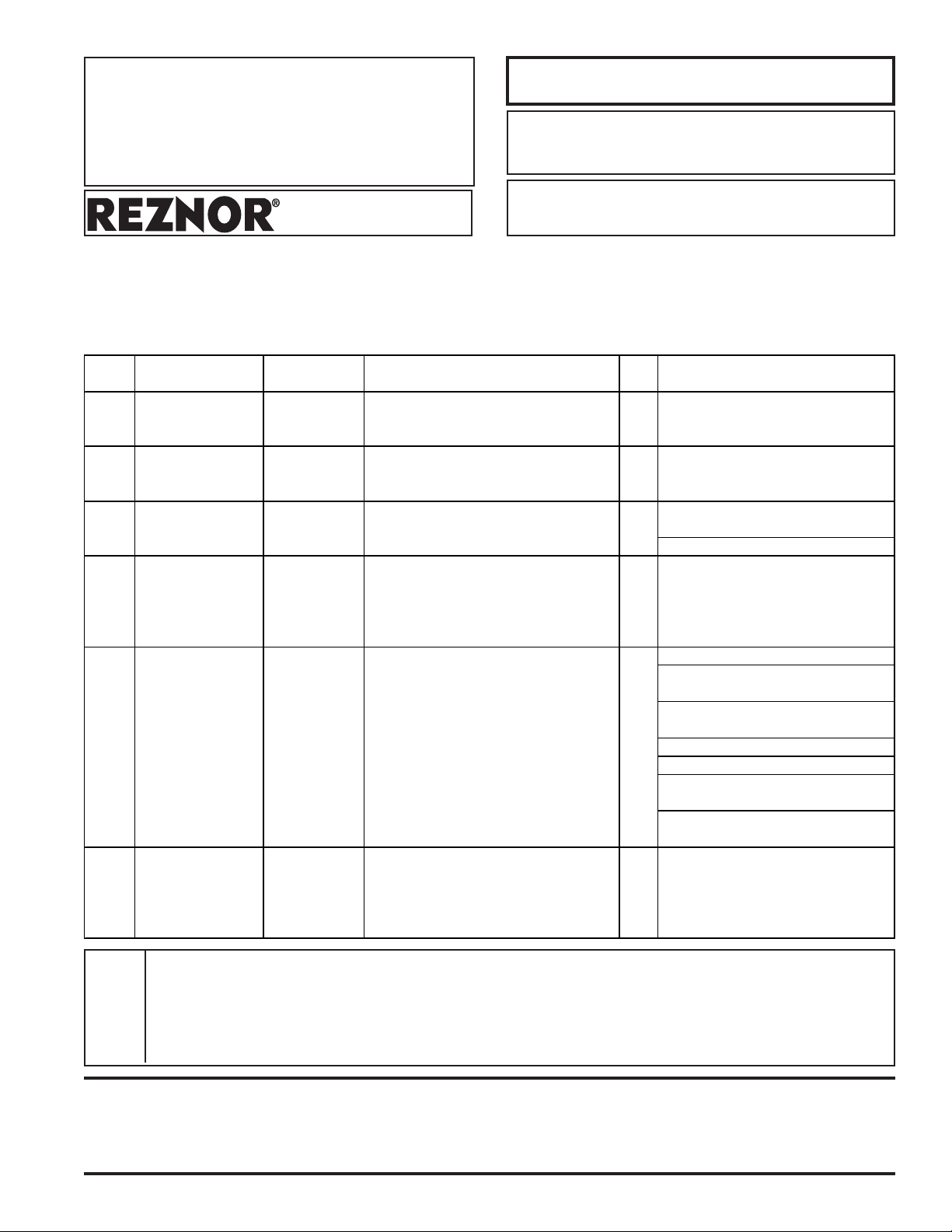
OPTION CK3 Swivel Connectors
for Model Series
EEDU
CAUTION: Check to be
sure that all swivels turn
freely.
OPTION CK7 4-Point
Suspension for
Models F
This option is designed to add swivel connections to a Model (H)EEDU duct
furnace to suspend a single furnace from four 1" threaded stationary pipes.
Option CK3 (Package P/N 57959) includes:
Qty Description P/N
4 Swivel Connector Assy 9557
FIGURE 1
This option is designed to convert a Model F with standard 2-point suspension
to 4-point suspension.
Instructions
1. Remove lockwasher and nut
from swivel connector.
2. Put bolt down through hole in the
hanger bracket.
3. Attach securely with lockwasher
and nut.
4. Repeat on all hanger brackets.
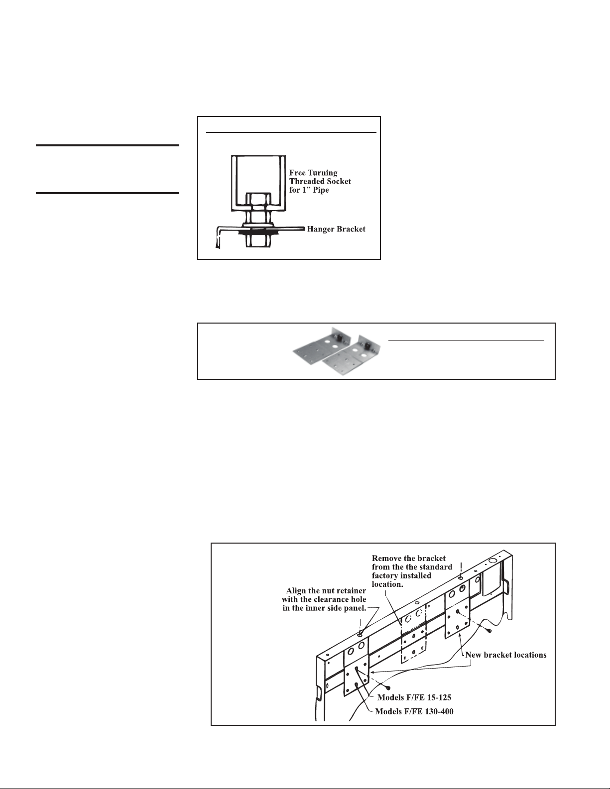
Option CK7 (Package P/N 98508) includes:
FIGURE 2A
- Hanger Kit
Option CK7
Qty Description P/N
2 Hanger Bracket 96386
Assembly
(NOTE: Also applies to
obsolete Model FE.)
Installation Instructions for Option CK7
Tools Required - 5/16" Nut Driver
1. Remove the heater from the carton.
Remove the wooden crate bottom from the bottom of the heater.
Remove one of the heater outer side panels.
2. Remove the Factory-Installed Hanger Bracket Assembly
Remove the two screws that are holding the factory-installed hanger bracket
assembly to the heater. Re-insert the two screws (without the hanger bracket)
into the same holes in the heater inner side panel.
3. Determine the new locations for the two hanger bracket assemblies (one from
the kit and the one removed in Step 2). See FIGURE 2B.
FIGURE 2B - New
Bracket Locations
4. Install Hanger Bracket Assemblies - Remove the screw from the inner side
panel at one of the new locations. Position one of the hanger bracket assemblies
Form I-OPT-HK (Version A.1), Mfg #98346 (Rev 4), Page 2
Page 3
so that the nut retainer is aligned with the clearance hole in the top of the side
panel. Insert the screw removed from the side panel through the center slotted
hole in the hanger bracket. Adjust the bracket so that it is tight against the top of
the heater. Tighten screw securely.
Following the same procedure, attach the other hanger bracket assembly at
the second location. Replace the outer side panel.
5. Remove the outer side panel from the opposite side and repeat Steps 2-4 on that
side.
6. Installation of the 4-point suspension hanger kit is complete. Since the crate bot-
tom has been removed, protect the bottom of the heater with plywood or other
appropriate material. If the bottom is not supported, the bottom access panel
could be damaged.
Follow the instructions in the heater installation manual to complete the
installation of your heater.
OPTION CK8 2-Pt Suspension
with Swivel
Connectors Models UDAP,
UDAS, and F
(NOTE: Model F instructions
also apply to obsolete Model
FE.)
CAUTION: Check to be
sure that all swivels turn
freely.
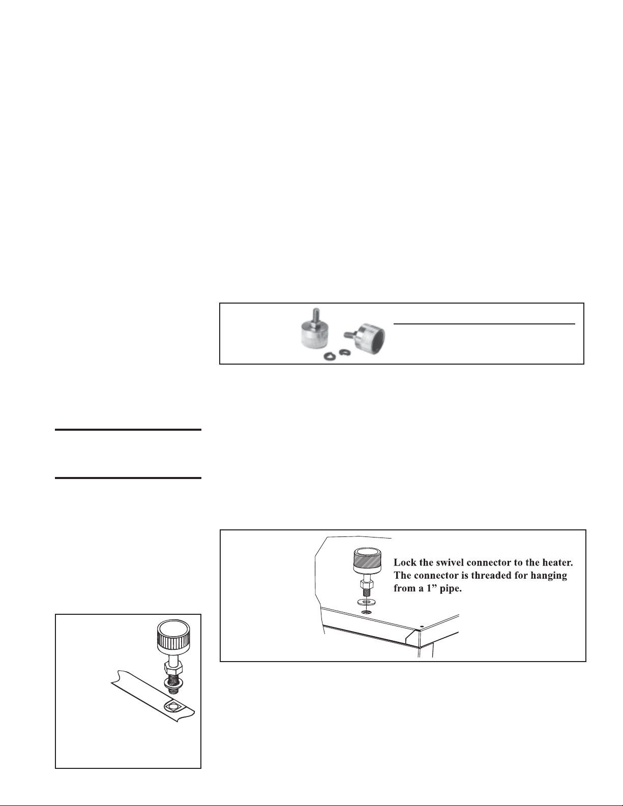
The purpose of this option is to adapt a Model F heater with standard 2-point
suspension so that it can be suspended using two 1", threaded stationary pipes.
Option CK8 (Package P/N 98509) includes:
FIGURE 3A Hanger Kit,
Option CK8
Qty Description P/N
2 Swivel Connector Assy 17627
2 3/8" Lockwasher 5197
Installation Instructions for Option CK8
Tools Required - 9/16" Open-End Wrench
Models UDAP and UDAS (FIGURE 3B)
1. Locate the threaded suspension holes in the top of the heater cabinet that are
used for 2-pt suspension (center holes).
2. Place a lockwasher over each hole.
3. Screw the swivel hanger connector assembly into the heater's cage nut retainer.
(The lockwasher must be between the top panel and the swivel hanger connector assembly.) Tighten firmly.
NOTE: If installing a Model UDAS, be certain that the unused suspension holes on
the control side are plugged. Follow the heater installation instructions.
FIGURE 3B Model UDAP
or UDAS
FIGURE 3C
- Model F
Do NOT
capture
outer panel; it must be
removable for future
service.
Model F (FIGURES 3C & 3D)
1. Locate the two hanger bracket holes in the top of the heater cabinet.
2. Place a lockwasher over the hole, being careful not to catch the cutout portion of
the painted side panel. The outer panel must remain removable for future service. See FIGURE 3C.
3. Screw the swivel hanger connector assembly into the hanger bracket. (The
lockwasher must be between the inner heater side panel and the swivel hanger
connector assembly). Tighten firmly. See FIGURE 3D.
Form I-OPT-HK (Version A.1), Mfg #98346 (Rev 4), Page 3
Page 4

Hanger Option Kits and Instructions (cont'd)
OPTION CK8 2-Point
Suspension with
Swivel Connectors
-Models UDAP,
UDAS, and F
(cont'd)
OPTION CK9 4-Point
Suspension with
Swivel Connectors
- Models F only
(NOTE: Also applies to
obsolete Model FE)
FIGURE 3D - 2-Point
Suspension with Swivel
Connectors - Model F
Models UDAP, UDAS, and F
4. Repeat Steps 2 and 3 at the other suspension point.
5. Installation of the 2-point swivel connection kit is complete. Follow the instruc-
tions in the heater installation manual to complete installation of the heater.
This option is designed to convert a Model F with standard 2-point suspension
to 4-point suspension with swivel connectors.
Option CK9 (Package P/N 98510) includes:
Qty Description P/N
2 Hanger Bracket Assembly 98386
4 Swivel Connector Assembly 17627
4 3/8" Lockwasher 5197
CAUTION: Check to be
sure that all swivels turn
freely.
FIGURE 4A - Swivel 4-pt
Hanger Kit, Option CK9
Installation Instructions for Option CK9
Tools Required - 9/16" Open-End Wrench; 5/16" Nut Driver
1. Convert to 4-point Suspension - Refer to instructions for Option CK7 on
pages 2-3. Follow Steps 1 through 5 to convert the heater to 4-point suspension.
2. Install Swivel Connectors - Refer to instructions for Option CK8 on page 3.
Follow Model F Steps 1 through 3 to install the swivel connection. Attach a
swivel at each suspension point. See FIGURE 4B.
3. Installation of the 4-point suspension kit with swivel connections is complete.
Since the crate bottom has been removed, protect the bottom of the heater with
plywood or other appropriate material. If the bottom is not supported, the bottom
access panel could be damaged.
Follow the instructions in the heater installation manual to complete the installation of your heater.
FIGURE 4b - 4-Point Suspension
with Swivel Connectors - Model F
Form I-OPT-HK (Version A.1), Mfg #98346 (Rev 4), Page 4
Page 5

OPTION CK10 4-Point
Suspension with
Swivel Connectors
(Models LDAP;
UDAP, UDAS;
UDBP, UDBS; F, B;
OH, OB, RA, RAD See paragraph for
specific
applications)
(NOTE: Model F kits also
apply to obsolete Model FE.
Model B kits also apply to
obsolete Model BE.)
CAUTION: Check to be
sure that all swivels turn
freely.
This option is designed to add swivel connectors to a Model F unit heater that
is already equipped with optional 4-point suspension or to a Model LDAP,
UDAP, UDAS, UDBP, UDBS, B, OH, OB, RA or RAD heater that is standardly
equipped with 4-point suspension. The four swivel connections allow the heater
to be suspended from four 1", threaded stationary pipes.
Option CK10 (Package P/N 98511) Swivels for 3/8"
hanger rods/brackets includes:
Qty Description P/N
4 Swivel Connector Assy 17627
8 3/8" Lockwasher 5197
4 3/8" Hex Nuts 1438
FIGURE 5A - Swivel Hanger Kit,
P/N 98511, for 3/8" Hanger Brackets
Applications: All sizes of Models UDAP/UDAS ; all sizes of Models UDBP/
UDBS ; all sizes of Models F/B ; all sizes of Models OH/OB manufactured
prior to 10/94; and Models RA/RAD 110/140/235 manufactured prior to 10/
94.
Option CK10 (Package P/N 134477) Swivels for 1/2"
hanger rods/brackets includes:
Qty Description P/N
4 Swivel Connector Assy 134476
4 1/2" Lockwasher 45549
Installation
Instructions for
Option CK10
FIGURE 5B - Swivel Hanger Kit,
P/N 134477 for 1/2" Hanger Brackets
Applications: All sizes of Models OH/OB/RA/RAD manufactured beginning
10/94 (NOTE: Models RA/RAD 350 manufactured prior to 10/94 have 7/16"
hanger brackets. A swivel hanger kit is not available for RA/RAD 350 with
7/16" hanger brackets.)
Option CK10 (Package P/N 207938) Swivels for 1/2"
hanger rods/brackets includes:
Qty Description P/N
4 Swivel Connector Assy 207939
4 1/2" Lockwasher 45549
FIGURE 5C - Swivel Hanger Kit,
P/N 207938, for 1/2" Hanger Brackets
Applications: All sizes of Model LDAP .
Select the instructions for the unit being installed.
Models UDAS, UDAP, F, B - Follow the same instructions as for Option CK8,
pages 3-4. Repeat the process at all four hanger bracket locations. (NOTE: The
four nuts and four of the washers in the kit will not be used.)
(UDAS NOTE: Be sure that any unused suspension holes on the control side
are plugged; see heater installation instructions. )
Models UDBP, UDBS - The suspension points on the hanger bar on the top of
Model UDBP and UDBS heaters are not threaded. At each hole, place a
lockwasher, insert the swivel through the lockwasher and the hanger bar. Fas-
Form I-OPT-HK (Version A.1), Mfg #98346 (Rev 4), Page 5
Page 6

Option Kits and Instructions (cont'd)
Installation
Instructions for
Option CK10
(cont'd) -- Select
instructions that
apply to Model.
IMPORTANT: Be sure the
threaded swivel connectors
are locked to the hanger bar
as illustrated.
FIGURE 5D - Suspension
of a Model OH/OB/RA/
RAD with Optional
Swivel Connectors
(Option CK10) from 1"
threaded pipe
ten securely with a lockwasher and nut. See FIGURE 5C . Repeat the proce-
dure at each suspension point.
FIGURE 5C - Installing Swivel Connections on Model UDBP
and UDBS
Models OH, OB, RA, RAD - Four eld-
supplied 3/8" or 1/2" at washers are required.
1. Place a flat washer at the threaded
suspension point as illustrated in FIG-
URE 5D.
2. Put a lockwasher on the swivel assem-
bly and screw the swivel connector into
the suspension point. Tighten firmly.
3. Repeat the procedure at the other three
suspension points.
Installation of the four swivel connectors
is complete. Follow the instructions in the
heater installation manual to complete the
installation.
FIGURE 5E Suspension of a Model
LDAP with Optional
Swivel Connectors
(Option CK10) from
1" threaded pipe
"U"-shape
tting
Strut attached to
the top of the
heater
Form I-OPT-HK (Version A.1), Mfg #98346 (Rev 4), Page 6
Swivel
Assembly
Hex Nut
Lockwasher
Spring Nut
Model LDAP
1. Put a lockwasher on the swivel assem-
bly and screw the swivel connector into
the suspension point on the "U" fitting.
Tighten firmly.
2. Repeat the procedure at the other three
suspension points. Be sure the threaded
swivel connectors are locked to the
heater as illustrated.
Installation of the four swivel connectors
is complete. Follow the instructions in the
heater installation manual to complete the
installation.
Page 7

OPTION CK19 Alternative 4-Pt
Suspension Points
for Model B Blower
Units
(NOTE: Also applies to
obsolete Model BE.)
FIGURE 6B - Suspension
Dimensions for Model B Heater
with Hanger Kit Option CK19
This option is designed so that each suspension point carries a nearly equal
load. NOTE: Suspension point dimensions change; see FIGURE 6B.
Option CK19 (Package P/N 165742) includes:
N/PnoitpircseDytQ
1 Right Side Hanger Bar 162829
1 Left Side Hanger Bar 162830
4 HHD Tap Bolts 3/8-16NCX 1-1/2, #5 114350
8 3/8" Lockwasher 5197
FIGURE 6A - Hanger Kit for
Blower Model B, Option CK19
Size
25-50
75
100
125
165
200
250-300
400
A B
inches mm inches mm
11-7/8 302 9-1/8 232
13-7/8 352 11-1/8 283
15-7/8 403 13-1/8 333
21-5/8 549 18-7/8 479
18-5/8 473 15-7/8 403
21-5/8 549 18-7/8 479
27-1/8 689 24-3/8 619
35-3/8 899 32-5/8 829
Form I-OPT-HK (Version A.1), Mfg #98346 (Rev 4), Page 7
Page 8

OPTION CK19 Alternative 4-Pt
Suspension
Points for Model B
Blower Units
(cont'd)
Installation Instructions for Option CK19
Tools Required - 9/16" Open-End Wrench
1. Locate the four hanger bracket holes in the top of the heater cabinet (two on
each side).
2. On the side of the heater where the electrical supply connects, carefully place
two lockwashers over each hanger bracket hole. From the kit, select the hanger
bar with the wider flange and the cutout hole in the center. Position the hanger
bar along the top edge of the heater on top of the washers. (Two washers are
required between the heater and the hanger bar to allow for removal of the side
panel.). Attach the hanger bar with two of the bolts, securing them to the hanger
bracket weld nut. See FIGURE 6C.
3. Attach the left side hanger bar the same way using the remaining four washers
and two bolts.
4. The heater is ready for suspension from 3/8" threaded hanger rods. Use field-
supplied hardware to attach the hanger rods as illustrated in FIGURE 6D.
FIGURE 6C - Attach a
Hanger Bar along the Top
Edge on Each Side of the
Heater (bars extend out
over the blower)
View of hanger bar hardware with heater side panel removed
(for illustration only; do not remove side panel to install)
Sequence:
Bolt
Hanger Bar
2 Washers
Heater Top Panel
Hanger Bracket Nut (behind the heater side
panel; do not remove side panel)
Two washers (from the kit) are required between
the hanger bar and the heater to provide clearance
for removing the heater side panel for service.
FIGURE 6D - Use
threaded hanger
rods to suspend the
heater from the
hanger bar
suspension points
(hardware and
rods are eld
supplied)
REZNOR
Form I-OPT-HK (Version A.1), Mfg #98346 (Rev 4), Page 8
www.ReznorHVAC.com; (800) 695-1901
© 2014 Reznor LLC, All rights reserved. Printed in the U.S.A.
MANUFACTURER OF HEATING, COOLING, AND VENTILATING SYSTEMS
Trademark Note: Reznor
10/14 Form RZ-NA I-OPT-HK (Version A.1)
®
is registered in at least the United States.
 Loading...