

Form CP-CAUA-GC (01-18)
Obsoletes CP-CAUA-GC (04-15)
Gas Conversion Kits and Instructions
Applies to: Model CAUA
General and Warnings
FOR YOUR SAFETY
— WHAT TO DO IF YOU
SMELL GAS
• Do not try to light any
appliance.
• Do not touch any
electrical switch; do not
use any phone in your
building.
• Leave the building
immediately.
• Immediately call your
gas supplier from a
phone remote from the
building. Follow the gas
supplier’s instructions.
• If you cannot reach your
gas supplier, call the
re department.
— Installation and service
must be performed by
a qualied installer,
service agency, or the
gas supplier.
DANGER:
The conversion kit is to be selected and installed by a qualied
service person in accordance with these instructions and
in compliance with all codes and requirements of authorities
having jurisdiction. Failure to follow instructions could result
in death, serious injury and/or property damage. The qualied
agency performing this work assumes responsibility for this
conversion.
In Canada, gas conversion shall be carried out in accordance with the
requirements of the Provincial Authorities having jurisdiction and in
accordance with the requirements of CSA-B149.1 and .2 installation
code.
WARNING
Improper installation, adjustment, alteration, service, or
maintenance can cause property damage, injury, or death.
Read the installation, operation, and maintenance instructions
thoroughly before installing or servicing this equipment.
FOR YOUR SAFETY: Do not store or use gasoline or other
ammable vapors and liquids in the vicinity of this or any
other appliance.
HAZARD INTENSITY LEVELS used in this manual.
1. DANGER: Failure to comply will result in severe personal injury or
death and/or property damage.
2. WARNING: Failure to comply could result in severe personal
injury or death and/or property damage.
3. CAUTION: Failure to comply could result in minor personal injury
and/or property damage.
DANGER:
The gas burner in this gas-red equipment is designed and equipped to provide safe, complete
combustion. However, if the installation does not permit the burner to receive the proper supply of
combustion air, complete combustion may not occur. The result is incomplete combustion which
produces carbon monoxide, a poisonous gas that can cause death.
DANGER
Safe operation of indirect-red gas burning equipment requires a properly operating vent system
which vents all ue products to the outside atmosphere. FAILURE TO PROVIDE PROPER VENTING
WILL RESULT IN A HEALTH HAZARD WHICH COULD CAUSE SERIOUS PERSONAL INJURY OR
DEATH.
If installed as a separated-combustion system, install either the horizontal or vertical combustion
air/vent system illustrated in the heater installation manual, using the concentric adapter supplied.
All installations must comply with the combustion air requirements in the installation codes and
instructions. Units installed in a conned space must be supplied with air for combustion and
ventilation as required by Code and in the heater installation manual. Combustion air at the burner
should be regulated only by manufacturer-provided equipment. NEVER RESTRICT OR OTHERWISE
ALTER THE SUPPLY OF COMBUSTION AIR TO ANY HEATER. MAINTAIN THE VENT SYSTEM IN
PROPERLY OPERATING CONDITION.
Form CP-CAUA-GC, P/N 170635R9, Page 1
Description and
Kit Selection
NOTE: When converting
a unit with a twostage valve (Option
AG2), check for valve
manufacturer. If the unit
has a two-stage WhiteRodgers valve, a new
two-stage gas valve is
required. See page 8 for
details.
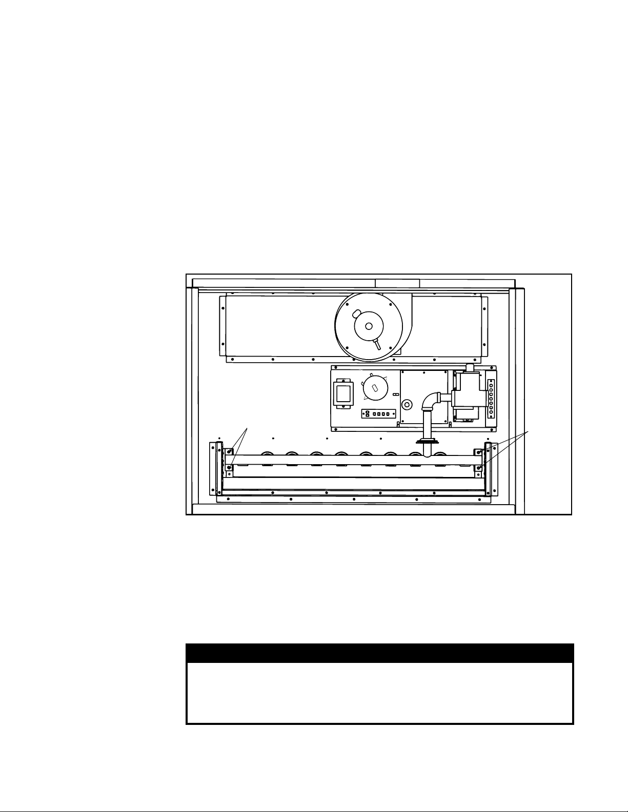
FIGURE 1 - View of
Model CAUA Control
Compartment with
Access Panel and
All Sections of
the Burner Cover
Removed
(Wires are not illustrated.)
The gas conversion kits in these instructions are for Model CAUA heaters equipped
with specic single-stage or two-stage valves (see NOTE left). The kits are for operation at sea level. See pages 5-6 for conversion kit application and components. See
page 7 for high altitude burner orices.
In order to verify which conversion kit is compatible to your heater, it is necessary to
know the type of valve that is on the heater. From the rating plate, copy the complete
Model of the heater. Also, copy the manufacturer's name and number found on the
gas valve.
IMPORTANT: Match the actual Model No. of the valve to the one listed for that kit.
If the actual Model No. is different from the one listed, contact your manufacturer
Representative to select and verify parts required for gas conversion.
Gas Conversion
1. Check kit contents to the parts list. (Parts lists are on pages 5-6.)
Instructions
2. Turn off the gas supply at a shutoff valve upstream of the combination gas valve
3. Install the Regulator Spring Kit
The manufacturer of the regulator spring kit and the gas valve
MUST be the same. Spring kits of different manufacturers are not
interchangeable, and each spring kit MUST be used only in the
Form CP-CAUA-GC, P/N 170635R9, Page 2
valve for which the kit is designated.
The conversion kits include two or three regulator spring kits -- one or two for a singlestage valve and one for a two-stage valve. Check the package carefully and choose
the regulator spring kit that corresponds with the valve on the heater. NOTE: The other
regulator spring kit(s) will not be used.
The kits listed in this manual are intended for use on units that will be operated at
sea level. Conversion of a unit using these kits will not alter the input rate. Refer to
the rating plate on the heater for input rate and other appropriate information.
and turn off the electrical supply. Open the control access panel.
WARNING
To install a regulator spring conversion kit, follow the valve manufacturer's
installation instructions that are included with the regulator spring kit. After a new
spring kit is installed, it is necessary to adjust the spring for the correct manifold
pressure. This adjustment can only be made after the heater is in operation.
Instructions are in Step No. 7.
4. Install Burner Orices
WARNING
Do not attempt to drill orices. Use factory-supplied orices only.
NOTES: Kits that apply to various sizes of heaters include the quantity of burner ori-
ces required for the largest size of heater. When converting the smaller sizes, there
will be extra burner orices which will not be used. Burner orices in these kits apply to
sea level operation only. For high altitude, see Burner Orice Chart, page 7.
1) Remove all burner cover sections. Depending on when the unit was
manufactured, there will be either two or three sections. If two, there will be
a right and a left section which extend over the front. If three, there will be a
right, a left, and a separate front section.
2) Disconnect the manifold from the valve.
3) Remove the screws that retain the manifold assembly. (See FIGURE 1.)
4) With the manifold assembly removed from the heater, unscrew all of the
existing orices and replace with the orices included in the conversion kit.
5. Re-Assemble the Heater
Reverse the procedure in Step 4 to re-assemble the heater.
Be certain that the manifold is positioned properly in relationship to the burner rack.
Attach the conversion disk to the heater near the gas valve.
6. Check for Gas Leaks
Use a commercial leak detecting uid or a rich soap and water solution. Leaks are
indicated by the presence of bubbles.
a) Turn on the gas shutoff valve upstream of the combination gas valve. Check for
gas leaks between the gas shutoff valve and the combination gas valve. If a leak
is detected, tighten the connection and recheck. When there are no leaks, turn the
manual shutoff valve off.
b) Turn on the electrical supply. Turn on the gas and follow the instructions on
the heater to relight the burner. Check all manifold connections for leaks. If a leak
cannot be stopped by tightening, turn off the gas and the electric, and replace the
part or parts until there are no leaks.
7. Measure the Manifold Pressure
Before attempting to measure or adjust the manifold gas pressure, be certain that
the inlet (supply) pressure is within the specied range (see pressure requirements
in tables below) for the gas being used both when the heater is in operation and
on standby. Incorrect inlet pressure could cause excessive manifold gas pressure
immediately or at some future time.
Follow these requirements and the instructions to measure and, if needed, adjust
the manifold gas pressure:
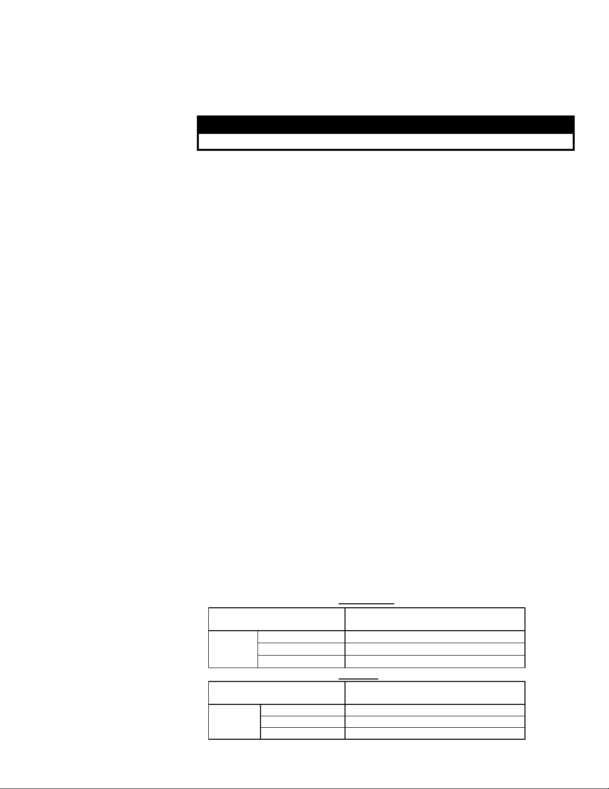
Pressure Requirements for Natural Gas
Inlet (Supply)Pressure
Manifold
Pressure
Pressure Requirements for Propane
Inlet (Supply) Pressure
Manifold
Pressure
Single stage 3.5" w.c.
2-stage high re 3.5" w.c.
2-stage low re 1.8" w.c.
Single Stage 10" w.c.
2-stage high re 10" w.c.
2-stage low re 5" w.c.
5" w.c. minimum (or as stated on the
rating plate); 14" w.c. maximum
11" w.c. minimum (or as stated on the
rating plate);14" w.c. maximum
Form CP-CAUA-GC, P/N 170635R9, Page 3
 Loading...