

Page 1
W ARNING: All components of the gas supply system
Installation Instructions for
must be leak tested prior to placing equipment into
service. Never test for leaks with an open flame.
Failure to comply could result in severe personal
Carryover Lighter Tube - Natural or
Propane Connection
injury or death. Use an approved leak-test solution
or soap solution to detect leaks.
®
Parts/Installation Form RZ-NA-P-X/XE-LTR-TUBE
Obsoletes RGM 704 (Version A)
APPLIES TO: Model Series X, RX, XE, RXE, REB
Description/Application
These carryover kits are intended for installation on Model (H) (C) RX; (H) (C) X; (H) (C) RXE; (H) (C) REB, and (H) (C) XE that did not include
factory-installed lighter tube carryovers (units manufactured prior to 11/86).
Parts List (Lighter Tube Carryover Kits are listed by Size of Heater)
Size 75/100 125 150/175 200/225 250/300 350 400
For NATURAL GAS Furnace - Kit P/N 92135 92136 92137 92138 92139 92140 92141
Drip
Shield
Lighter
Tube
Regulated
Carryover
Assembly for
Propane Gas
Components:
Lighter Tube Assembly 9899 9859 9821 9783 9747 9711 9520
Length (inches) 12-3/8 15-1/8 20-5/8 26-1/8 34-3/8 39-7/8 45-3/8
Drip Shield 15015 15014 15013 15012 15011 15010 14957
Carryover Orifice 9870 9870 9680 10370 10370 9792 9792
Drill Size 70 70 65 59 59 54 54
Aluminum Tube 93389 93389 93389 93389 93389 93389 93389
Brass Elbow 93388 93388 93388 93388 93388 93388 93388
Compression Fitting 9664 9664 9664 9664 9664 9664 9664
1/2" lg, #10 Sheetmetal Screw 11813 11813 11813 11813 11813 11813 11813
Quantity 6666666
For PROPANE GAS Furnace - Kit P/N 92142 92143 92144 92145 92146 92147 92148
Components:
Regulated Carryover Assembly 100712 100712 100712 100712 100712 100712 100712
Lighter Tube Assembly 9899 9859 9821 9783 9747 9711 9520
Length (inches) 12-3/8 15-1/8 20-5/8 26-1/8 34-3/8 39-7/8 45-3/8
Drip Shield 15015 15014 15013 15012 15011 15010 14957
Carryover Orifice 9870 9870 9680 9680 10370 9791 9791
Drill Size 70 70 65 65 59 56 56
1/2" lg, #10 Sheetmetal Screw 11813 11813 11813 11813 11813 11813 11813
Quantity 6666666
Installation Instructions
1. Turn off the gas supply upstream of
the valve and turn off the electric.
2. Mark the wires connected to the gas
valve and disconnect.
3. Disconnect spark lead and flame sen-
sor from the ignition controller.
4. Remove the burner rack.
a) Remove the heater side panel.
b) Uncouple the union in the gas supply to
c) Remove the sheetmetal screws in the top
CAUTION: Hold burner rack firmly and pull slowly.
5. Follow the illustrated instructions on
pages 1-4 to install the Lighter Tube
permit removal of the burner rack.
corners of the burner rack and pull the
burner rack out of the unit.
Carryover Kit. Test for leaks. When the
installation is complete, reverse Installation Instruction Nos. 1-4 to re-
assemble the heater. Test for proper
and safe operation.
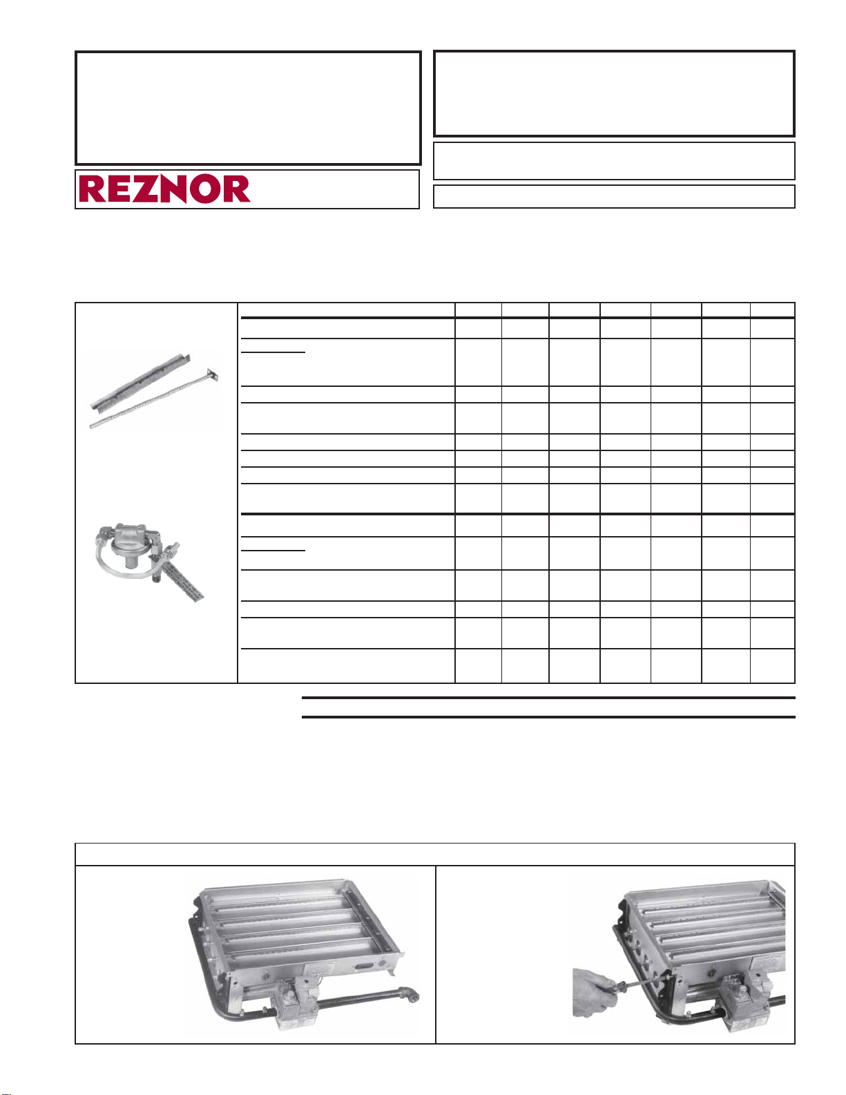
INSTALL LIGHTER TUBE - Steps 1-6 apply both natural gas and propane gas heaters.
1. Burner rack
without
lighter tube.
2. Back off screws that
attach the manifold
to the burner rack.
Remove top screws.
Form RZ-NA-P-X/XE-LTR-TUBE, Mfg #101147, Page 1
Page 2
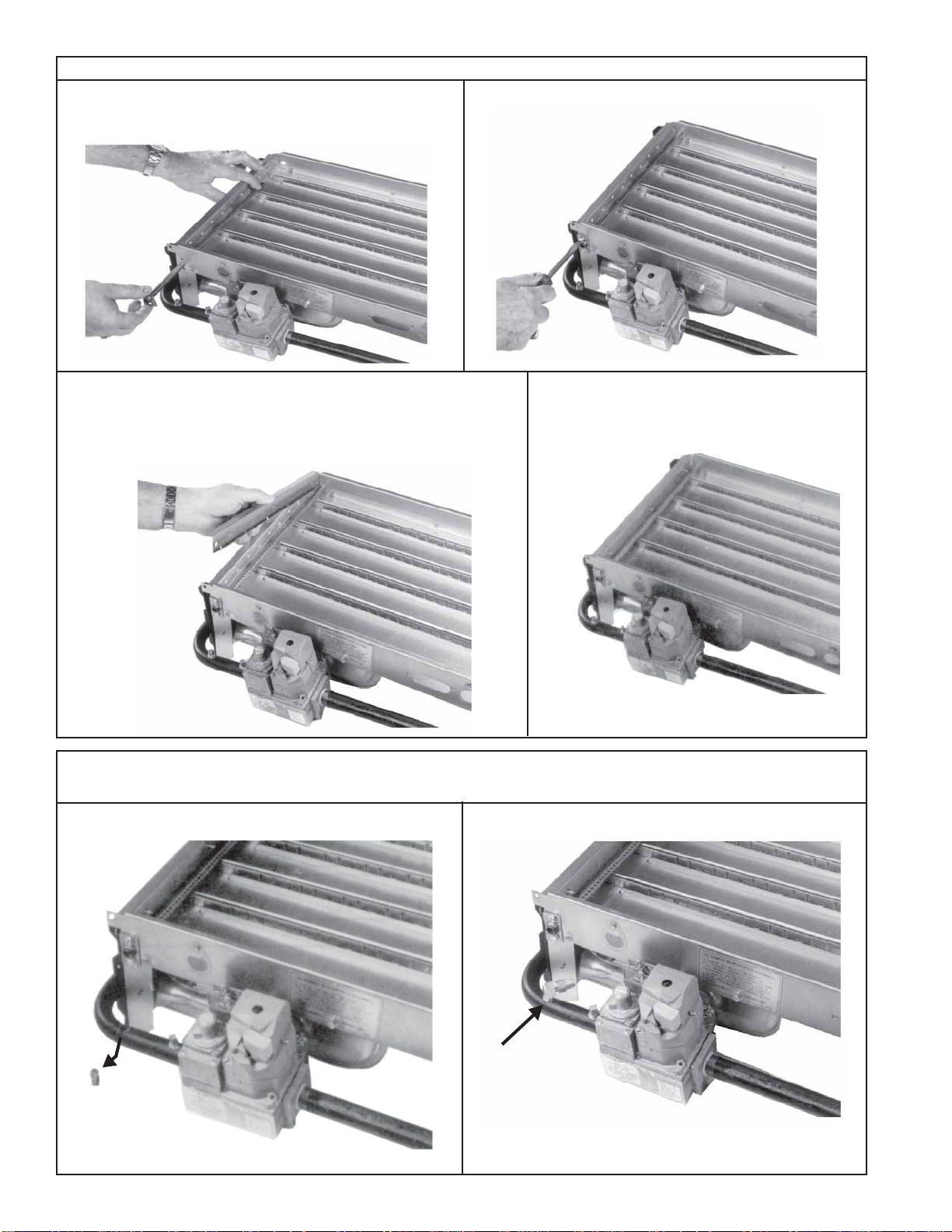
INSTALL LIGHTER TUBE (cont'd) - Steps 1-6 apply both natural and propane gas heaters.
3. Slide lighter tube into the holes provided. Ensure pin
holes in the tube are facing outward toward the
burner tubes.
5. Install drip shield. NOTE: "Z" effect when observed from the
side. Compress lighter tube into half circle cutouts in the burner
tubes. Be sure the tube is seated. The 90o angle on the drip
shield should be against the top and side of the burner rear
plate.
4. Using two screws, secure the lighter tube to the
burner rack.
6. Install the drip shield screws to secure the
drip shield. Reverse Step No. 2 on page 1.
INSTALL LIGHTER TUBE GAS CONNECTIONS - Steps 7-11 apply to Natural Gas Units
ONLY
7. Remove the pipe plug from the manifold.
Form RZ-NA-P-X/XE-LTR-TUBE, Page 2
8. Install the 90° elbow and position as illustrated.
Page 3

9. Install correct carryover orifice and brass compression fitting. See Step 10.
11. Install tubing and tighten. Leak test prior to placing
unit into operation.
10. Insert the carryover orifice into the lighter tube. If
fit is tight, lightly tap the orifice into position.
WARNING: All components of gas
supply system must be leak tested prior
to placing equipment into service.
Never test for leaks with an open flame.
Failure to comply could result in severe
personal injury or death. Use an
approved leak-test solution or soap
solution to detect leaks.
INSTALL LIGHTER TUBE GAS CONNECTIONS - Steps 12-19 apply to Propane Gas Units
ONLY
12. Remove the pipe plug from the manifold.
If the unit has a lighter tube with natural gas and is
being converted to propane gas, remove the 90°
elbow, the tubing, and the lighter tube orifice.
13. Install the straight brass fitting in the manifold.
Form RZ-NA-P-X/XE-LTR-TUBE, Mfg #101147, Page 3
Page 4

INSTALL LIGHTER TUBE GAS CONNECTIONS (cont'd) - Step s 12-19 apply to Propane Gas
Units ONLY
14. Install 1/4" tubing into straight brass fitting and
tighten.
16. Install the regulator with the
90o elbows already installed
and position as shown. Be sure
gas flow is in the direction of
the arrow on the regulator.
Slide the nut and ferrule on the
90o elbow over the tubing and
tighten in place.
Verify that the gas flow is in
the direction of the arrow on
the regulator and that the
regulator gas pressure is set for
1.0" w.c. on propane gas.
15. Place tag on tubing.
17. Install correct carryover orifice
and brass compression fitting. See
Step 18.
18. If fit is tight, lightly tap orifice into position. 19. Install tubing between orifice and regulator. Leak
test all fittings prior to placing into operation.
WARNING: All components of gas supply system must be leak tested prior to placing
equipment into service. Never test for leaks with an open flame. Failur e to comply could
result in severe personal injury or death. Use an approved leak-test solution or soap
solution to detect leaks.
Form RZ-NA-P-X/XE-LTR-TUBE, Page 4
800-695-1901 www.RezSpec.com
©2044 5H]QRU//& All rights reserved. Printed in U.S.A.
MANUFACTURER OF GAS, OIL, ELECTRIC HEATING AND VENTILATING SYSTEMS
Trademark Note: Reznor
04 OG POD Form P-X/XE-LTR-TUBE9HUVLRQ
®
is registered in the United States and other countries.
 Loading...