

Reznor 12, 20, LCSA-4 Series, 30, 50 Installation Commissioning Servicing & User Instructions
...
1610LCSA-4--EN
Gas-Fired, Balanced-Flue or
Power-Vented Unit Heater
LCSA-4
Installation, commissioning, servicing & user instructions
These appliances meet the following EC Directives
DIR 2009/142/EC: GAD
DIR 2004/108/EC: EMC
DIR 2006/95/EC: LVD
DIR 2006/42/EC MD
Applies to
Austria, Belarus, Bulgaria, China, Czech Republic, Croatia, Cyprus, Denmark, England, Estonia, Finland,
Germany, Greece, Hungary, Iceland, Latvia, Lithuania, Montenegro, New Zealand, Norway, Poland, Romania,
Russian Federation, Serbia, Slovakia, Slovenia, South Africa, Spain, Sweden, Turkey, Ukraine
WARNING
Improper installation, adjustment, alteration, service or maintenance can cause property
damage, injury, or death. All work must be carried out by appropriately qualified persons.
The manufacturer does not take any responsibility in the event of non-observance of the
regulations concerning the connection of the apparatus causing a dangerous operation of the
apparatus, possibly resulting in damage to the apparatus and/or environment in which the unit
is installed.
Please read this document carefully before commencing installation commissioning and/or
servicing.
Leave it with the user or attached to the appliance or gas service meter after installation.
Subject to modifications
1/25

TABLE OF CONTENTS
1.0 INTRODUCTION
1.1 Basic Information
1.2 Warranty
2.0 TECHNICAL DATA
2.1 Specifications
2.2 Dimensions
3.0 GENERAL REQUIREMENTS
3.1 Related Documents
3.2 Heater Location
3.3 Combustion Air Inlet Pipe and Flue Pipe
3.4 Air Supply
3.5 Air Distribution System
3.6 Electrical Supply
3.7 Gas Supply
4.0 INSTALLATION
4.1 Uncrating and Preparation
4.2 Suspending the Heater
4.3 Fitting the Combustion Air Inlet/Flue Pipe System
4.3.1 Fitting the Flue Pipe
4.3.2 Fitting the Combustion Air Socket Guard - Type B Installation
4.3.3 Fitting the Combustion Air Pipe - Type C Installation
4.4 Gas Connection
4.5 Electrical Connections
4.6 Room Thermostat Siting
5.0 AIR DISTRIBUTION
6.0 COMMISSIONING AND TESTING
6.1 Electrical Check
6.2 Gas Connection
6.3 Suspension and Support
6.4 Lighting the Heater
6.4.1 To Turn the Heater ON
6.4.2 To Turn the Heater OFF for Short Periods
6.4.3 To Turn the Heater OFF for Long Periods
6.5 Heater pipe work
6.6 Adjustments
6.7 Air Distribution System
6.8 Heater Controls
6.9 Handing Over
7.0 SERVICING INSTRUCTIONS
8.0 REMOVAL AND REPLACEMENT OF PARTS
8.1 Main Burner Removal
8.2 Main Burner Injectors
8.3 Ignition System
8.4 Operating Gas Valve
8.5 Limit Controls
8.6 Combustion Air Pressure Switch
8.7 Combustion Air Fan
9.0 FAULT FINDING
10.0 PARTS LIST
11.0 GAS CONVERSION
12.0 USERS INSTRUCTIONS
13.0 HEALTH & SAFETY STATEMENT
2/25
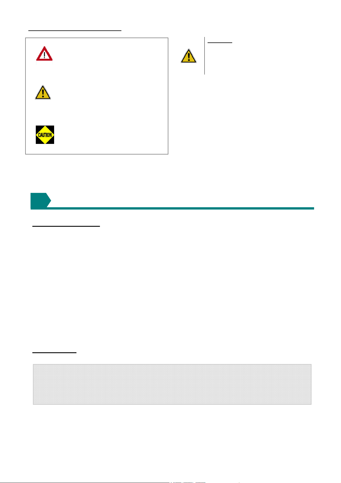
HAZARD INTENSITY LEVELS
DANGER
danger
WARNING
CAUTION
Failure to comply will result in
severe personal injury or
death and/or property
damage.
Failure to comply could result
in severe personal injury or
death and/or property damage
Failure to comply could result
in minor personal injury and/or
property damage.
INTRODUCTION
1
WARNING: The electrical isolator should
only be used in an emergency and should
not be used for closing down the main
burner, as it switches off the fan
prematurely and may damage the heat
exchanger, invalidating the warranty.
Attention :
This appliance is not intended for use by
persons (including children) with reduced
sensory or mental capacities, or lack of
experience and knowledge, unless they have
been given supervision or instruction
concerning use of the appliance by a person
responsible for their safety.
Children should be supervised to ensure that
they do not play with the appliance.
1.1 Basic Information
The instructions in this manual apply to Model LCSA4 gas-fired/fan-assisted warm air heaters. These
models have an axial fan for air delivery. These
heaters are designed for overhead suspension and
are suitable for indoor installation only installed at an
operation ambient temperature between -15°C and
45°C. When installed as a type C12/C32 and where
the height above floor level is greater than 1.8
meters measured to the underside of the appliance
they may be used as a garage air heater. This
appliance must be installed in accordance with the
rules in force. Before installation, check that the
local distribution conditions, nature of gas and
pressure and adjustment of the appliance are
compatible.
A permanent electricity supply of 230 volts, 50 Hz,
single phase is required.
Heaters are approved for:
Type C
Type C
Type B
When the external control calls for heat, an
electronic control begins the ignition sequence to
provide for a safe start. About 30 seconds after the
call for heat, the fan will begin circulating warm air.
The electronic control will supervise the flame during
the entire heating cycle to ensure safe operation.
When the required room temperature is reached, the
main burner will shut down leaving the fan running to
cool down the heat exchanger. After approximately
45 seconds, the fan delay relay will turn off the fan.
- horizontal vent for balanced-flue heaters;
12
- vertical vent for balanced-flue heaters;
32
- vertical vent;
22
1.2 Warranty : Warranty is void if:
a) LCSA-4 heaters are installed in atmospheres containing flammable vapors or atmospheres
containing chlorinated or halogenated hydrocarbons or atmospheres containing any silicone,
aluminum oxide, etc., that adheres to spark ignition flame sensing probes.
b) The installation is not in accordance with these instructions.
c) Axial fan-type unit heater is connected to a duct system or fitted with a non-authorized air
distribution device.
3/25
2
TECHNICAL DATA
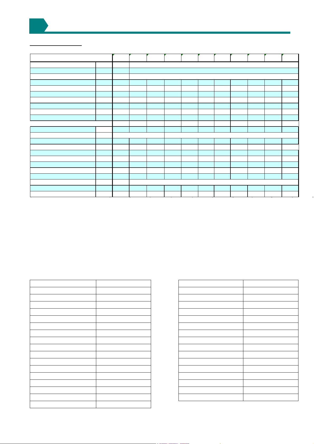
2.1 Specifications
Table 1a
LCSA-4 12 20 30 35 45 50 60 75 100 120 145
Gas category
Comb. Air & Flue, type B
Comb. Air & Flue, type C
(1)
(1)
Connection c ollars mm 80 100 100 130 130 130 130 130 130 130 130
Heat input Hs kW 13,33 26,42 31,63 43,95 54,38 61,08 73,25 87,85 114,87 144,81 165,47
Heat input Hi kW 12,00 23,80 28,50 39,60 49,00 55,00 66,00 79,15 103,50 130,40 149,00
Heat output kW 11,14 21,82 25,99 36,23 44,64 50, 77 60,92 73,13 94,50 119,32 137,39
Thermal Efficiency % 93,00 92,00 91,00 92,00 91,00 92,00 92,00 92,00 91,00 92,00 92,00
Gas c onsumption G20
Gas c onsumption G31
Gas cons um ption Lw (20mb ar)
Gas cons um ptio n Ls (13m bar)
Gas pipe connection
Real temperature rise
Air flow measured
(2)
(3)
(3)
m³/h 1,27 2,52 3,02 4,19 5,19 5,82 6,98 8, 38 10,95 13,80 15,77
kg/h NA 1,86 2,22 3,09 3,82 4,29 5,15 6,17 8,24 10,17 11,62
m³/h NA 3,07 3,68 5,11 6,32 7,10 NA 10,22 NA NA NA
(*)
m³/h NA 3,50 4,19 5,82 7,20 8,08 NA 11,63 NA NA NA
(*)
1/2"
K 30 31 33 33 313034 29 29 32 35
m³/h 1100 2000 2300 3200 4300 5000 5200 7300 8000 10800 11400
Nominal motor speed RPM 1381 1256 1333 1300 1310 928 1346 1344 935 872 875
Recommended mounting height
Horizontal t hrow
Sound Press ure
Sound Press ure
(5)
(6)
(7)
m2,5
m9,5
dB(A) 36
dB(A) 43
3 4 44455566
13 17 24 25 27 30 32 31 38 39
42 37 46 45 45 47 48 52 54 56
49 44 53 52 52 54 55 59 61 63
(4)
Elec trical service (protec tion IP20)
Total elec trical rating W 530
Weight kg 59
(*) : only fo r Polan d
(1) Gas A ppliance Class ific atio ns fo r Aprro ved Venting M ethods based o n CEN-repo rt CR1749:2001
(2) There is a difference between the gas co nnect io n diameter and the diamet er o f the supply line. Always use t he mo st adequate diam eter o f the supply
line to minimize the pressure dro p through the gas pipes - if necessary, reduce the diameter o f the supply line at the inlet o f the unit.
(3) Figure fo r iso therm al co nditions.
(4) Height f ro m flo or t o bo tto m surf ace of heater. These are recomm andatio ns o nly. Po sitio ning of unit heaters f o r proper perf ormance is applicat ion dependent.
Care sho uld be taken to avo id mount ing the heaters abo ve t hese reco mm endatio ns, unless downturn nozzle opt io ns are used, as significant stratification may
occur resulting in poo r floo r co verage and higher energy los ses thro ugh the ro of s tructure.
(5) Isot hermal co nditio ns at 20°C ambient air t emperature, discharge lo uvre zero def lectio n, v = 0,5 m/s. The air thro w will be influenced by the height o f t he
building, mounting height o f the unit, ambient temperature & adjustment o f t he louvres.
(6) Sound pressure level in dB(A) in free field co nditions , measured at 5 metres from the unit
(7) Sound pressure level in dB(A), measured at 5 m etres fro m the unit with A =160m² and Q=2
360 250 370 370 540 760 760 850 1730 1730
59 64 94 99 114 114 126 184 242 279
Table 1b : Gas categories
Country Gas category Country Gas category
Austria II2H3P Montenegro II2H3+
Belarus II2H3+ New Zealand II2H3+
Bulgaria I2H or I3P Norway II2H3 B/P
China II2H3+ Poland II2E3P
Czech republic II2H3+ Portugal II2H3+
Croatia II2H3P Romania II2H3 B/P
Cyprus II2H3+ Russian Federation I2H or I3P
Denmark II2H3 B/P Serbia II2H3+
England II2H3+ Slovakia II2H3+
Estonia II2H3+ Slovenia II2H3+
Finland II2H3 B/P South Africa II2H3+
Germany I2ELL Spain II2H3+
Greece II2H3+ Sweden II2H3 B/P
Hungary II2HS3P Turkey II2H3+
Iceland II2H3+ Ukraine I2H or I3P
Latvia II2H3+
Lithuania II2H3+
4/25
see table 1B
B22P
C12, C42, C62
3/4"
230/240V 1N ~ 50Hz
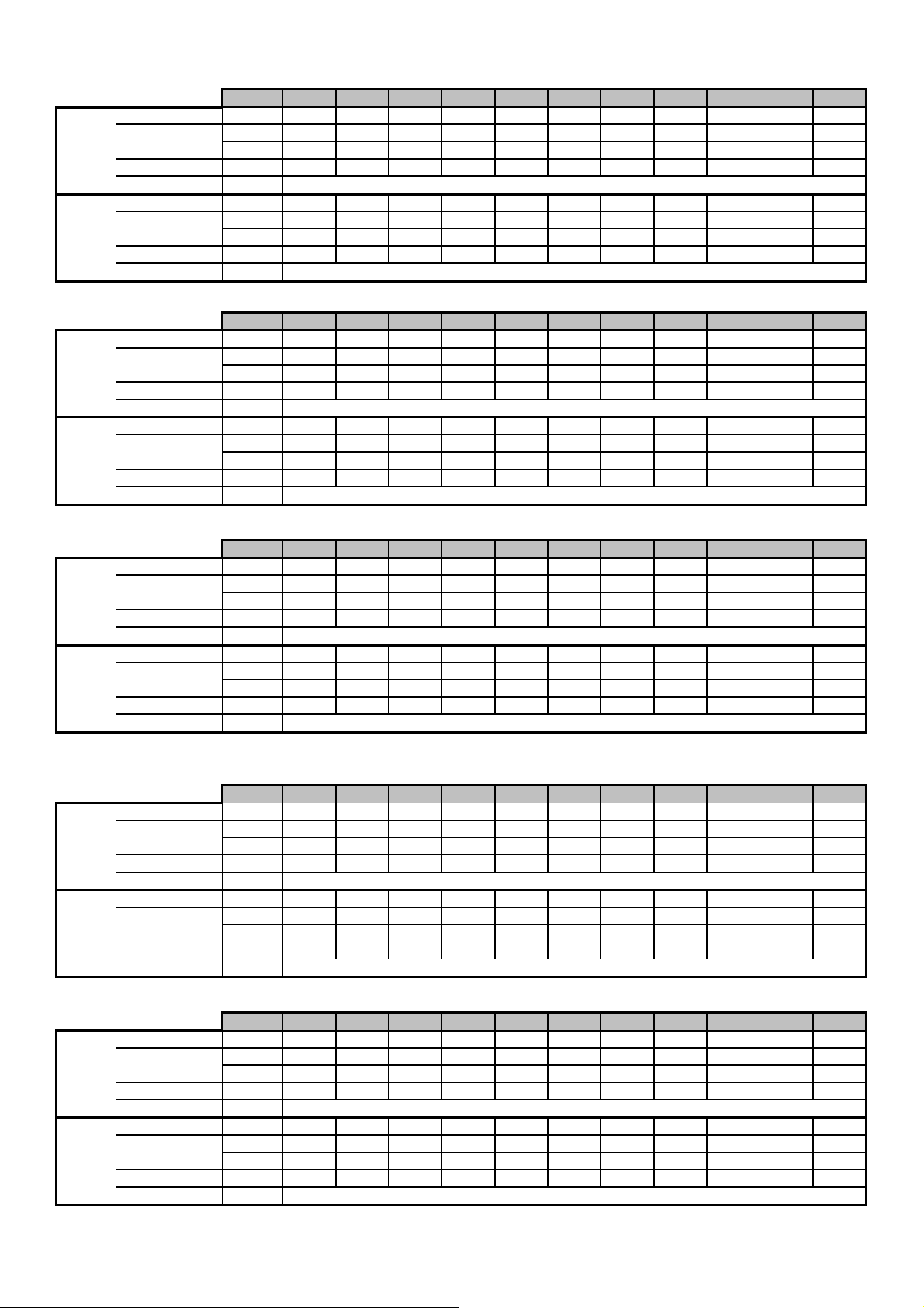
Table 2 :Injector size and burner pressures
Belarus, China, Croatia, Czech Republic, Cyprus, England, Estonia, Greece, Iceland, Latvia, Lithuania, Montenegro, New Zealand, Portugal, Serbia, Slovenia,
Slovakia, South Africa, Spain , Turkey, Poland
LCSA-4
Injector quantity 5 5 6 8 10 8 8 10 12 10 12
Injector size
G20
Burner pressure (1) mbar 8,10 8,00 7,25 7,10 6,90 9,20 8,50 8,30 7,50 9,20 9,00
Nat. Gas
Inlet pressure mbar
Injector quantity - 5 6 8 10 8 8 10 12 10 12
Injector size
G31
Burner pressure (1) mbar - 35,80 35,80 36,20 35,90 30,10 35,60 35,40 34,40 30,70 30,60
Prop. Gas
Inlet pressure mbar
Special poland
LCSA-4
Injector quantity - 5 6 8 10 8 - 10 - - -
Injector size
G27
Burner pressure (1) mbar - 8,30 8,20 8,35 8,25 11,40 - 9,25 - - -
Inlet pressure mbar
Injector quantity - 5 6 8 10 8 - 10 - - -
Injector size
G2,350
Burner pressure (1) mbar - 8,25 8,45 9,55
Inlet pressure mbar
Model1220303545506075100120145
mm 1,50 2,10 2,10 2,20 2,20 2,40 2,70 2,70 2,90 3,40 3,40
marking 150 210 210 220 220 240 270 270 290 340 340
20
mm - 1,15 1,15 1,15 1,15 1,40 1,45 1,45 1,50 1,95 1,90
marking - 115 115 115 115 140 145 145 150 195 190
37
Model1220303545506075100120145
mm - 2,40 2,40 2,40 2,40 2,60 - 3,00 - - -
marking - 240 240 240 240 260 - 300 - - -
20
mm - 2,60 2,60 2,50
marking - 260 260 250
2,60 3,40
260 340
8,40 6,00
13
-
3,90
-
390
-
5,25
---
---
---
Austria, Germany, Hungary, Russian Federation, Ukraine
LCSA-4
Injector quantity 5** 5 6 8 10 8 8 10 12 10 12
Injector size
G20
Burner pressure (1) mbar 8,10 8,00 7,25 7,10 6,90 9,20 8,50 8,30 7,50 9,20 9,00
Nat. Gas
Inlet pressure mbar
Injector quantity - 5 6 8 10 8 8 10 12 10 12
Injector size
G31
Burner pressure (1) mbar - 35,80 35,80 36,20 35,90 30,10 35,60 35,40 34,40 30,70 30,60
Prop. Gas
Inlet pressure mbar
(* ): Inlet pressure for Hungary = 25mbar
(**): no nat gas for Germany
Bulgaria, Denmark, Finland, Norway, Sweden
LCSA-4
Injector quantity 5 5 6 8 10 8 8 10 12 10 12
Injector size
G20
Burner pressure (1) mbar 8,10 8,00 7,25 7,10 6,90 9,20 8,50 8,30 7,50 9,20 9,00
Nat. Gas
Inlet pressure mbar
Injector quantity - 5 6 8 10 8 8 10 12 10 12
Injector size
G31
Burner pressure (1) mbar - 28,06 28,06 28,37 28,14 23,59 27,90 27,75 26,96 24,10 24,00
Prop. Gas
Inlet pressure mbar
Model1220303545506075100120145
mm 1,50 2,10 2,10 2,20 2,20 2,40 2,70 2,70 2,90 3,40 3,40
marking 150 210 210 220 220 240 270 270 290 340 340
mm - 1,15 1,15 1,15 1,15 1,40 1,45 1,45 1,50 1,95 1,90
marking - 115 115 115 115 140 145 145 150 195 190
Model1220303545506075100120145
mm 1,50 2,10 2,10 2,20 2,20 2,40 2,70 2,70 2,90 3,40 3,40
marking 150 210 210 220 220 240 270 270 290 340 340
mm - 1,15 1,15 1,15 1,15 1,40 1,45 1,45 1,50 1,95 1,90
marking - 115 115 115 115 140 145 145 150 195 190
20(*)
50
20
30
Romania
LCSA-4
Injector quantity 5 5 6 8 10 8 8 10 12 10 12
Injector size
G20
Burner pressure (1) mbar 8,10 8,00 7,25 7,10 6,90 9,20 8,50 8,30 7,50 9,20 9,00
Nat. Gas
Inlet pressure mbar
Injector quantity - 5 6 8 10 8 8 10 12 10 12
Injector size
G31
Burner pressure (1) mbar - 28,60 28,80 29,20 28,80 28,10 28,50 28,40 27,70 26,40 25,30
Prop. Gas
Inlet pressure mbar
(1) : with open service door
Model1220303545506075100120145
mm 1,50 2,10 2,10 2,20 2,20 2,40 2,70 2,70 2,90 3,40 3,40
marking 150 210 210 220 220 240 270 270 290 340 340
20
mm - 1,20 1,20 1,20 1,20 1,45 1,50 1,50 1,60 1,95 1,90
marking - 120 120 120 120 145 150 150 160 195 190
30
5/25
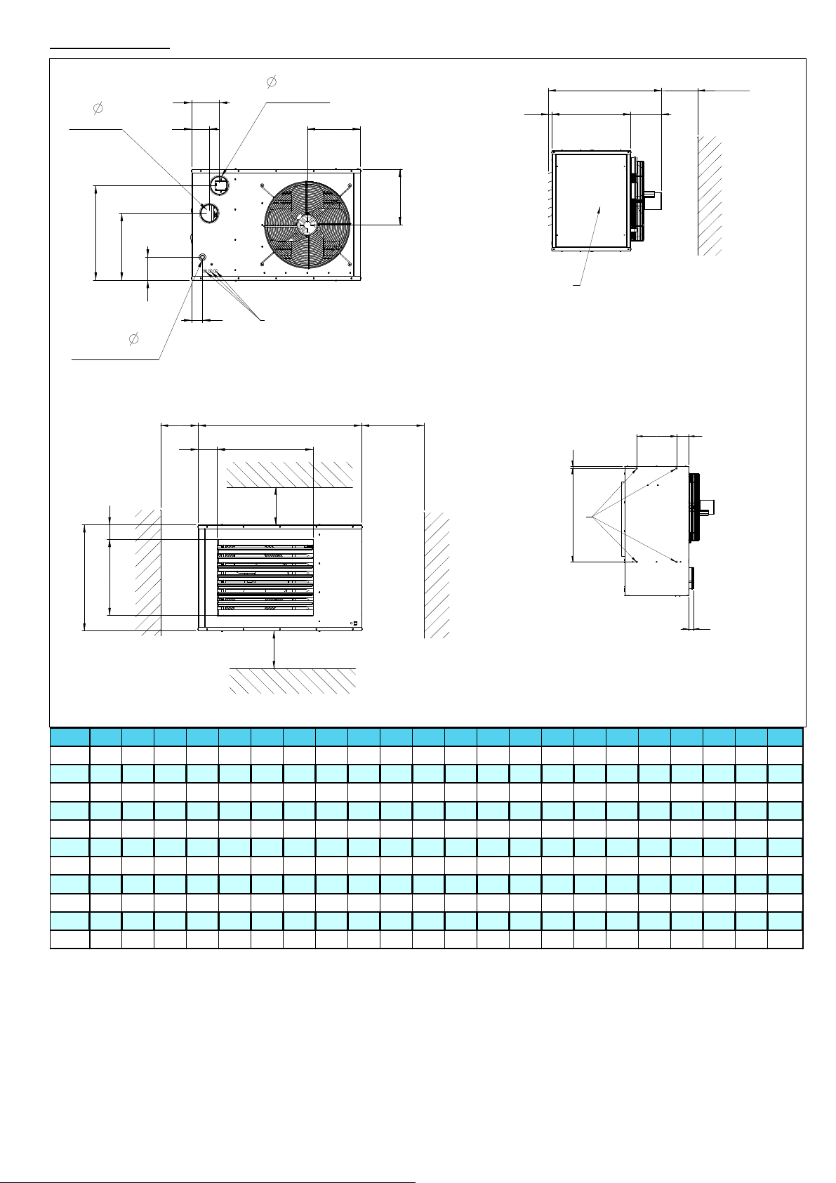
2.2 Dimensions
D
Flue Inlet
Q
P
N
W
Gas Connection
S
R
150
E
D
J
250 min
Flue Outlet
30
C
I
K
L
2
M
1
A
F
500 min
V
19
T
GH
150
3
U
B
51
150
LCSA-4 A B C D E F G H I J K L M N P Q R S T U V W
12 965 567 652 80 71 531 130 305 100 782 334 280 87 106 345 444 122 221 123 611 406 1/2"G
20 965 567 652 100 71 531 130 305 103 785 334 280 87 106 345 444 122 221 123 611 406 1/2"G
30 965 567 652 100 74 531 94 370 139 821 334 280 87 106 345 444 122 221 123 611 406 1/2"G
35 965 845 652 130 74 531 154 517 138 824 331 420 82 175 508 720 134 211 123 611 406 3/4"G
45 965 845 652 130 74 531 117 605 138 824 331 420 82 175 508 720 134 211 123 611 406 3/4"G
50 1298 845 652 130 151 759 154 517 156 838 409 425 82 175 508 720 135 212 123 942 406 3/4"G
60 1298 845 652 130 151 759 154 517 139 824 409 425 82 175 508 720 135 212 123 942 406 3/4"G
75 1298 845 652 130 151 759 117 605 139 824 409 425 82 175 508 720 135 212 123 942 406 3/4"G
100 1298 954 807 130 151 759 73 808 301 1022 479 477 82 180 608 833 212 212 123 942 550 3/4"G
120 1750 980 846 130 67 1100 164 602 177 1057 348 490 90 175 595 795 160 256 20 1365 770 3/4"G
145 1750 1150 846 130 67 1100 173 692 177 1057 348 570 90 177 736 936 160 256 20 1365 770 3/4"G
1 Electrical connections
2 Service panel
3 Suspension points (M10 female)
6/25
GENERAL REQUIREMENTS
3
3.1 Related documents
It is important that all gas appliances are installed in
accordance with the rules in force and by
appropriately qualified persons. Failure to install
appliances correctly could lead to prosecution. It is
in your own interest and that of safety to ensure
compliance with the law.
3.2 Heater location
The location chosen for the air heater must permit
the provision of a satisfactory flue system venting to
outdoor atmosphere and adequately ventilated to
provide for combustion air. The location must also
provide sufficient space to allow the heater to be
serviced.
Table 3
Minimum installation clearances (mm)
LCSA-4 mm
Top 150
Flue connector 150
Access panel 800
Non access side 150
Bottom 150
Rear* 450
* Measure rear clearance from the back of the motor
Table 4
Recommended mounting heights to underside (m)(*)
LCSA-4 12 20
Mounting
height
* Height from floor to bottom surface of heater. These are
recommendations only. Positioning of heaters depends on
application.
Air heaters should, where ever possible always be
installed to blow toward or along external wall
surfaces. Where two or more air heaters are
installed in the same room, a general scheme to
ensure continuous air circulation should be
maintained for best results.
Suspended heaters are most effective when located
as close to the occupancy zone as possible, this fact
should be born in mind when determining the
mounting heights to be used. Care should be
exercised to avoid directing warm air directly onto
the occupants. Partitions, columns, counters,
storage racking, etc. should be taken into account
when choosing the location so that an unobstructed
path for the air circulation can be maintained.
Where air heaters are located in the centre of the
space to be heated, the air should be discharged
toward outside walls. In large areas, they should be
located to discharge air along outside walls with
additional heaters provided to blow air into the
centre of the area.
In places where infiltration of cold is excessive, such
as entrance doors it is desirable to locate a heater
so that warm air is discharged directly toward the
source of cold air from a distance of 4,5 - 6,0m
2,53456
30→-50 60-→100 120→145
Air heaters should not be installed in
corrosive atmospheres, i.e. near plating
or degreasing plants or in areas where
there is a fire risk.
Do not locate the air heater where it may
be exposed to water spray, rain, etc.
3.3 Combustion air supply & flue
system
The air heater may be installed as a balanced flue
(Type C) heater requiring both a combustion air inlet
duct and a flue pipe or as a power vented (Type B)
heater, which requires only a flue pipe exhausting to
outdoors. All products of combustion must be flued
to outdoor atmosphere.
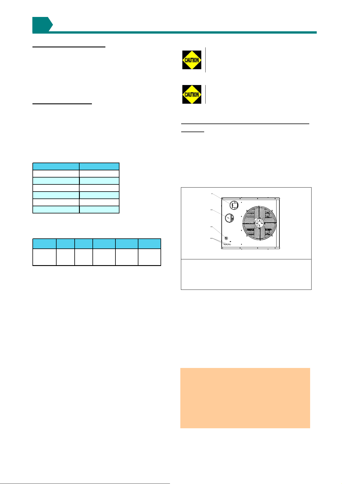
Figure 2a : Combustion air and flue pipe sockets
1
2
3
4
Legend :
1 Flue outlet socket
2 Combustion air inlet opening
3 Gas connection inlet with sealing ring
4 Electrical connections
Each heater installed as a type B appliance must be
fitted with an individual flue pipe and the combustion
air inlet opening must be provided with a protection
grill (ask your distributor for the appropriate
protection grill (IP20) (dia130 = PN 02 25094 ).
Each heater installed as a type C appliance must be
fitted with an individual combustion air/flue pipe
system. Only systems specified by the air heater
manufacturer may be used.
Common flue and combustion air systems must
not be used
IMPORTANT: The flue must be installed in
accordance with national and local regulations.
Failure to provide proper flueing could result in
death, serious injury and/or property damage.
The air heater must be installed with a flue to the
outside of the building. Safe operation of any
power vented gas apparatus requires a properly
operating flue system, correct provision for
combustion air, and regular maintenance and
inspection.
7/25
3.3.1 Flues for power vented installations
(Type B appliances)
If the air heater is to be installed as a type B
appliance, air for combustion will be taken from
within the space where the heater is installed.
Ensure that an adequate air supply for combustion
and ventilation is provided within the building in
accordance with the regulations & rules in force.
Table 5 shows flue pipe sizes and maximum pipe
lengths. The minimum flue length is 0.5 metres.
Table 5 Flue pipe diameters & maximum lengths
LCSA-4
Heater socket &
pipe dia
Maximum straight
length
Equivalent length m
of 45° elbow
Equivalent length
of 90° elbow
mm
m
m
20, 30
12 35->145
100 130
80
9
0.75
1.5
Single wall flue pipes are required. All joints must
be sealed to prevent products of combustion from
leaking into the building. An approved flue terminal
is required.
If the flue passes through a combustible element of
the building it must be enclosed by a sleeve of noncombustible material and separated from the sleeve
by at least a 25 mm air break. The temperature of
any combustible material near to the flue must not
exceed 65°C when the heater is in operation. The
flue must be at least 50 mm away from any
combustible material.
Single wall flue pipe exposed to cold air or run
through unheated areas must be insulated. Where
condensation is unavoidable, provision must be
made for the condensation to flow freely to a point
to which it can be released, i.e. a drain or gully. The
condensation drain from the flue must be
constructed from non-corrodible material not less
than 20 mm diameter. Copper or copper based
alloys must not be used for condensation drains.
3.3.2 Combustion air inlet pipe & flue pipe for
balanced flue installation (Type C appliances)
Balanced flue air heaters are designed to be fitted
with a combustion air inlet pipe that obtains outdoor
air and a flue pipe that exhausts flue products to
outdoors.
Air heaters if fitted with a power venter permitting
either a vertical or horizontal combustion air
inlet/flue pipe system. The heaters must be
installed with a concentric vertical or horizontal
flue/combustion air inlet. The heaters are only
approved for use when installed with the
appropriate approved concentric vent terminal.
See table 6.
Both the flue and combustion air pipes must be sealed.
Use gasket sealed seamless aluminium pipe or
equivalent.
The flue pipe must include a re-sealable test port to
allow good average sampling of the flue gas mixture
for testing, the port must be at least 450 mm away
from the air heater flue connection socket.
Follow any flue pipe manufacturers’ installation
instructions for making joints, including connections to
the air heater, for passing through a building element
and for support requirements. If more than one air
heater is being installed in the same place each heater
must have a separate flue system.
Where condensation is unavoidable, provision must
be made for the condensation to flow freely to a
point to which it can be released, i.e. a drain or
gully. The condensation drain from the flue must be
constructed from non-corrodible material not less
than 20 mm diameter. Copper or copper based
alloys must not be used for condensation drains.
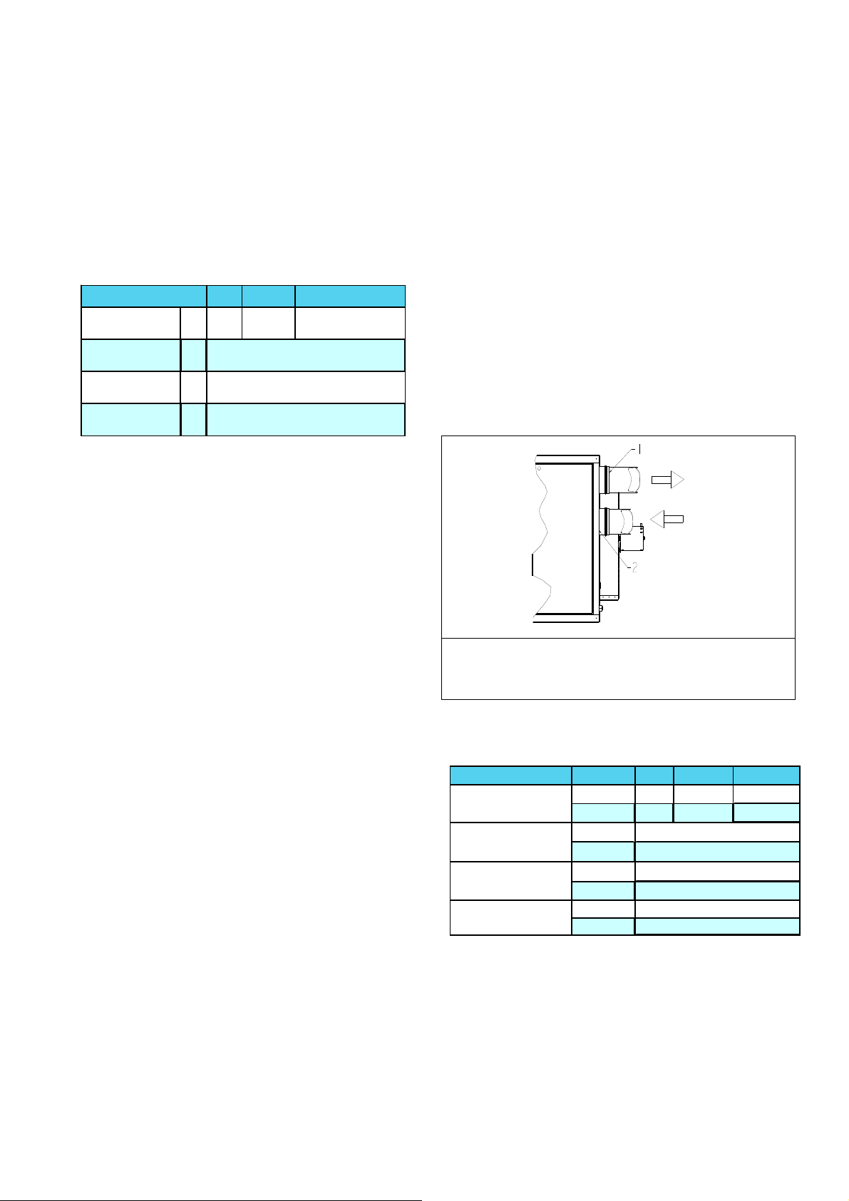
Figure 2b :
Combustion air and flue pipe sockets, Type C
Legend :
1 Flue products flue outlet socket for flue pipe
2 Combustion air inlet opening
Table 6
Combustion air inlet & flue pipe requirements
LCSA-4 12 35 -> 145
Heater socket
& pipe dia
Max. straight
length
Equivalent length
of 45° elbow
Equivalent length
of 90° elbow
Concentric vertical vent or wall terminal : Mugro/Burfix dia 130
Concentric horizontal vent or roof terminal : Mugro/Burfix dia 130
Flue pipe 80 130
mm
Inlet pipe 80 130
Flue pipe
m
Inlet pipe
Flue pipe
m
Inlet pipe
Flue pipe
m
Inlet pipe
20, 30
100
100
9
9
0,75
0,75
1,5
1,5
8/25
 Loading...