

Rexnord Falk Steelflex T10, Falk Steelflex T20 Installation And Maintenance Instructions Manual

This is the Original Document in English Language
Installation and Maintenance Instructions • Falk Steelflex
Type T10 & T20 (Page 1 of 9)
Type T20
®
Type T10
Sizes 1020-1170
Figure 1 - Steelflex T10 & T20 coupling range
Type T10
Sizes 1150-1260
1. General Information
1.1. Falk Steelflex Couplings are designed to provide a mechanical connection between the rotating shafts of mechanical equipment,
using a grid spring to accommodate inherent misalignment while transmitting the power and torque between the connected
shaft.
1.2. These instructions are intended to help you to install and maintain your Falk Steelflex coupling. Please read these instructions prior to
installing the coupling, and prior to maintenance of the coupling and connected equipment. Keep these instructions near the coupling
installation and available for review by maintenance personnel. For special engineered couplings, Rexnord may provide an engineering
drawing containing installation instructions that take precedence over this document.
1.3. Rexnord Industries, LLC owns the copyright of this material. These Installation and Maintenance instructions may not be reproduced in
whole or in part for competitive purposes.
1.4. Symbol descriptions:
Danger of injury to persons.
Damages on the machine possible.
Pointing to important items.
Hints concerning explosion protection.
Rexnord Industries, LLC, 5555 S. Moorland Rd., New Berlin, WI 53151-7953 428-111
Telephone: 262-796-4060 Fax: 262-796-4064 02/2012
e-mail: info@rexnord.com web: www.rexnord.com Supersedes manuals 428-110, 112, 110 - 04/2005

Installation and Maintenance Instructions • Falk Steelflex
®
(Page 2 of 9) Type T10 & T20
2. Safety and Advice Hints
DANGER!
2.1. Safety should be a primary concern in all aspects of coupling installation, operation, and maintenance.
2.2. Do not make contact with the coupling when it is rotating and/or in operation.
2.3. Because of the possible danger to person(s) or property from accidents which may result from improper use or installation of these
products, it is extremely important to follow the proper selection, installation, maintenance and operational procedures.
2.4. All personnel involved in the installation, service, operation, maintenance, and repair of this coupling and the connected equipment
must read, understand, and comply with these Installation and Maintenance instructions.
PRECAUTION!
For this coupling to meet the ATEX requirements, you must precisely follow these installation and maintenance instructions, and the
supplement form 0005-08-49-01. This supplement outlines the ATEX requirements. If the operator does not follow these instructions,
the coupling will immediately be considered non-conforming to ATEX.
2.5. All rotating power transmission products are potentially dangerous and can cause serious injury. They must be properly guarded in
compliance with OSHA, ANSI, ATEX, European machine safety standards and other local standards. It is the responsibility of the user to
provide proper guarding.
2.6. For ATEX requirements the guard must have a minimum of 12.7 mm (1/2 inch) radial clearance to the coupling outside diameter and
allow for proper ventilation.
2.7. Make sure to disengage the electrical power and any other sources of potential energy before you perform work on the coupling.
2.8. Proper lockout-tag out procedures must be followed to safeguard against unintentional starting of the equipment.
2.9. All work on the coupling must be performed when the coupling is at rest with no load.
2.10. Do not start or jog the motor, engine, or drive system without securing the coupling components. If the equipment is started with only
a hub attached, the hub must be properly mounted and ready for operation, with the key and set screw (if included) fastened. When the
full coupling assembly is started, all fasteners and hardware must be completely and properly secured. Do not run the coupling with
loose fasteners.
2.11. The coupling may only be used in accordance with the technical data provided in the Falk Steelflex coupling catalog. Customer
modifications and alterations to the coupling are not permissible.
2.12. All spare parts for service or replacement must originate from or be approved by Rexnord Industries, LLC.
428-111 Rexnord Industries, LLC, 5555 S. Moorland Rd., New Berlin, WI 53151-7953
02/2012 Telephone: 262-796-4060 Fax: 262-796-4064
Supersedes manuals 428-110, 112, 210 - 04/2005 e-mail: info@rexnord.com web: www.rexnord.com

Installation and Maintenance Instructions • Falk Steelflex
Type T10 & T20 (Page 3 of 9)
®
3. Components and Part Numbers
Type T20
Type T10
1020-1140
Type T10
1150-1230
Type T10
1240-1260
Figure 2 - Falk Steelflex Coupling Components
Rexnord Industries, LLC, 5555 S. Moorland Rd., New Berlin, WI 53151-7953 428-111
Telephone: 262-796-4060 Fax: 262-796-4064 02/2012
e-mail: info@rexnord.com web: www.rexnord.com Supersedes manuals 428-110, 112, 110 - 04/2005
Installation and Maintenance Instructions • Falk Steelflex
(Page 4 of 9) Type T10 & T20
®
Description Style Part 1020T 1030T 1040T 1050T 1060T 1070T 1080T 1090T 1100T 1110T 1120T 1130T 1140T
Seal Kit T10 1 & 5 0776650 0776651 0776652 0776653 0776654 0776655 0776708 0776709 0707189 0707190 0707191 0707192 0707193
Seal Kit T20 1 & 5 0706752 0706753 0706754 0706755 0706756 0706757 0706758 0706759 0706760 0706761 0706762 0706763 0706764
Cover Assembly T10 1, 2, 5, 6, 7 0775804 0775805 0775806 0775810 0775811 0775812 0776214 0776215 0776216 0776217 0776218 0776219 0776220
Cover Assembly T20 1, 2, 5, 6, 7 0706739 0706740 0706741 0706742 0706743 0706744 0706745 0706746 0706747 0706748 0706749 0706750 0706751
Hub T10 & T20 3 0246652 0246653 0246654 0246655 0246656 0246657 0246658 0246659 0246660 0246661 0246662 0246663 0246664
Grid T10 & T20 4 0762810 0762811 0762812 0762813 0762814 0758250 0758251 0758252 0758253 0758254 0758255 0758256 0758257
Fastener Set T10 6 0775798 0775798 0775798 0775800 0775800 0775800 0776194 0776194 0776196 0776196 0776221 0776221 0776221
Fastener Set T20 6 0707045 0707046 0707046 0707047 0707047 0707047 0707048 0707048 0707049 0707049 0707050 0707051 0707052
Description Style Part 1150T 1160T 1170T 1180T 1190T 1200T 1210T 1220T 1230T 1240T 1250T 1260T
Seal Kit T10 1 & 5 0725614 0725615 0725616 0725617 0725618 0725619 0725732 0725733 0725734
Seal Kit T20 1 & 5 0725620 0725621 0725622
Cover Assembly T10 1, 2, 5, 6, 7, 8, 9 0767950 0767951 0767952 0767953 0767954 0767955 0427516 0427517 0427518 0422233 0422234 0422235
Cover Assembly T20 1, 2, 5, 6, 7 0706752 0706753 0706754
Hub T10 & T20 3 0333090 0333091 0333092 0333093 0333094 0333095 0334246 0334247 0334248 0334249 0334250 0334251
Grid T10 & T20 4 0758258 0758259 0758260 0758261 0758262 0758263 0758264 0758265 0758266 0758267 0758268 0758269
Fastener Set T10 6 0744116 0744116 0744117 0744117 0744118 0744119 0744120 0744121 0744121
Fastener Set T20 6 0744122 0744122 0744123
Table 1 – Falk Steeex Coupling Component part numbers
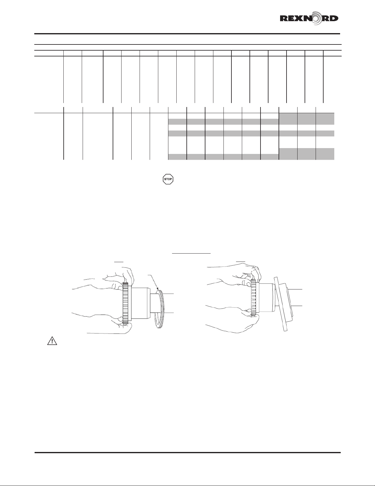
4. Mount Seals (Cover T20) & Hubs
DANGER!
Be sure to disengage the electrical power and any other sources of potential energy before you perform
work on the hub and coupling assembly.
4.1. Examine the coupling assembly to insure there is no visible damage.
4.2. Clean the hub bores and shafts using lint free cloth. Remove any nicks or burrs.
4.3. When assembled, the key(s) should have a close side-to-side fit in the keyway in the hub and shaft, with a slight clearance over the top of
the key.
4.4. Place the seal rings and ½ cover for T20 on shafts before mounting hubs.
T10
T20
MOUNT
SEAL
FIRST
NOTE:
flush here
CAUTION: When heating hubs is required, an oven is preferred and an open flame is not recommended.
If flame heating is considered mandatory, it is important to provide uniform heating to avoid distortion
NOTE:
flush here
and excessive temperature. A thermal stick applied to the hub surface will help determine the hub
temperature.
DANGER!
Touching hot hubs causes burns. Wear safety gloves to avoid contact with hot surfaces.
5. Straight Bore with Clearance/Slip Fit
5.1. Install the key(s) in the shaft.
5.2. Check to be sure that the set screw(s) in the hub does not protrude into the keyway or the bore. Remove or back out the set screw to
provide clearance during assembly.
5.3. Slide the hub up the shaft to the desired axial position.
428-111 Rexnord Industries, LLC, 5555 S. Moorland Rd., New Berlin, WI 53151-7953
02/2012 Telephone: 262-796-4060 Fax: 262-796-4064
Supersedes manuals 428-110, 112, 210 - 04/2005 e-mail: info@rexnord.com web: www.rexnord.com

Installation and Maintenance Instructions • Falk Steelflex
Type T10 & T20 (Page 5 of 9)
5.4. Assemble and tighten the set screw(s) using a calibrated torque wrench to the values shown in Table 2.
Table 2 - Set Screw Tightening Torque
Screw Size M6 M8 M10 M12 M16 1/4" 3/8"
Hex Head Key Size M3 M4 M5 M6 M8 1/8" 3/16"
Tightening torque
Nm 6 12 25 50 100 8 25
lb-in 55 110 220 440 880 70 220
CAUTION: Never use two set screws with one on top of the other in the same tapped hole.
6. Straight Bore with Interference Fit
6.1. Accurately measure the bore and shaft diameters to assure proper fit.
6.2. Install the key(s) in the shaft.
6.3. Heat the hub in an oven until the bore is sufficiently larger than the shaft.
6.4. 275°F (135°C) is usually sufficient for carbon steel hubs. Do not exceed 400°F (205°C).
6.5. With the hub expanded, install it quickly on the shaft to the desired axial position. A pre-set axial stop device can be helpful.
®
Figure 3 - Shaft end to hub face measurement example. Figure 4 - Dial indicator placement for axial draw
measurement example.
7. Taper Bore
7.1. Check for acceptable contact pattern between the hub and the shaft.
7.2. Put the hub on the shaft, keeping the keyways (if existing) aligned.
7.3. Lightly tap the face of the hub with a soft mallet. The resultant position will provide a starting point for the hub axial draw up.
7.4. Use a depth micrometer to measure the distance from the shaft end to the hub face, as shown in Figure 3. Record the dimension.
7.5. Mount a dial indicator to read axial hub advancement, as shown in Figure 4. Alternatively, the indicator can be positioned to contact the
end of the hub. Set the indicator to “zero”.
7.6. Remove the hub and install the key(s) in the shaft.
7.7. Heat the hub in an oven until the bore is sufficiently larger than the shaft.
7.8. 350°F (177°C) is usually sufficient for carbon steel hubs. Do not exceed 500°F (260°C).
7.9. Higher temperatures may be required for higher interference fit levels where alloy steel hubs may be encountered. A general rule to
consider is that for every 160°F increase in temperature, steel will expand 0.001 inch for every inch of shaft diameter (or 0.029 mm/100°C).
When calculating temperatures, also consider additional expansion to provide clearance and allow for a loss of heat and subsequent
shrinkage during the handling process.
7.10. With the hub expanded, install it quickly on the shaft to the “zero” set point. Continue to advance the hub up the taper to the desired
axial position, as defined by Rexnord’s customer. Use the indicator as a guide only. A pre-set axial stop device can be helpful.
7.11. Inspect the assembly to verify that the hub is properly positioned. Consult Rexnord if necessary.
7.12. Install any hub axial retention device (if any) in accordance with the equipment manufacturer’s specifications.
Rexnord Industries, LLC, 5555 S. Moorland Rd., New Berlin, WI 53151-7953 428-111
Telephone: 262-796-4060 Fax: 262-796-4064 02/2012
e-mail: info@rexnord.com web: www.rexnord.com Supersedes manuals 428-110, 112, 110 - 04/2005

Installation and Maintenance Instructions • Falk Steelflex
®
(Page 6 of 9) Type T10 & T20
8. Shaft alignment
ATTENTION! Soft Foot – The equipment must rest flat on its base. If one or more feet of the machine are shorter, longer, or angled in
some way to prevent uniform contact (a condition commonly known as “soft foot”) it must now be corrected.
ATTENTION! To improve the life of the coupling, the shafts must be aligned to minimize deflection of the flexing grids. Shaft alignment
is required in the axial, parallel, and angular directions, with each of these values not to exceed the recommended installation limits
shown in Tables 4 and 5. Shaft alignment can be measured using various established methods, including Laser Alignment, Reverse
Dial Indicator, and Rim and Face. Refer to Rexnord bulletin 538-214 “Coupling Alignment Fundamentals” for instructions regarding shaft
alignment.
8.1. Close gap coupled couplings
Use an inside micrometer or a spacer bar equal in thickness as shown below at 90° intervals to measure the distance between
hubs to gap specified in Table 3.
Type T10 Type T20
Table 3 - Gap Dimension
GAP +/- 10% 1020T - 1090T 1100T - 1110T 1120T - 1200T 1210T - 1260T
Inch 0.125 0.188 0.250 0.500
mm 3 5 6 13
8.2. The “Angular Misalignment” value is the maximum difference between the measurements X and Y taken at opposite ends of the
hub flanges, as shown in Figure 5.
Figure 5 - Angular misalignment
Table 4 - Maximum angular misalignment value
Angular Size 1020T 1030T 1040T 1050T 1060T 1070T 1080T 1090T 1100T 1110T 1120T 1130T 1140T
X-Y
Inch 0.003 0.003 0.003 0.004 0.005 0.005 0.006 0.007 0.008 0.009 0.01 0.012 0.013
mm 0.08 0.08 0.08 0.10 0.13 0.13 0.15 0.18 0.20 0.23 0.25 0.30 0.33
Angular Size 1150T 1160T 1170T 1180T 1190T 1200T 1210T 1220T 1230T 1240T 1250T 1260T
X-Y
Inch 0.016 0.018 0.020 0.022 0.024 0.027 0.029 0.032 0.035 0.038 0.042 0.046
mm 0.406 0.457 0.508 0.559 0.610 0.686 0.737 0.813 0.889 0.965 1.070 1.170
428-111 Rexnord Industries, LLC, 5555 S. Moorland Rd., New Berlin, WI 53151-7953
02/2012 Telephone: 262-796-4060 Fax: 262-796-4064
Supersedes manuals 428-110, 112, 210 - 04/2005 e-mail: info@rexnord.com web: www.rexnord.com

Installation and Maintenance Instructions • Falk Steelflex
8.3. The “Parallel Misalignment” value (P) is the offset between the centers of the hubs, as shown in Figure 6.
Figure 6 - Parallel misalignment
Table 5 - Maximum difference P
Parallel
Offset
P
Size 1020T 1030T 1040T 1050T 1060T 1070T 1080T 1090T 1100T 1110T 1120T 1130T 1140T
Inch 0.006 0.006 0.006 0.008 0.008 0.008 0.008 0.008 0.010 0.010 0.011 0.011 0.011
mm 0.150 0.150 0.150 0.200 0.200 0.200 0.200 0.200 0.250 0.250 0.280 0.280 0.280
®
Type T10 & T20 (Page 7 of 9)
Parallel
Offset
P
Size 1150T 1160T 1170T 1180T 1190T 1200T 1210T 1220T 1230T 1240T 1250T 1260T
Inch 0.012 0.012 0.012 0.015 0.015 0.015 0.018 0.018 0.019 0.019 0.020 0.020
mm 0.305 0.305 0.305 0.381 0.381 0.381 0.457 0.457 0.483 0.483 0.508 0.508
9. Coupling Grid installation
9.1. For T20 inser t gasket between hubs. Pack gap and grooves with specified lubricant before inserting grid. When grids are
furnished in two or more segments, install them so that all cut ends face eachother (as detailed in the picture below); this will
assure correct grid contact with non-rotating pins in cover halves. Spread the grid slightly to pass over the coupling teeth and
seat with a soft mallet
Type T10
Type T20
10. Cover assembly
10.1. Pack the spaces between and around the grid with as much lubricant as possible and wipe off excess flush with top of grid.
T10: Position seals on hubs to line up with grooves in cover. Position gaskets on flange of lower cover half and assemble
covers so that the match marks are on the same side. If shafts are not level (horizontal) or coupling is to be used
vertically, assemble cover halves with the lug and match.
T20: Slide cover halves with seals onto hubs and position with lube holes 180° apart (90° apart for Sizes 1150 thru
1170). Line up cover and gasket bolt holes and secure with fasteners; tighten to torque specified in Table 6
Type T10
Rexnord Industries, LLC, 5555 S. Moorland Rd., New Berlin, WI 53151-7953 428-111
Telephone: 262-796-4060 Fax: 262-796-4064 02/2012
e-mail: info@rexnord.com web: www.rexnord.com Supersedes manuals 428-110, 112, 110 - 04/2005
Type T20

Installation and Maintenance Instructions • Falk Steelflex
®
(Page 8 of 9) Type T10 & T20
Table 6 - Cover fastener tightening torque
Cover Fastener
Tightening
T10
T20
Cover
Fastener
Tightening
T10
T20
10.2. Operating limits for Steelflex Couplings
Angular Size 1020T 1030T 1040T 1050T 1060T 1070T 1080T 1090T 1100T 1110T 1120T 1130T 1140T
X-Y
Size
1020T 1030T 1040T 1050T 1060T 1070T 1080T 1090T 1100T 1110T 1120T 1130T 1140T
lb-in 100 100 100 200 200 200 200 200 312 312 650 650 650
Nm 11.3 11.3 11.3 22.6 22.6 22.6 22.6 22.6 35.0 35.0 73.4 73.4 73.4
lb-in
Nm
Size 1150T 1160T 1170T 1180T 1190T 1200T 1210T 1220T 1230T 1240T 1250T 1260T
lb-in 650 650 1300 1300 1300 2300 2300 3580 3580 5350 5350 5350
Nm 73.4 73.4 146.9 146.9 146.9 259.9 259.9 404.5 404.5 604.5 604.5 604.5
lb-in 650 1300 1300
Nm 73.4 146.9 146.9
Inch 0.010 0.012 0.013 0.016 0.018 0.020 0.024 0.028 0.033 0.036 0.040 0.047 0.053
mm 0.25 0.30 0.33 0.41 0.46 0.51 0.61 0.71 0.84 0.91 1.02 1.19 1.35
100 100 100 200 200 200 200 200 260 260 260 650 650
11.3 11.3 11.3 22.6 22.6 22.6 22.6 22.6 29.4 29.4 29.4 73.4 73.4
Table 7 - Angular Operation limits
Angular Size 1150T 1160T 1170T 1180T 1190T 1200T 1210T 1220T 1230T 1240T 1250T 1260T
X-Y
Parallel Offset Size 1020T 1030T 1040T 1050T 1060T 1070T 1080T 1090T 1100T 1110T 1120T 1130T 1140T
P
Parallel Offset Size 1150T 1160T 1170T 1180T 1190T 1200T 1210T 1220T 1230T 1240T 1250T 1260T
P
Inch 0.062 0.070 0.079 0.089 0.097 0.107 0.118 0.129 0.142 0.154 0.169 0.183
mm 1.57 1.79 2.01 2.26 2.46 2.72 3.00 3.28 3.61 3.91 4.29 4.64
Table 8 - Parallel Operation limits
Inch 0.012 0.012 0.012 0.016 0.016 0.016 0.016 0.016 0.02 0.02 0.022 0.022 0.022
mm 0.300 0.300 0.300 0.410 0.410 0.410 0.410 0.410 0.510 0.510 0.560 0.560 0.560
Inch 0.024 0.024 0.024 0.030 0.030 0.030 0.036 0.036 0.038 0.038 0.040 0.040
mm 0.610 0.610 0.610 0.762 0.762 0.762 0.914 0.914 0.965 0.965 1.020 1.020
11. Coupling lubrication
Type T10 Type T20
LTG Coupling grease
The High centrifugal forces encountered in couplings separate the base oil and thickener of general purpose greases. Heavy thickener, which
has no lubrication qualities, accumulates in the grid – groove area of Steelflex couplings resulting in premature hub or grid failure unless
periodic lubrication cycles are maintained.
428-111 Rexnord Industries, LLC, 5555 S. Moorland Rd., New Berlin, WI 53151-7953
02/2012 Telephone: 262-796-4060 Fax: 262-796-4064
Supersedes manuals 428-110, 112, 210 - 04/2005 e-mail: info@rexnord.com web: www.rexnord.com

Installation and Maintenance Instructions • Falk Steelflex
Type T10 & T20 (Page 9 of 9)
Falk Long Term Grease (LTG) was developed specifically for couplings. It resists separation of the oil and thickener. The consistency of Falk
LTG changes with operating conditions. Working of the lubricant under actual service conditions causes it to become semifluid while the
grease near the seals will set to a heavier grade, helping to prevent leakage. LTG is highly resistant to separation, easily out performing all
other lubricants tested. The resistance to seperation allows the lubricant to be used for relatively long periods of time.
Steelflex couplings initially lubricated with LTG will not require re-lubrication until the connected equipment is stopped for servicing. If a
coupling leaks grease, or is exposed to extreme environments, more frequent lubrication may be required.
USDA APPROVAL
LTG has the United States Department of Agriculture Food Safety & Inspection Service approval for applications where there is no possibility
of contact with edible products. (H-2 ratings)
If Falk LTG grease is not used in coupling use an NLGI EP #2 type grease specific for couplings with rust and oxidation inhibitors that do
not corrode steel or swell or deteriorate synthetic seals. This applies for general applications where the coupling will operate in ambient
temperatures of -18º C to 66ºC (0ºF to 150ºF).
Consult a local lubricant representative for available products in your area with the required weight and lubricant standard requirements as
listed below.
11.1. Lubricate coupling with correct amount of lubricant specified on table 9.
®
Table 9: Lubrication amount
Lube Weight Size 1020T 1030T 1040T 1050T 1060T 1070T 1080T 1090T 1100T 1110T 1120T 1130T 1140T
T10/T20
Lube Weight Size 1150T 1160T 1170T 1180T 1190T 1200T 1210T 1220T 1230T 1240T 1250T 1260T
T10/T20
If coupling leaks grease, is exposed to extreme temperatures, excessive moisture or experiences frequent reversals or axial movements;
more frequent lubrication may be required.
lb 0.06 0.09 0.12 0.15 0.19 0.25 0.38 0.56 0.94 1.10 1.60 2.00 2.50
kg 0.03 0.04 0.05 0.07 0.09 0.11 0.17 0.25 0.43 0.51 0.74 0.91 1.14
lb 4.3 6.2 7.7 8.3 9.7 12.4 23.2 35.4 53.0 74.5 110.5 148.1
kg 1.95 2.81 3.49 3.76 4.40 5.62 10.5 16.1 24.0 33.8 50.1 67.2
CAUTION: Remove grease fitting and make certain all plugs are inserted after lubricating.
12. ANNUAL MAINTENANCE
12.1. For extreme or unusual operating conditions, check coupling more frequently.
12.2. Check coupling alignment per steps on page 6. If the maximum operating misalignment values are exceeded, realign the
coupling to the recommended installation limits. See Table 4, 5, 7 and 8 for installation and operating alignment limits.
12.3. Check tightening torques of all fasteners.
12.4. Inspect seal ring and gasket to determine if replacement is required. If leaking grease, replace.
12.5. When connected equipment is serviced, disassemble the coupling and inspect for wear. Replace worn parts. Clean grease from
coupling and repack with new grease. Install coupling using new gasket as instructed in this manual.
Periodic Lubrication
The required frequency of lubrication is directly related to the type of lubricant chosen, and the operating conditions. Steelflex couplings
lubricated with common industrial lubricants, such as those shown in Table 9, should be relubed annually. The use of Falk Long Term Grease
(LTG) will allow relube intervals to be extended to beyond five years. When relubing, remove both lube plugs and insert lube fitting. Fill with
recommended lubricant until an excess appears at the opposite hole.
Rexnord Industries, LLC, 5555 S. Moorland Rd., New Berlin, WI 53151-7953 428-111
Telephone: 262-796-4060 Fax: 262-796-4064 02/2012
e-mail: info@rexnord.com web: www.rexnord.com Supersedes manuals 428-110, 112, 110 - 04/2005
 Loading...