

Page 1
Falk™ Horizontal Shaft Backstops • Oil Seal Replacement
Type NRT • Sizes 70-180, 1070-1185 (Page 1 of 3)
How To Use This Manual
This manual applies to standard Falk Type NRT backstops.
This manual provides detailed instructions on oil seal
replacement. Use the following Table of Contents to locate
required information.
Table of Contents
Oil Seal Replacement (Cast Iron End Covers)...........1-2
Backstop Removal ...............................1
Backstop Disassembly .............................1
Seal Replacement ................................2
Backstop Assembly ...............................2
Backstop Installation ..............................2
Oil Seal Replacement (Fabricated Steel End Covers)......2-3
CAREFULLY FOLLOW THE INSTRUCTIONS IN THIS
MANUAL FOR OPTIMUM PERFORMANCE AND TROUBLE
FREE SERVICE.
Introduction
This manual covers oil seal replacement for both cast iron and
fabricated steel end covers. See Page 2 for oil seal
replacement for backstops with fabricated steel end covers.
BACKSTOP SEAL REPLACEMENT — For Backstops
with Cast Iron End Covers, See Figure 3, Page2.
CAUTION: Remove all external loads from drive before
servicing drive or accessories. Do not damage cam or hub
face: new seals will leak if seal contacting surface is marred.
Do not use abrasive material on seal contacting surface.
Required Equipment
In addition to standard mechanic’s tools, the following
equipment is required: hoist, sling, torque wrench, dial
indicator with stand or depth micrometer and puller.
CAUTION: Do not attempt to service or remove backstop before
removing load. When removing backstop from shaft, do not
apply heat to the backstop. Apply axial force to the hub of the
backstop only.
Backstop Removal
1. Drain and discard lubricant in an environmentally safe
method.
2. Remove oil sight gauge and breather assembly and insert
pipe plugs in cover holes.
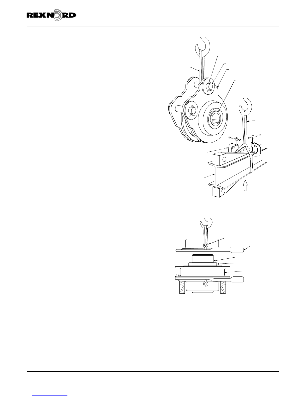
3. Remove torque arm. Refer to Figure 1 for proper method
of supporting and lifting.
4. Reassemble torque arm pins in backstop and lock in place
with cotter pins for lifting.
5. If the backstop is furnished with a axial retaining collar(s),
loosen set screws and mounting bolts and remove collar.
Remove burrs on shaft caused by set screws.
6. Remove backstop from shaft. Apply force to the inner cam
of the backstop only. (Figure 1)
7. Thoroughly clean exterior of backstop with clean solvent to
prevent dirt from falling into the backstop when disassembling.
8. Position backstop on clean work surface with bore vertical.
Figure 1
COTTER PIN
NYLON SLING
CLAMPS TO PREVENT
SLING FROM SLIPPING
OFF "I" BEAM
TORQUE ARM
TORQUE ARM PIN
END COVER
CAM OR HUB FACEPUSH ON THIS FACE
WHEN INSTALLING
BACKSTOP ON SHAFT
BALANCE
POINT
NYLON
SLING
Support lower end cover with wood blocks. (Figure 2)
Figure 2
LIFT
EYE BOLT IN
INNER CAM
BEARING
OUTER RACE
JACKSCREW HOLES
END COVER
Backstop Disassembly
9. Remove upper end cover bolts and end cover using
eyebolts as jackscrews for separation and lifting. (Figure 2)
Do not remove cam, bearings, stop lugs, springs or roller
cage assembly; removal will void applicable warranties.
10.Remove and note number of gaskets; discard old gaskets.
11.Clean outer race gasket area.
12.Remove grease from around the seals if the grease purge
feature has been used. Drive out seals and remove sealing
compound from mounting surface. Clean entire end cover
with clean non-flammable solvent and wipe dry.
Rexnord Industries, LLC, Geared Products, P.O. Box 492, Zip 53201-0492 568-130
3001 W. Canal St., Zip 53208-4200, Milwaukee, WI USA Telephone : 414-342-3131 February 2009
Fax: 414-937-4359 e-mail: [email protected] web: www.rexnord.com Supersedes 11-01
Page 2
Oil Seal Replacement • Falk™ Horizontal Shaft Backstops
SPRINGS
(Page 2 of 3) Sizes 70-180, 1070-1185 • Types NRT
Seal Replacement
13. Check seal surface for any damage prior to installing new
seals. Install one seal at a time. Coat both seal outside
diameters with Permatex #3 or equivalent sealant.
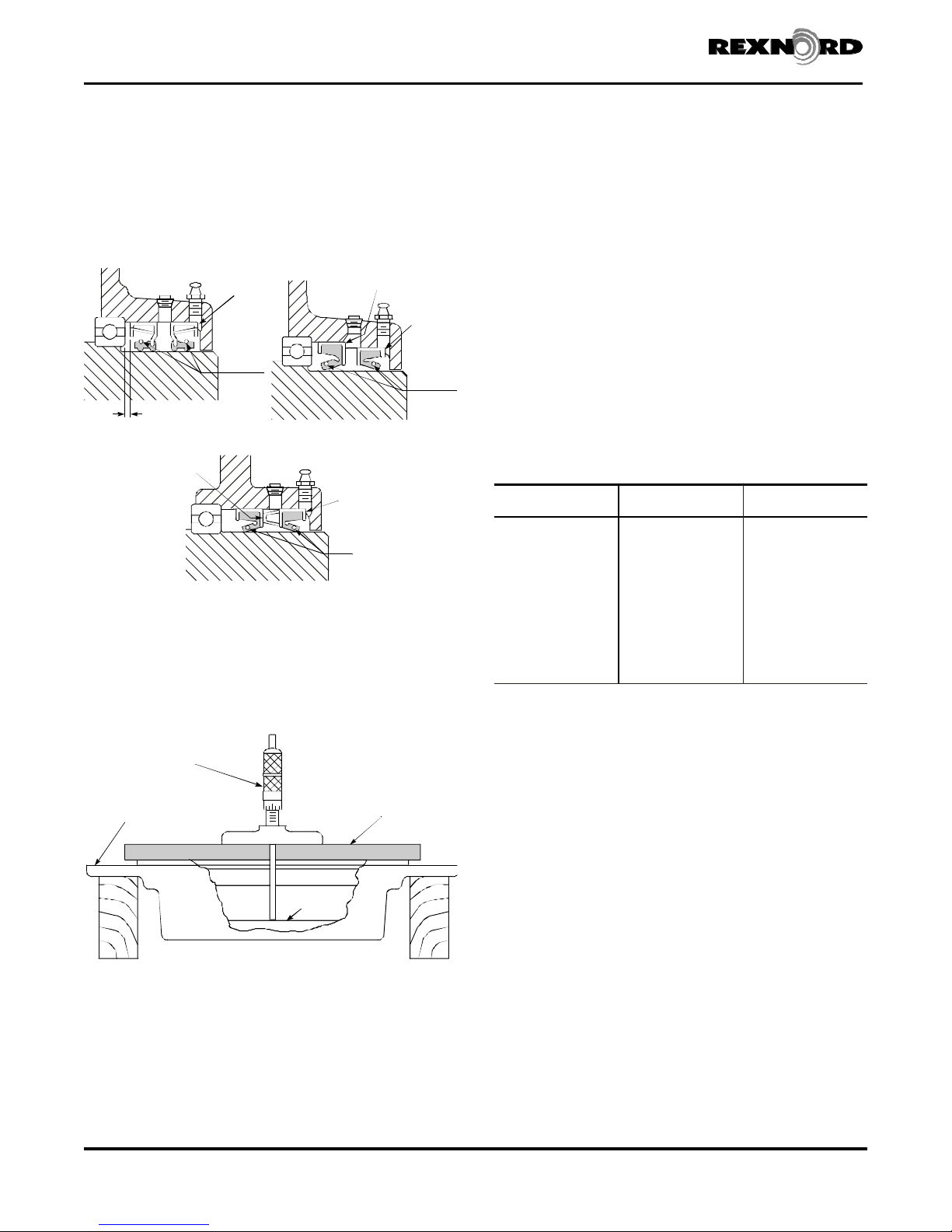
14. OUTER SEAL — Position the outer seal squarely in the end
cover with the garter spring positioned per Figure 3.
NOTE: Use seal with smaller outer diameter as outer seal
for Sizes 130 thru 170 and Sizes 1130 thru 1175.
OUTER
SEAL
SEAT
INNER
CAM
.12” (3mm) APPROX.
CLEARANCE
SIZES 70 THRU 120
SIZES 1070 THRU 1125
INNER SEAL (SEAT
AGAINST LUG)
Figure 3
GARTER
SPRINGS
SIZES 130 THRU 170
SIZES 1130 THRU 1175
INNER
CAM
SIZE 180
SIZES 1180/1185
15. Place a square ended cylindrical tool against the seal and
press or lightly tap the tool (not the seal) until the seal is
seated against the shoulder. (Figure 3)
16. Check seal runout with a depth micrometer, dial indicator
or bar micrometer as shown in Figure 4. Runout must not
exceed .010” (0.25mm) TIR.
Figure 4
DEPTH
MICROMETER
END COVER
INNER SEAL SEAT
INNER
CAM
OUTER
SEAL
SEAT
GARTER
SPRINGS
PARALLEL
OUTER
SEAL
SEAT
GARTER
Backstop Assembly
18.Coat seal lips and chamber between seals with NLGI #2
grease. Hand pack grease cavity between inner and outer
seal with NLGI #2 grease. Reinstall end cover and the
same number of new gaskets as noted in Step 10. Do not
use gaskets made from substitute material; use only the
new gaskets furnished by the Factory.
19.Reinstall end cover fasteners but do not tighten; this will
facilitate torque arm pin assembly.
20.Turn backstop over and replace seals in opposite end
cover per Steps 9 thru 19.
21.Align end covers by inserting torque arm pins. Tighten all
end cover fasteners to the torque shown in Table 1.
Backstop Installation
22.Refer to Manual 568-110 for backstop installation, oil sight
gauge assembly and lubrication recommendations.
TABLE 1 — End Cover Fastener
Tightening Torque
Backstop
Size
70 & 1070/1075 .500”-13UNC 1,325(150)
80 & 1080/1085 .500”-13UNC 1,325(150)
90 & 1090/1095 .500”-13UNC 1,325(150)
100 & 1100/1105 .500”-13UNC 1,325(150)
110 & 1110/1115 .625”-11UNC 2,550(290)
120 & 1120/1125 .625”-11UNC 2,550(290)
130 & 1130/1135 .750”-10UNC 4,425(500)
140 & 1140/1145 .750”-10UNC 4,425(500)
150 & 1150/1155 .875”-9UNC 7,100(800)
160 & 1160/1165 .875”-9UNC 7,100(800)
170 & 1170/1175 .875”-9UNC 7,100(800)
180 & 1180/1185 1.000”-8UNC 10,400(1180)
H
Do not oil fasteners and locknuts or use Loctite compound.
BACKSTOP SEAL REPLACEMENT —
with Fabricated Steel End Covers, See Figures 4,5, and 6 on
Page 3.
CAUTION: Remove all external loads from drive before
servicing drive or accessories. Do not damage cam or hub
face: new seals will leak if seal contacting surface is marred.
Do not use abrasive material on seal contacting surface.
Grade 8
Cap screw Size
Tightening Torque H
lb-in (Nm)
For Backstops
SEAL
17. INNER SEAL — Install the inner seal per Steps 15 and 16
and as follows:
Sizes 70 thru 120 & Sizes 1070 thru 1125 — Install to
depth shown in Figure 3.
Sizes 130 thru 170 & Sizes 1130 thru 1175 — Seat as
shown in Figure 3.
Size 180 & Sizes 1180 thru 1185 — Seals have built-in
spacer lugs. Lugs of inner seal are to be in contact with
case of outer seal.
1. To prevent dirt from falling into the backstop, thoroughly
clean exterior of backstop with clean non-flammable
solvent.
2. If removing backstop, refer to BACKSTOP REMOVAL on
Page 1.
3. Remove labyrinth shroud (See Figure 7, Page 3) from
backstop. Clean cam or hub face with solvent and remove
all sharp edges. Use a sharp center punch to lightly punch
the seal case as a guide for the drill. Check seal surface
for any damage prior to installing new seals.
4. Wrap several turns of tape around the drill approximately
.250” (6mm) from the drill point to prevent the drill from
entering too deeply into the housing and damaging the
bearing (inner seal only). Grease or magnetize the drill to
help retain the chips. Drill two .125” (3mm) diameter holes
Rexnord Industries, LLC, Geared Products, P.O. Box 492, Zip 53201-0492568-130
3001 W. Canal St., Zip 53208-4200, Milwaukee, WI USA Telephone: 414-342-3131February 2009
Fax: 414-937-4359 e-mail: [email protected] web: www.rexnord .comSupersedes 11-01
Page 3
Falk™ Horizontal Shaft Backstops • Oil Seal Replacement
Type NRT • Sizes 70-180, 1070-1185 (Page 3 of 3)
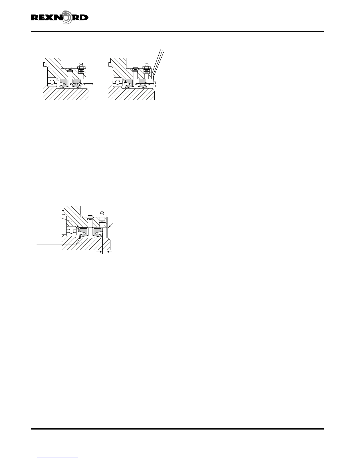
Figure 5 Figure 6
in the seal case 180° apart. Control the angle of the drill
as illustrated in Figure 5 to prevent damage to the cam.
5. Insert two #10-.750” sheet metal screws into the seal
leaving .500” (13mm) of the screw protruding from the
seal face. DO NOT drive the screw more than .250”
(6mm) beyond seal face or bearing damage may occur
(inner seal only). Use a claw type pry bar under the screw
head as shown in Figure 6, and lift the seal out. Remove
all chips. Use a magnet to remove the chips that fall into
the bore. Flush the drive to remove chips from the bearing.
Remove Permatex from housing bore.
6. Install one seal at a time. Coat both seal outside diameters
with Permatex #3 or equivalent sealant.
Figure 7
CAUTION: An important part of the Falk NRT backstop
manufacturing process is the full load and overrunning testing
with specially instrumented equipment. Consequently, return
NRT backstops to Rexnord for repair and full load testing.
Except for replacement of oil seals, NRT backstops should not
be dismantled or repaired in the field. If seals are to be
replaced,it is important that the cam and roller assemblies not
be removed from the outer race. Removal will void applicable
warranties.
When writing to Rexnord Service Department concerning
required service, state nature of problem and give complete
date from backstop nameplate; M.O. number, size, date, etc.
INNER SEAL
SHOULDER
GARTER
SPRINGS
SIZES 1070 THRU 1185
LABYRINTH
COVER
.31”(8mm)
APPROX. CLEARANCE
7. INNER SEAL — Position the inner seal squarely in the
bearing cage with the garter spring positioned per Figure 7.
8. Place a square ended cylindrical tool against the seal and
press or lightly tap the tool (not the seal) until the seal is
seated against the shoulder. (Figure 7)
9. Check seal runout with a depth micrometer, dial indicator
or bar micrometer. Runout must not exceed .010”
(0.25mm) TIR. Hand pack the grease cavity formed by the
gap between the inner seal and outer seal with NLGI #2
grease before installing outer seal in Step 10.
10.OUTER SEAL — Install the outer seal per Steps 7 thru 9
and to depth shown in Figure 7.
Rexnord Industries, LLC, Geared Products, P.O. Box 492, Zip 53201-0492 568-130
3001 W. Canal St., Zip 53208-4200, Milwaukee, WI USA Telephone : 414-342-3131 February 2009
Fax: 414-937-4359 e-mail: [email protected] web: www.rexnord.com Supersedes 11-01
 Loading...