

Page 1
Falk™ Fluid Couplings With T schan®Input·Installation & Maintenance
Types HF132 & 132-1
How To Use This Manual
This manual applies to standard Falk Types HF132 & 132-1
couplings. This manual provides detailed instructions on
installation, maintenance, and parts identification. Use the
following Table of Contents to locate required information.
Table Of Contents
General Information ......................Pages1&2
Maintenance ..............................Pages 2
Installation ............................Page2thru 7
CAREFULLY FOLLOW THE INSTRUCTIONS IN THIS
MANUAL FOR OPTIMUM PERFORMANCE AND TROUBLE
FREE SERVICE.
Introduction
Type HF couplings are designed for horizontal operation. Refer
to the Factory for coupling operation other than horizontal or
for limited end float requirements.
Maximize Performance and Life
The performance and life of couplings depend largely upon
how you install and maintain them. Before installing couplings,
make certain that foundations of equipment to be connected
meet manufacturers’ requirements. Check for soft foot. The
use of stainless steel shims is recommended. Measuring
misalignment and positioning equipment within alignment
tolerances is simplified with an alignment computer. These
calculations can also be done graphically or mathematically.
It is recommended that final alignment be checked using either
an alignment computer or graphical analysis. Both methods
allow the incorporation of “cold offsets”, which will
compensate for shaft position changes due to thermal growth.
WARNING: Lockout power source and remove external loads
from the drive before servicing unit or accessories.
WARNING: When opening the drain plug, filler plug or orifice
seal plug of a warm or hot fluid coupling, place a rag over the
plug and loosen the plug slowly to relieve any internal
pressure.
WARNING: Consult applicable local and national safety codes
for proper guarding of rotating members. Guard must not
restrict free flow of air, but the portion of the guard in line with
fusible plugs must be solid construction.
CAUTION: DO NOT PAINT fluid coupling. Painting will
reduce fluid coupling thermal heat dissipation characteristics.
CAUTION: DO NOT spray water on a hot fluid coupling, as
this may result in crackin gof aluminum components.
Identification:
Tschan Coupling — Refer to Figures6&7,Page3,and
Table 4, Page 4.
Fluid Coupling — Size and Type are stamped on coupling
perimeter. Refer to the Factory for replacement parts.
Sizes 270 thru 870 & 1420 thru 1760 (Page 1 of 7)
·
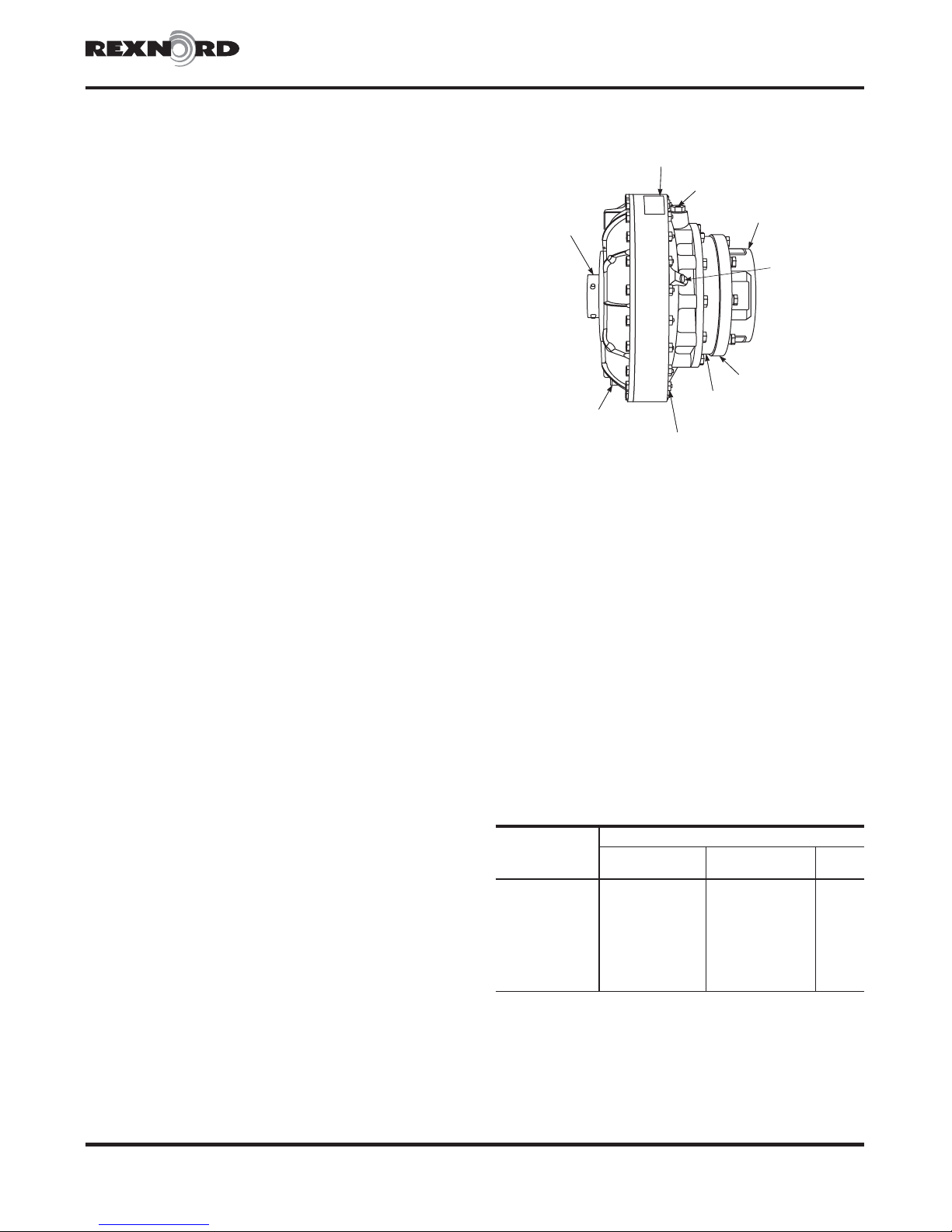
ORANGE LABEL
FILL PLUG
392ºF (200ºC)
HOLLOW SHAFT
DRAIN PLUG
248ºF (140ºC)
Figure 1
PERIMETER
FASTENERS
SHAFT HUB
INPUT ADAPTER
DELAY FILL
CHAMBER
ORIFICE
SEAL PLUG
(1000 SERIES
ONLY)
Fluids
The following specifications and fluids listed in Table 1 apply
to fluid couplings. Refer to the Factory for use of fire resistant
fluids. NOTE: Fluids listed are typical products ONLY and
should not be construed as exclusive recommendations.
ISO Viscosity Grade — 46
Viscosity at 104°F(40°C) — 46 cSt (215 SSU)
Viscosity Index — 105 or greater.
Pour Point — Must be 5°F(3°C) lower than minimum
starting temperature.
Flash Point — 400°F(204°C)
Specific Gravity — 0.87
Antioxidant and Anti-foaming Additives
TABLE 1 — Fluids & Operating Temperatures
Operating Temperature Greater Than:
Manufacturer
Amoco Oil Co.
Exxon Co., USA
Gulf Oil Corp.
Mobil Oil Corp.
Shell Oil Co.
Texaco Inc.
Texaco Canada
Union Oil Co. of Calif.
20°F
(-7°C)
American Ind. Oil 46 American Ind. Oil 46
Teresstic 46
Harmony 46
DTE Medium Mobilfluid 423 SHC 624
Tellus 46
Rando 46 Rando 46
Regal R&O 46
Unax VG 46 Unax VG 46
-20°F
(-29°C)
... ...
... ...
... ...
... ...
-50°F
(-46°C)
...
...
...
Rexnord Industries, LLC, Coupling Group 528-358
5555 S. Moorland Rd., New Berlin, WI 53151-7953 USA Telephone: 262-796-4060 June 2006
Fax: 262-796-4064 e-mail: [email protected] web: www.rexnord.com Supersedes 2-94
Page 2
Installation & Maintenance·Falk™ Fluid Couplings With Tschan® Input
(Page 2 of 7) Sizes 270 thru 870 & 1420 thru 1760
Annual Maintenance
Check shaft coupling alignment on a regular basis. Excessive
misalignment will transfer damaging loads to the connected
equipment and may cause failure.
Check flexible coupling elastomer spider for wear and replace
if necessary.
Check fluid annually or more often if it is subject to
overheating. Overheated fluid which becomes dark in color
and gives off a burnt odor, must be changed. Fluid suppliers
can test coupling fluid samples periodically and recommend
economical change periods based on the rate of degradation.
Continuous operating temperature must not exceed
212°F(100°C).
Lifting
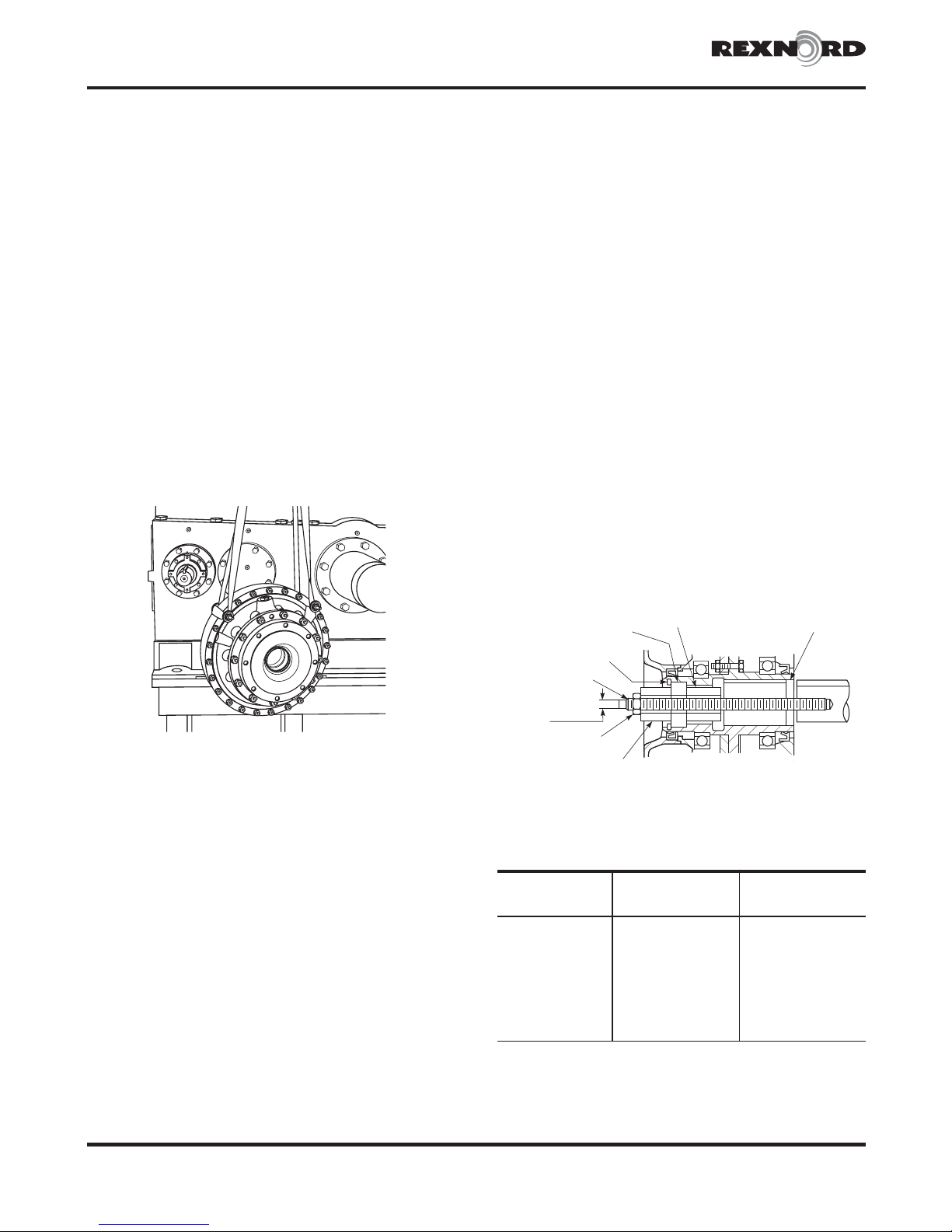
Remove two perimeter fasteners (metric) approximately 90°
apart. Insert threaded rod (Table 3, Page 4) with washers and
nuts, then sling coupling as shown in Figure 2.
Figure 2
Types HF132 & 132-1
·
Installation
Only standard mechanics tools, torque wrenches, feeler
gauges, straight edges, and a bevel protractor with spirit level
or Falk Angle Finder are required to install fluid couplings.
1. Install Fluid Coupling.
a) Lock out starting switch of prime mover.
b) Check for nicks or burrs on driven shaft and in fluid
coupling bore.
c) Check fit of key in keyways and secure in shaft keyway.
d) Coat driven shaft with an anti-seize compound.
e) Install fluid coupling on driven shaft.
1) These couplings are normally furnished with a slight
clearance to light interference fit between coupling
hollow shaft bore and driven shaft. A threaded drive
rod and drawing on plate are required to draw the
coupling onto driven shaft, see Figure 3. Refer to Table
2 for threaded rod and plate dimensions.
CAUTION: DO NOT USE HEAT on fluid coupling
shaft. The driven shaft may be cooled with dry ice to
reduce its size and assist assembly.
2) Screw threaded rod into end of driven shaft.
3) Pass fluid coupling over threaded rod and onto driven
shaft using the starting overbore area for alignment to
driven shaft and keyway.
Figure 3
KEEPER PLATE
RETAINING RING
THREADED ROD
GRIND WRENCH
FLATS
NUT
DRAWING ON PLATE
SPACER
STARTING OVERBORE
TABLE 2 — Threaded Rod & Drawing On
Plate (Dimensions – Inches)
†
†
†
†
†
†
†
Drawing On Plate
OD (Max) x ID x
Thickness (Min)
2.375 x .875 x 2.000
2.625 x 1.000 x 2.000
3.125 x 1.000 x 3.000
3.500 x 1.125 x 3.000
4.250 x 1.438 x 3.000
5.250 x 1.438 x 4.000
5.750 x 1.438 x 5.000
COUPLING
SIZE
270HF
320HF .625-11 UNC x 13 2.250 x .688 x 1.500
370HF .750-10 UNC x 15 (18)
1420HF
1480HF .875- 9 UNC x 19 (23)
1584HF 1.000- 8 UNC x 21 (25)
1660HF 1.250- 7 UNC x 24 (28)
1760HF 1.250- 7 UNC x 27 (32)
870HF
H
SAE Grade 5 (ASTM A449) or equivalent.
†
Number in parenthesis is the minimum length required for Type HFDD
couplings
Threaded Rod
Diameter x Length (Min)
.625-11 UNC x 11 1.750 x .688 x .750
.875- 9 UNC x 17 (21)
1.250- 7 UNC x 30 (35)
H
5555 S. Moorland Rd., New Berlin, WI 53151-7953 USA Telephone: 262-796-4060June 2006
Rexnord Industries, LLC, Coupling Group528-358
Fax: 262-796-4064 e-mail: [email protected] web: www.rexnord.comSupersedes 2-94
Page 3
Falk™ Fluid Couplings With T schan®Input·Installation & Maintenance
Types HF132 & 132-1
4) Assemble spacer, keeper plate and retaining ring (Refer
to Table 3, Page 4, for retaining ring number) in hollow
shaft of fluid coupling, Figure 3, Page 2. Spacer must
be properly seated against keeper plate.
5) Place drawing on plate and nut on threaded rod. Make
certain drawing on plate is seated against keeper plate
and not contacting retaining ring or end of fluid
coupling housing.
6) Draw fluid coupling onto the driven shaft by tightening
nut against drawing on plate. Hold threaded rod end
while tightening nut to prevent shaft rotation. Draw
coupling on until spacer makes contact with the end of
driven shaft.
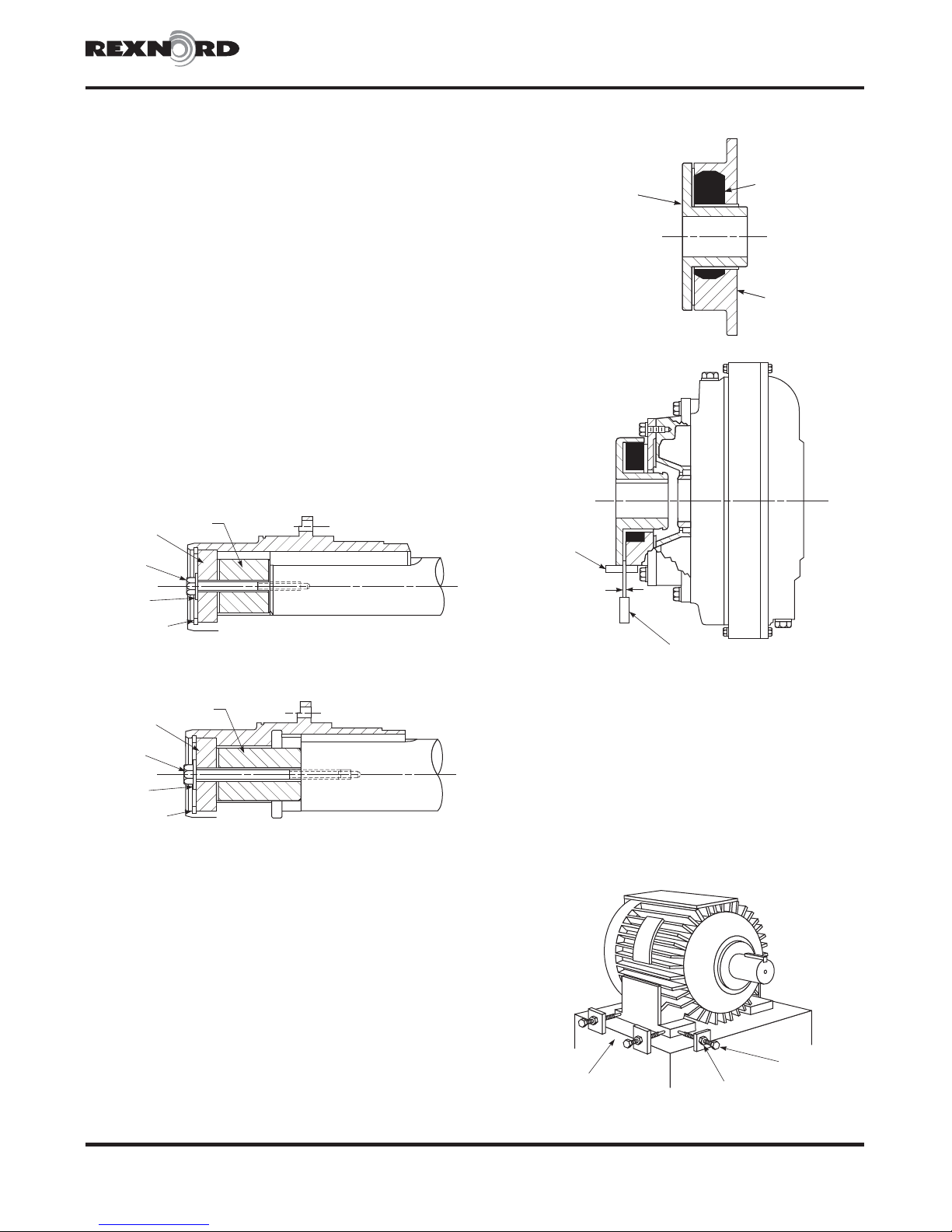
7) Remove threaded rod and drawing on plate. Insert
keeper plate fastener with lock washer through keeper
plate and spacer, Figures 4 and 5. Carefully thread
into tapped hole in driven shaft and tighten to torque
specified in Table 3, Page 4.
g) Reinstall perimeter fasteners and washers. Tighten to
torque specified in Table 3, Page 4.
Figure4–TypeHF132
Sizes 270 thru 870 & 1420 thru 1760 (Page 3 of 7)
·
Figure6—Tschan Type SV
SHAFT
HUB
Figure 7
FLEXIBLE
SPIDER
INPUT
ADAPTER
KEEPER
PLATE
KEEPER PLATE
FASTENER
LOCK
WASHER
RETAINING
RING
Figure5–TypeHF132-1
KEEPER
PLATE
KEEPER PLATE
FASTENER
LOCK
WASHER
RETAINING
RING
SPACER
SPACER
2. Install Adapter and Shaft Coupling.
NOTE: The installation instructions and the method of
alignment provided for the shaft coupling are offered as a
guide only. It is strongly recommended to consult the
flexible coupling manufacturer’s installation and
maintenance instructions.
a) Install input adapter (See Figures 6 and 7) to the fluid
coupling with lock washers and fasteners provided and
tighten to torque specified in Table 3, Page 4. Adapter
register must be properly engaged.
FLAT
RULE
S
THICKNESS
GAUGE
b) Assemble shaft hub (Figure 6) to motor shaft as instructed
in coupling manufacturer’s manual.
c) Insert flexible spider (Figure 6) into Tschan coupling.
d) Position the motor with shaft hub close to the fluid
coupling in approximately the correct position. Engage
motor and shaft hub axially into input adapter of fluid
coupling & elastomer spider of flexible coupling. For
precise motor alignment, the use of adjustment screws
with brackets attached to the bedplate (See Figure 8) is
recommended.
Figure 8
Rexnord Industries, LLC, Coupling Group 528-358
5555 S. Moorland Rd., New Berlin, WI 53151-7953 USA Telephone: 262-796-4060 June 2006
Fax: 262-796-4064 e-mail: [email protected] web: www.rexnord.com Supersedes 2-94
BEDPLATE
ADJUSTMENT
SCREW
LOCKNUT
Page 4
Installation & Maintenance·Falk™ Fluid Couplings With Tschan® Input
(Page 4 of 7) Sizes 270 thru 870 & 1420 thru 1760
Types HF132 & 132-1
·
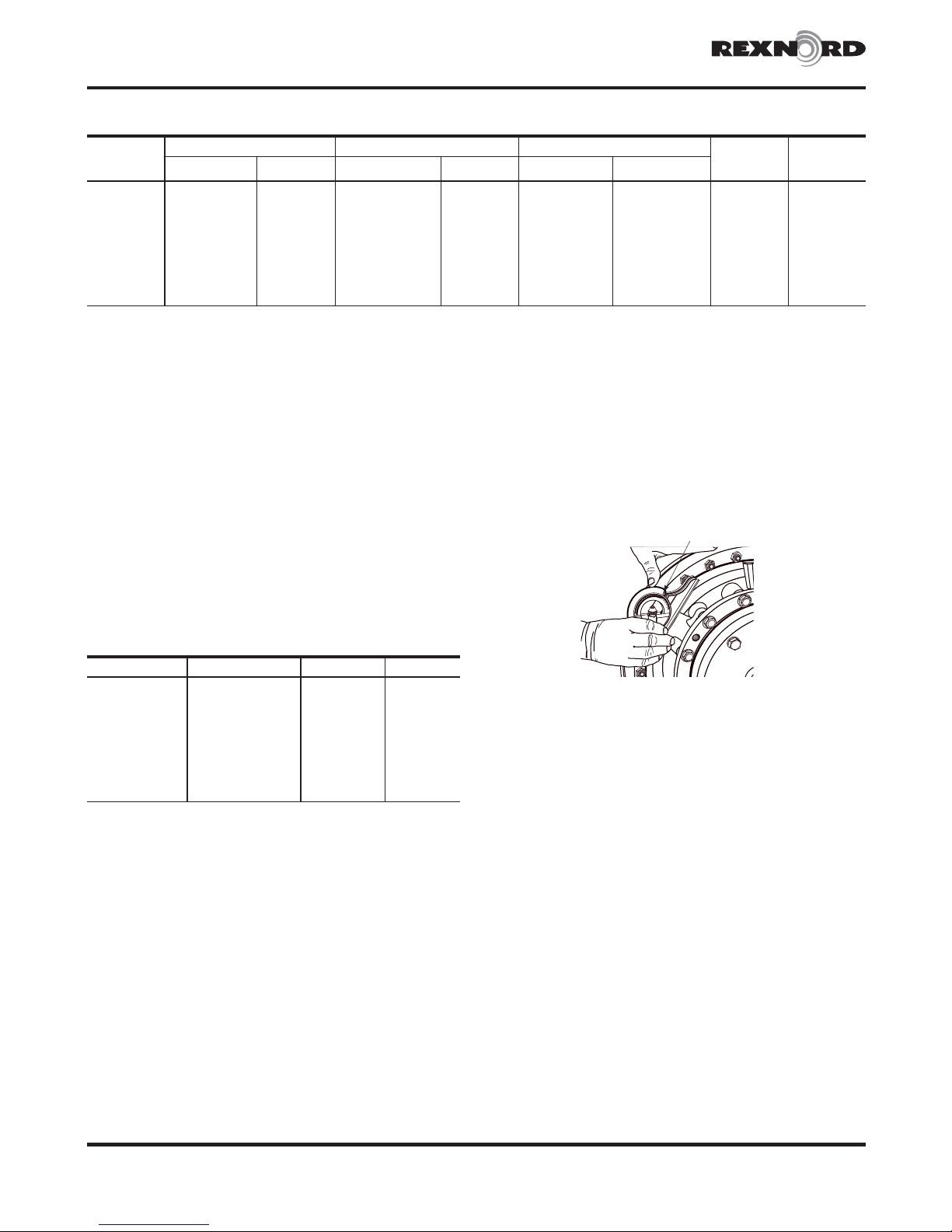
TABLE 3 — Fastener Size And Tightening Torques
COUPLING
SIZE
270HF M8 x 65 15 M8 x 35 15.0 .625-11 60.0 RRN200 .250
320HF
370HF
1420HF M10 x 80 33 M12 x 45 59.0 .875- 9
1480HF
1584HF
1660HF
1760HF
870HF M20 x 180 279 M20 x 75 245.0 1.250- 7
H
Ramsey Spir O Lox®RRN Series or equivalent.
e) The two halves of the Tschan coupling must be parallel
within .004". To accomplish this, align so that a straight
edge rests squarely on both halves as shown in Figure 7,
Page 3, and also at 90° intervals. Check with feelers.
f) While remaining parallel, the two half-couplings must be
checked for angular misalignment. Initially position the
coupling halves using a gauge equal in thickness to the
“S” dimension specified in Table 4. Next, measure the
clearance between the two flanges at 90° intervals.
Compare with the values listed under “S–Range” in Table
4. The space between the flanges must be within this
range and must not vary by more than .008" TIR.
g) Tighten all foundation fasteners and repeat Steps “e” and
“f”. Re-align coupling if necessary.
Perimeter Fasteners(Grade 8.8) Input Adapter Fasteners(Grade 8.8) Keeper Plate Fasteners(SAE Grade 5) Retaining
Size x Length(mm) Torque lb-ft Size x Length(mm ) Torque lb-ft Size-inch Torque lb-ft
M8 x 65 15 M12 x 40 59.0 .625-11 60.0 RRN275 .250
M10 x 80 33 M12 x 45 59.0 .750-10 110.0 RRN275 .375
M10 x 80 33 M12 x 50 59.0 .875- 9 120.0 RRN362 .375
M14 x 100 88 M12 x 55 59.0 1.000- 8 180.0 RRN412 .500
M14 x 120 88 M14 x 65 88.0 1.250- 7 250.0 RRN475 .500
M16 x 150 140 M16 x 60 140.0 1.250- 7 250.0 RRN575 .625
120.0
250.0
Ring
H
No.
RRN312 .375
RRN650 .750
4. Check Fill Angle.
a) Refer to fluid fill label described in Step 3b for required
fill angle.
b) Use a Falk Angle Finder or a bevel protractor with spirit
level set for the required fill angle, and place it on flat
boss of filler hole as shown in Figure 9.
Figure 9
FILL ANGLE
Threaded Rod
for Lifting
Dia-inch
TABLE 4 — Gauge Thickness – Inches
Fluid Coupling Size Tschan Coupling Size S S - Range
270 SV145 .08 .08-.12
320 SV170
370 SV200
1420 SV230 .18 .18-.24
1480 SV260
1584 SV300
1660 SV360
1760 SV360
870 SV400 .30 .30-.36
3. Fill Fluid Coupling
a) Rotate fluid coupling until fill plug is on top and remove it.
(Both fill and drain plugs have metric threads.) Fill plug is
on the input adapter (Tschan coupling) side of coupling,
(Figure 1, Page 1) except for Size 320, where the plug
location is on the opposite side.
b) Install the required amount of fluid shown on the orange
label on fluid coupling perimeter. Fluid must meet the
specifications listed in Table 1, Page 1. Do not remove
fluid fill label, refer to the Factory if label is missing.
c) Before reinstalling fill plug, check fill angle as described in
the following step.
.10 .10-.16
.10 .10-.16
.18 .18-.24
.18 .18-.22
.18 .18-.24
.18 .18-.24
5555 S. Moorland Rd., New Berlin, WI 53151-7953 USA Telephone: 262-796-4060June 2006
Rexnord Industries, LLC, Coupling Group528-358
Fax: 262-796-4064 e-mail: [email protected] web: www.rexnord.comSupersedes 2-94
Page 5
Falk™ Fluid Couplings With T schan®Input·Installation & Maintenance
M
Types HF132 & 132-1
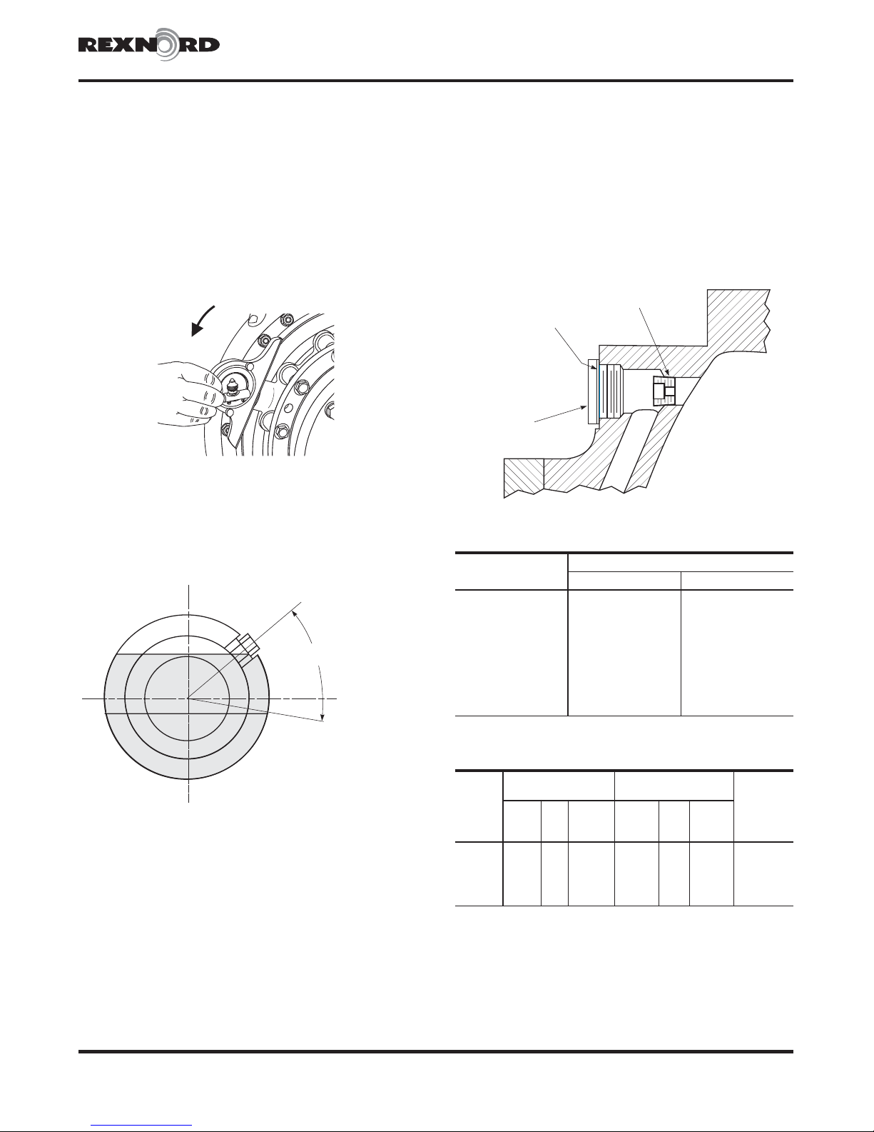
c) Slowly rotate fluid coupling until the required fill angle is
achieved, Figure 10. Fluid must appear at the lip of the
hole. Add or drain fluid until level is correct. Figure 11
shows fill angle range.
d) Reinstall fill plug with seal ring and tighten to required
torque; Sizes 185-270, 22 lb-ft; Sizes 320-1660, 33 lb-ft;
Sizes 1760/2760 and 870, 59 lb-ft.
Figure 10
Sizes 270 thru 870 & 1420 thru 1760 (Page 5 of 7)
·
CAUTION: Increasing the starting time can result in
overheating the fluid coupling and blowing the fusible plugs.
Refer to Table 6 for orifice and seal plug sizes, tightening
torques, and required metric hex “Allen” wrench sizes. Apply
anti-seize compound to the orifice plugs prior to their
assembly. This will assist in the event of future removal. Typical
compounds (or equal) are as follows:
Loctite™ Anti-Seize Thread Compound #767
Dow Corning 1000 High Temperature Anti -Seize Paste
Figure 12
ORIFICE PLUG
SEAL WASHER
SEAL
PLUG
Figure 11
0°
0°
50°(HFN, HFD,)
60°(HFDD)
FILL
RANGE
100° MAXIMUM
MINIMU
}
5. 1000 Series Couplings
The 1000 Series fluid couplings contain 3 orifice plugs(metric
threaded) located near the outer part of the casing. They are
located behind three metric hex socket seal plugs (see Figure 12).
The function of these orifice plugs is to meter the fluid exiting from
the delay fill chamber into the working circuit of the fluid
coupling. These plugs are initially drilled with a 2.5mm hole (Sizes
1420-1660HF) and 3.5mm on Size 1760HF, which results in
acceptable starting times for most applications. Should your
application require increased or reduced starting times, refer to
Table 5 below for other orifice hole sizes and their estimated
affect on starting time. These estimates are based on the change
in flow rate for the fluid to exit the delay fill chamber.
TABLE 5 — Fluid Coupling Starting Times
Orifice Hole Diameter
3/64" (0.0469)
1/16" (0.0625)
5/64" (0.0781)
3/32" (0.0937)
2.5 mm (0.0984)
7/64" (0.1094)
1/8" (0.1250)
3.5 mm (0.1380)
5/32" (0.1562)
3/16" (0.1875)
Estimated Starting Time-%ofOriginal
1420HF - 1660HF 1760HF
440 860
250 490
160 310
110 220
100 200
80 160
60 120
50 100
40 80
30 50
TABLE 6 — Orifice and Seal Plug Sizes
Orifice Plug
COUPLING
SIZE
1420 1/8R BSPT 5 mm 7 18 x 1.5 mm 10 mm 33 18 x 22 x 1.5 mm
1480
1584
1660
1760/2760 1/2R BSPT 10 mm 29 27 x 2.0 mm 17 mm 74 27 x 32 x 2.0 mm
DIN906
Tightening
Hex
Thread
Size
1/4R BSPT 6 mm 11 18 x 1.5 mm 10 mm 33 18 x 22 x 1.5 mm
3/8R BSPT 8 mm 15 22 x 1.5 mm 12 mm 59 22 x 27 x 1.5 mm
3/8R BSPT 8 mm 15 22 x 1.5 mm 12 mm 59 22 x 27 x 1.5 mm
Key
Size
Torque
ft-lb
Thread
Size
Seal Plug
DIN908
Hex
Key
Size
Tightening
Torque
ft-lb
Seal Washer
DIN 7603
Type “A”
Copper
Rexnord Industries, LLC, Coupling Group 528-358
5555 S. Moorland Rd., New Berlin, WI 53151-7953 USA Telephone: 262-796-4060 June 2006
Fax: 262-796-4064 e-mail: [email protected] web: www.rexnord.com Supersedes 2-94
Page 6
Installation & Maintenance·Falk™ Fluid Couplings With Tschan® Input
(Page 6 of 7) Sizes 270 thru 870 & 1420 thru 1760
6. Fusible Plugs
a) Fusible plugs in the fill and drain holes have solder
cores that melt at the temperatures shown in Figure 1,
Page 1. One extra 284°F (140°C) plug is furnished with
each coupling.
b) If solder in fusible plug melts due to overheating from
stalling or overloading, refer to Table 7, Page 7, and
correct the cause of overheating.
CAUTION: DO NOT replace fusible plugs with solid
plugs. Use of solid plugs can result in coupling failure from
overheating unless used in conjunction with a thermal trip
switch. Refer to the Factory for thermal trip switch feature.
c) Replace fusible plugs as instructed in Step 4d.
d) Refill coupling with clean fluid as instructed in Steps 3 and
4,Pages4&5.
Coupling Removal
1. Type 132 & 132-1:
a) Support coupling with sling as shown in Figure 2, Page 2.
b) Remove input adapter.
c) Remove keeper bolt, lock washer, retaining ring, and
keeper plate.
d) Insert threaded removal plate and Spir O Lox®ring into
hollow shaft bore.
e) Coat threads of hydraulic removal cylinder with oil.
Thread cylinder into removal plate until snug.
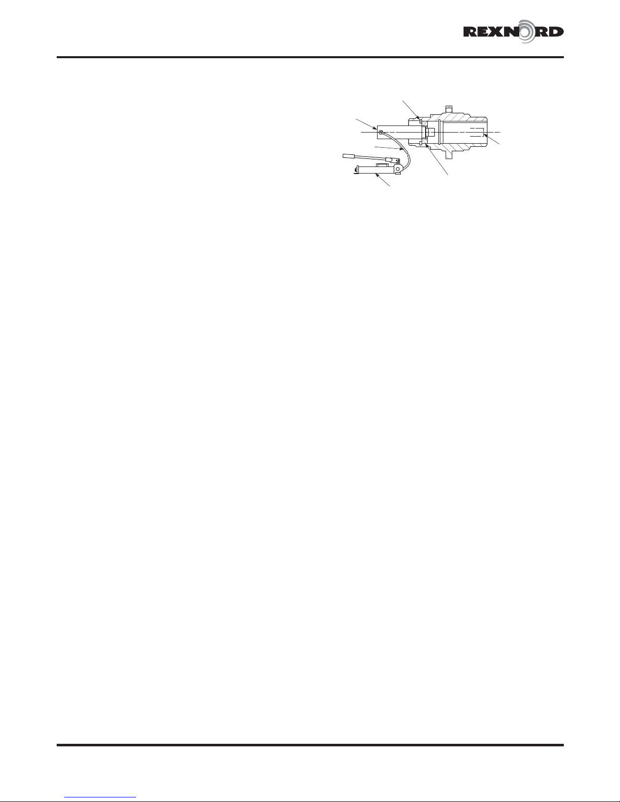
f) Connect Enerpac™ pump (or equal) to cylinder and pump
until fluid coupling is free from shaft. (Refer to Figure 13
for removal setup.) If the cylinder rod is not long enough
to completely remove coupling, it will be necessary to
position a spacer block between the rod and the shaft.
Types HF132 & 132-1
·
Figure 13
SPIR O LOX SNAP RING
CYLINDER
HOSE
ASSEMBLY
HAND PUMP
CYLINDER ROD/
EXTENDED POSITION
INTERNALLY THREADED
REMOVAL PLATE
5555 S. Moorland Rd., New Berlin, WI 53151-7953 USA Telephone: 262-796-4060June 2006
Rexnord Industries, LLC, Coupling Group528-358
Fax: 262-796-4064 e-mail: [email protected] web: www.rexnord.comSupersedes 2-94
Page 7
Falk™ Fluid Couplings With T schan®Input·Installation & Maintenance
Types HF132 & 132-1
Sizes 270 thru 870 & 1420 thru 1760 (Page 7 of 7)
·
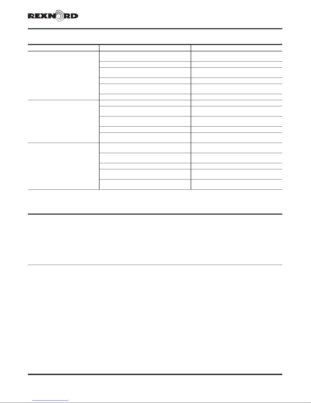
TABLE 7 — Startup And Trouble Shooting
Problem Possible Cause Solution
Drive motor defective or
incorrectly connected.
Driven machine jammed. Check driven machine and remove jam.
Driven shaft fails to
reach specified speed
Fusible plugs melt
Coupling vibration
exceeds acceptable limits
H
Increase fluid fill by decreasing fill angle in 5° increments to a minimum of 50°. If drive shaft still does not reach specified speed, consult the Factory.
Power consumption exceeds
coupling capacity at specified fill angle.
Coupling over or under filled. Re-check fill angle per Step 4, Page 4.
Coupling leaking.
1000 Series - Orifice plug hole plugged. Clean orifice plug hole or use larger hole.
Coupling under filled. Re-check fill angle per Step 4, Page 4.
1000 Series - Orifice plug hole too small or
plugged.
Coupling leaking.
Driven machine jammed. Check driven machine and remove jam.
Power consumption exceeds
coupling capacity of specified fill angle.
Incorrect shaft coupling alignment.
Incorrect shaft coupling alignment
due to thermal growth.
Worn shaft coupling parts. Correct cause of wear and replace worn parts.
Loose foundation, shaft coupling,
or adapter fasteners.
Damaged fluid coupling bearing.
Check motor connection, speed, amperage
draw, and power draw.
H
Correct source of leakage and re-check
fill angle per Step 4, Page 4.
Enlarge orifice hole size (See Table 5 for estimated
start time reduction) or clean plugged holes.
Correct source of leakage and re-check
fill angle per Step 4, Page 4.
H
Re-align per instructions in shaft coupling
service manual.
Check “HOT” alignment and adjust to
compensate for thermal growth.
Check and tighten fasteners accordingly.
Return fluid coupling to Falk for
bearing replacement.
TABLE 8 — Drive Data Records
Equipment Identification .........................................................................................
Motor/Brake Hp [email protected] RPM ...............................
Fluid Coupling Size ............................................................................................
Fill Angle ................................Degrees. .........Fill Volume.......................................Fl.Oz.
Falk Master Order Number ..........................................Date Installed ..................................
Rexnord Industries, LLC, Coupling Group 528-358
5555 S. Moorland Rd., New Berlin, WI 53151-7953 USA Telephone: 262-796-4060 June 2006
Fax: 262-796-4064 e-mail: [email protected] web: www.rexnord.com Supersedes 2-94
 Loading...