


LM35 AND LM45 LAMINATORS
FROM SERIAL NO A670945 (LM45)
FROM SERIAL NO A671035 (LM35)
ILLUSTRATED PARTS LISTS
AND
SERVICE INSTRUCTIONS
Compiled by David Bird Issue No 4
Approved by Paul Aries (Technical Manager) Date 01/07/02

ILLUSTRATED PARTS MANUAL
LM35, LM45 LAMINATORS
Rexel Business Machines, Westbank, Droitwich Spa, Worcestershire. WR9 9AP England
Tel: +44 (0) 1905 771555 Fax: +44 (0) 1905 823374
1
TABLE OF CONTENTS
ILLUSTRATED PARTS MANUAL
LM35 AND LM45 LAMINATORS
Preface Page 2
Illustrations and Parts Lists with
Recommended Spares Pages 3 – 8
Mouldings Page 3 – 4
Head Page 5 – 6
Electrics Page 7 – 8
Service Manual Page 9 – 15
Section 1 Page 9
Section 2 Page 9
Section 3 Page 9
Section 4 Page 10
Section 5 Page 11
Section 6 Page 11
Section 7 Page 11
Section 8 Page 12
Section 9 Page 12
Section 10 Page 13
Section 11 Page 14
Section 12 Page 14
Section 13 Page 15
Section 14 Page 15
Specifications Page 16
Wiring Diagrams Page 17 – 18
LM35 Page 17
LM45 Page 18
Amendment Record Page 19
ILLUSTRATED PARTS MANUAL
LM35, LM45 LAMINATORS
Rexel Business Machines, Westbank, Droitwich Spa, Worcestershire. WR9 9AP England
Tel: +44 (0) 1905 771555 Fax: +44 (0) 1905 823374
2
PREFACE
This manual provides the instructions for the replacement of all the components that may become worn
or damaged. Details of replacement parts and ordering information are given in associated illustrated
parts list. For operating instructions see OI-477-07-96 and laminator carrier instructions see OI-521-0797 for both LM35 and LM45.
Illustrated Parts Lists
For each machine, these give full details of the replacement part numbers with supporting diagrams to
show the location of the components.
Service Instructions
For each machine, these give the recommended servicing procedure with supporting pictorial diagrams
for added clarity
WARNING
1. Check the machine RATING PLATE DETAILS are compatible with the electrical mains supply.
2. Disconnect the electrical mains supply before removing any covers.
3. The machine MUST have a sound Electrical Earth connection.
ILLUSTRATED PARTS MANUAL
LM35, LM45 LAMINATORS
Rexel Business Machines, Westbank, Droitwich Spa, Worcestershire. WR9 9AP England
Tel: +44 (0) 1905 771555 Fax: +44 (0) 1905 823374
3
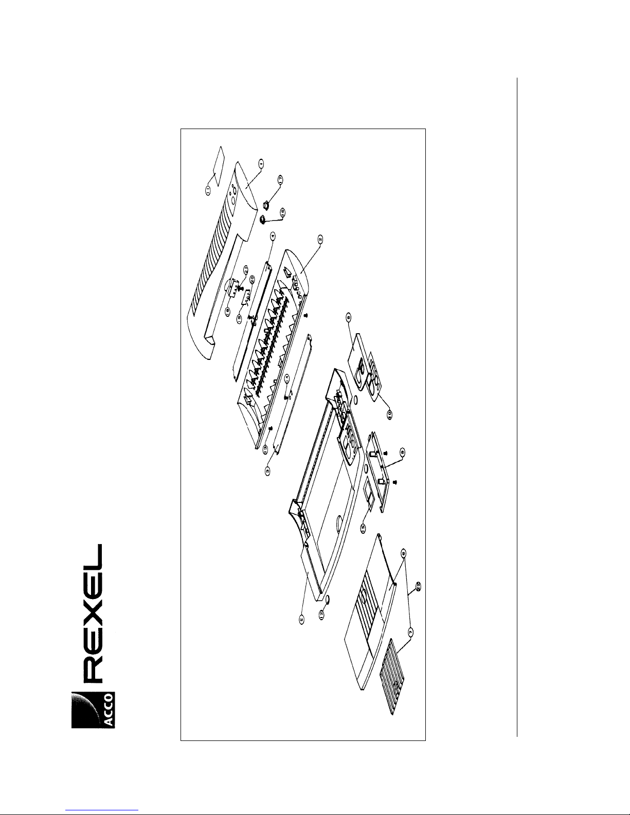
MOULDINGS
NO PART DESCRIPTION 35 45 COMMENT
1 D50543 Top Ellipse Rexel 1 1
2 D50539 Bottom Ellipse 1 1 Made from D50501
3 D50502 Entry Moulding 1 1
4 D50555 Entry Moulding With Printing 1 1
5 D50504 Main Front Shelf 1 1
6 D50505 Main Lid 1 1
7 D50506 Paper Support 1 1
8 D50507 Keypad Cover 1 1
9 D50508 Pcb Cover Plate 1 1
10 D000332 Keypad Decal - 1
11 D000349 LM35 Model No. Decal 1 - NOT SHOWN
11 D000350 LM45 Model No. Decal - 1 NOT SHOWN
12 SL18-294 Rubber Feet 4 4
13 SCR714 M4 X 12 Plasform Pan Head Screw 4 4
14 SCR713 M3 X 8 Plasform Pan Head Screw 2 3
15 D50589 Lcd Cover 1 18 D50578 Fixing Bracket - 1
19 D50579 Paper Deflector Blade - 1
21 PLN31 Plain Washer - 1
22 A50594 MAIN LID COMPLETE 1 1 COMPRISES 6, 7
24 D000185 Service Call Decal 1 1
25 RPLM35 Rating Decal 1 - NOT SHOWN
25 RPLM45 Rating Decal - 1
27 D000368 Carrier Warning Decal 1 - NOT SHOWN.
A50575 MAIN LID ASSEMBLY 1 1 COMPRISES 5, 6, 7, 8

ILLUSTRATED PARTS MANUAL
LM35, LM45 LAMINATORS
Rexel Business Machines, Westbank, Droitwich Spa, Worcestershire. WR9 9AP England
Tel: +44 (0) 1905 771555 Fax: +44 (0) 1905 823374
4
MOULDINGS
ILLUSTRATED PARTS MANUAL
LM35, LM45 LAMINATORS
Rexel Business Machines, Westbank, Droitwich Spa, Worcestershire. WR9 9AP England
Tel: +44 (0) 1905 771555 Fax: +44 (0) 1905 823374
5
HEADS
NO PART DESCRIPTION 35 45 COMMENT
1 A50607 Driven Roller Shaft Assembly 3 2
2 BR 27 Ball Bearing 8 8
3 D50599 Roller Gear 4 4
4 TRU 66 10mm Circlip 4 4
5 Insulating Blanket 2 2
5A A50620 LM35/45 Heater Assembly 1 1
Comprises 5-9, 21,22, plus electrics 15-19,
22-25
6 Heater Compression Spring 8 8
7 Heater Backing Plate 2 2
8 Bottom Heater Extrusion 1 1
9 Top Heater Extrusion 1 1
10 D50598 Sideframe 2 2
11 D50601 Side Frame Pin 4 4
12 D50514 Idler Gear 1 1
13 D50515 Idler Gear Pin 1 1
14 TRU 91 8mm Push On Fastener 1 1
15 D50612 Extension Spring (Front) 4 4
16 D50600 Extension Spring (Rear) 4 4
18 D50597 Lever Arm 4 4
19 A50615 Driven Roller Assembly (Steel) - 1
20 A50605 Drive Roller Shaft Assembly 1 20 A50617 Drive Roller Shaft Assembly - 1
21 Pressure Bar Support Clip 3 3
22 Blanket Retaining Clips 5mm 12 12
23 D50591 Top Backing Plate (2mm) - -
Not used on LM35, replaced with Pressure
Bar
24 D50608 Pressure Bar 1 1
25 TRU 85 Grip Washer - 2
A50622 SPARES HEAD ASSEMBLY 1 -
Comprises 1 - 18, 20, 22, 25 plus Electrics
15 - 17, 23, 24 + earth
A50623 SPARES HEAD ASSEMBLY - 1
Comprises 1 - 25 plus Electrics 15 - 17, 23,
24+ earth

ILLUSTRATED PARTS MANUAL
LM35, LM45 LAMINATORS
Rexel Business Machines, Westbank, Droitwich Spa, Worcestershire. WR9 9AP England
Tel: +44 (0) 1905 771555 Fax: +44 (0) 1905 823374
6
HEAD
10
1
2
3
4
5
6
7
8
9
1112
13
14
15
16
17
18
1
45
25, 35
19
20
21
22
23
24
25
22

ILLUSTRATED PARTS MANUAL
LM35, LM45 LAMINATORS
Rexel Business Machines, Westbank, Droitwich Spa, Worcestershire. WR9 9AP England
Tel: +44 (0) 1905 771555 Fax: +44 (0) 1905 823374
7
ELECTRICS
NO PART DESCRIPTION 35 45 COMMENT
1 D50535 Switch Blanking Plate 1 1
2 D50511 Keypad 1 2 D50519 Keypad - 1
3 A50620 LM35/45 Heater Assembly 1 1 NOT SHOWN comprising
15-19, 22-25 plus heads 5-
9, 21,22.
4 SL17-508 Control Pcb 1 4 SL17-309 Control Pcb - 1
5 SL20-267 Motor 1 5 SL20-268 Motor - 1
6 SL4-102 Cordset 1 1 UK ONLY
7 PLN31 M3 Plain Flat Standard Washer 2 2
8 NM14 Nyloc Nut M3 X 0.5 2 2
9 SL18-310 Nylon Spacers 2 2
10 SCM115 M3 X 20 C’sunk P/Pan Drive Screw 2 2
11 SL13-87 Crimp Terminal Housing 2-Way 1 1
12 SL13-90 Crimp Terminal Housing 4-Way 1 13 SL13-91 Crimp Terminal Housing 3-Way - 1 NOT SHOWN
14 SL13-88 Crimp Terminal Housing 2-way - 1 NOT SHOWN
15 M3 Plain Washer Brass 3 3
16 M3 X 12 C’sunk Slot Head Brass 2 2
17 M3 Full Nut Brass 3 3
18 M3 Shakeproof Washer Ext 2 2
19 Wiring Assembly 1 1
20 NOT USED
21 SCR713 M3 X 8 Self Tap Screw 2 2
22 Butt Connector 2 2
23 Top Heater Element (With Fuse) 1 1
24 Bottom Heater Element (with fuse) 1 1
25 Thermistor Assembly 1 1 NOT SHOWN
26 NOT USED
27 D50581 Microswitch Actuator Arm - 1
28 D50525 Microswitch Assembly - 1 NOT SHOWN
30 SL13-86 Crimp Terminal - 2 NOT SHOWN
31 SL13-85 Crimp Terminal 2 2 NOT SHOWN

ILLUSTRATED PARTS MANUAL
LM35, LM45 LAMINATORS
Rexel Business Machines, Westbank, Droitwich Spa, Worcestershire. WR9 9AP England
Tel: +44 (0) 1905 771555 Fax: +44 (0) 1905 823374
8
ELECTRICS

ILLUSTRATED PARTS MANUAL
LM35, LM45 LAMINATORS
Rexel Business Machines, Westbank, Droitwich Spa, Worcestershire. WR9 9AP England
Tel: +44 (0) 1905 771555 Fax: +44 (0) 1905 823374
9
SECTION 1
Removal and Replacement of Top Cover
1 Ensure that the mains cable is disconnected from the supply.
2 Remove the two fixing screws from the rear of the machine.
3 Slide top cover forward to unclip it from the front fixings.
4 Remove metal switch blanking plate from inside the top cover.
5 Replace the top cover with the new one and reverse above
procedures to secure the new top cover in place. Replace switch
blanking plate.
SECTION 2
Removal and Replacement of Entry/Exit Mouldings
1 Remove top cover as explained in Section 1.
2 There are two screws, one securing each entry moulding to the
bottom ellipse -remove these.
3 To replace entry mouldings, slide into position and secure with
screws. [LM45] -- ensure microswitch actuator is positioned in its
slot in the front moulding before fixing down.
4 Replace top cover. (Section 1).
SECTION 3
To Remove and Replace the Head
1 Invert the machine and remove two screws which hold in place
both the PCB and its cover.
2 Release three push fit connectors from the PCB (1 x 2 way--
thermistor, 1 x 2 way mains and 1 x 4 way heater/motor (LM35),
1 x 3 way heater and 1 x 2 way motor (LM45)) and put aside the
pushbutton actuators.
3 Remove top cover (Section 1).
4 Remove entry mouldings (Section 2).

ILLUSTRATED PARTS MANUAL
LM35, LM45 LAMINATORS
Rexel Business Machines, Westbank, Droitwich Spa, Worcestershire. WR9 9AP England
Tel: +44 (0) 1905 771555 Fax: +44 (0) 1905 823374
10
5 Lift the head out of the bottom moulding, extricating wires
released from the PCB through the hole in the moulding.
Remember the earth lead remains attached to the head at this
stage.
6 Cut the incoming mains’ earth wire (green/yellow) to the ‘head
side’ of the existing crimp type butt connector.
7 Remove the head away from the case and place it flat on the
worksurface in a clean environment.
8 Replace the unit in reverse sequence--join severed earth lead with
a new crimp butt connector, relocate wires to PCB via hole in
moulding [NB. it will be found easier to undo the two screws fixing
the lower ellipse to the front shelf when pushing the wires through
to the PCB compartment].
9 Refit keypad membrane, PCB and cover.
10 Re-fit top cover.
SECTION 4
Removal and Replacement of the Motor
1 Remove the head as described in Sections 3 or 4.
2 Locate and unfasten two M3 screws, with Nyloc nuts, holding the
motor to the side frame. Note the position of the spacers.
3 Remove two motor wires from the four way connector (LM35) and
the two way connector (LM45) by depressing the exposed metal
pin with a sharp object, such as a small screwdriver.
4 To replace the motor, first locate the drive peg in the slot in the
roller shaft end (NB ONLY turn the roller shaft to align, NOT the
gearbox spindle, as this will destroy the motor unit) .
5 Refit and tighten motor fasteners, with spacers between the
sideframe and motor. Do not overtighten the nuts as this will
deform the plastic spacers.
6 Re-fit two motor wires (with appropriate crimp ends) to the 4 way
connector.
7 Replace head unit and top cover as described previously (refer
sections 3, 2 & 1).

ILLUSTRATED PARTS MANUAL
LM35, LM45 LAMINATORS
Rexel Business Machines, Westbank, Droitwich Spa, Worcestershire. WR9 9AP England
Tel: +44 (0) 1905 771555 Fax: +44 (0) 1905 823374
11
SECTION 5
Removal and Replacement of Gears
1 Remove head unit from casing as explained in Section 1, 2 & 3.
2 Remove circlips of gears needing to be replaced (note, there is no
groove for the clips), and take off the gears.
3 Fit new gear(s), raised boss towards the centre of the machine,
and secure with circlip(s). [NB it can be tricky to re-mesh the
gears whenever the rollers have turned relative to one another,
and the springs are in tension -- one way is to release one spring].
4 Replace head into its case (Sections 3, 2 & 1).
SECTION 6
Removal and Replacement of Tension Springs and Lever Arms
1 Remove head unit and place on the working surface.
2 Remove/replace tension springs as required [NB. rear springs are
stronger than those at the front].
3 Remove lever arms by removing the push fixings on pressure bar,
and slide bar out so that lever arms are removeable.
4 Replace lever arms and springs as required.
5 Replace the head into its casing.
SECTION 7
To Replace Rollers and Roller Bearings
DISASSEMBLY
1 Carry out all procedures necessary to remove the head away from
the casing (Sections 1, 2 & 3).
2 Remove the four gears from the ends of the roller shafts, as
described in section 5.
3 Remove lever arm springs (not necessary to remove lever arms),
the pressure bar, but from ‘motor-end’ only, generally as described
in section 6 above.

ILLUSTRATED PARTS MANUAL
LM35, LM45 LAMINATORS
Rexel Business Machines, Westbank, Droitwich Spa, Worcestershire. WR9 9AP England
Tel: +44 (0) 1905 771555 Fax: +44 (0) 1905 823374
12
4 Pull sideframes apart to release the rollers, with their bearings, as
well as the heater assemblies.
RE-ASSEMBLY
1 Replace rollers and/or ball bearings as necessary. Fit re-used
bearings to new rollers or vice versa
2 One recommended method of re-assembly, is firstly to fit rollers
with bearings to ‘gear-end’ side frame, and provide support to the
sub-assembly by re-fitting pressure bar, lever arms and springs.
Leave off the gears at this stage.
3 Stand the unit vertically and place heater assemblies into position
between the rollers, flat sides facing.
4 Carefully feed the ‘motor-end’ side frame onto its roller shaft and
heater assembly ends including pressure bar.
5 Fit lever arm springs, then replace gears and circlips (refer
sections 5 & 6).
6 Replace head and cover as described above, sections 3, 2 & 1.
SECTION 8
To Remove and Replace Heater Assemblies--All Models.
1 It is felt that due to the work involved in removing and replacing
the heater assemblies, it is more economic to replace the head
unit as a whole – see section 3.
SECTION 9
Removal and Replacement of Sideframes
1 Remove top cover, head, (refer sections 1, 2, 3 or 4).
LEFT HAND SIDEFRAME
1 Remove the gears (Section 5).
2 Remove ‘gear-end’ springs and lever arms (Section 6).
3 Remove the push on fastener and hence the idler gear.
4 Slide sideframe off roller spindles/bearings and replace with new
part.

ILLUSTRATED PARTS MANUAL
LM35, LM45 LAMINATORS
Rexel Business Machines, Westbank, Droitwich Spa, Worcestershire. WR9 9AP England
Tel: +44 (0) 1905 771555 Fax: +44 (0) 1905 823374
13
5 To reassemble, fit frame back on to rollers/bearings, paying
particular attention to locating the heater assemblies properly
(refer section 7).
6 Fit and connect up lever arms and springs, replace idler gear and
thermal fuse.
7 Fit head and top cover (sections 3, 2 and 1).
RIGHT HAND SIDEFRAME
1 Remove the motor as described in section 4 (no need to extract
motor wires from PCB connector).
2 Remove ‘motor end’ springs and lever arms (Section 6).
3 Remove top heater earth connection from its stud.
4 Remove the wire to the lower heater from the PCB connector.
5 Cut link wire between the heaters.
6 Slide sideframe off roller spindles/bearings and extract wires
through hole in lower part of the frame.
7 Replace side frame and re-assemble the head, generally as
described in section 7, RE-ASSEMBLY, 1 to 5.
8 Route wires through hole in side frame, or over the top as
described in section 9, and re-join the heater link wires using a
suitable butt connector.
9 Refit motor (Section 4).
10 Replace head and top cover (Sections 3, 2 & 1).
SECTION 10
Removal and Replacement of Front Shelf Moulding
1 Remove top cover/PCB, and head (Sections 1, 2 & 3).
2 Remove keypad membrane and plastic LCD cover.
3 Remove the two top to bottom ‘ellipse’ fixing screws.
4 Unclip top cover (ellipse) from base by sliding it forward and out.
Reassemble in reverse sequence.
5 Re-assemble in reverse sequence.

ILLUSTRATED PARTS MANUAL
LM35, LM45 LAMINATORS
Rexel Business Machines, Westbank, Droitwich Spa, Worcestershire. WR9 9AP England
Tel: +44 (0) 1905 771555 Fax: +44 (0) 1905 823374
14
SECTION 11
Removal and Replacement of Main Lid
1 Unclip main lid from front shelf by pushing in firmly.from the
sides, slightly deflecting the middle of the lid.
2 Replace the lid by aligning its hinge pegs with holes in the front
shelf and pushing into place.
SECTION 12
Removal and Replacement of Paper Support
1 Open up the paper support tray.
2 Firmly grasp the support and depress it in the middle to enable
release of the hinge pegs from their locations in the main lid
3 Replace paper support.

ILLUSTRATED PARTS MANUAL
LM35, LM45 LAMINATORS
Rexel Business Machines, Westbank, Droitwich Spa, Worcestershire. WR9 9AP England
Tel: +44 (0) 1905 771555 Fax: +44 (0) 1905 823374
15
SECTION 13
Replacement of Keypad Cover -- LM45 only
NB
THE KEYPAD COVER ON THE LM35 IS FIXED INTO POSITION
AND SHOULD NOT BE REMOVED.
1 The keypad cover is secured to the front shelf by two side
fixing/hinge pegs which clip into two holes.
2 To free the cover, slightly pull its outer edges apart.
3 Replace the keypad cover.
SECTION 14
Replacement of Keypad Membrane
1 Remove PCB with its cover (Section 3 pt 1). Do not disconnect any
wires.
2 Replace the keypad membrane.
3 Ensure LCD cover is in position when reassembling.
4 Re-place PCB with cover.

ILLUSTRATED PARTS MANUAL
LM35, LM45 LAMINATORS
Rexel Business Machines, Westbank, Droitwich Spa, Worcestershire. WR9 9AP England
Tel: +44 (0) 1905 771555 Fax: +44 (0) 1905 823374
16
SPECIFICATIONS
LM35/LM45
Power Supply
220/240v 50HZ
Height mm
113.4
Width mm
483
Depth mm
324.2
Weight kg
6Kg
Motor Power W
0.42W (LM35)
4W (LM45)
Pouch size (max)
A3
Feed Rate
0.5m/min (LM35)
0.5m/min to 1.0/min (LM45)
Maximum Pouch Thickness
500 micron

ILLUSTRATED PARTS MANUAL
LM35, LM45 LAMINATORS
Rexel Business Machines, Westbank, Droitwich Spa, Worcestershire. WR9 9AP England
Tel: +44 (0) 1905 771555 Fax: +44 (0) 1905 823374
17
LM 35 – WIRING

ILLUSTRATED PARTS MANUAL
LM35, LM45 LAMINATORS
Rexel Business Machines, Westbank, Droitwich Spa, Worcestershire. WR9 9AP England
Tel: +44 (0) 1905 771555 Fax: +44 (0) 1905 823374
18
LM45 – WIRING

ILLUSTRATED PARTS MANUAL
LM35, LM45 LAMINATORS
Rexel Business Machines, Westbank, Droitwich Spa, Worcestershire. WR9 9AP England
Tel: +44 (0) 1905 771555 Fax: +44 (0) 1905 823374
19
AMENDMENT RECORD SHEET
ISSUE NO DECRIPTION
CARO No
1 Original -
2-3 Not recorded
4 PCB and Heater Assemblies now being
supplied from a single source resulting in
changed work procedures affecting servicing
procedures.
456
 Loading...