


Technische Dokumentation
für Abwasser und andere geeignete Flüssigkeiten
Technical Documentation
for waste water and other suitable liquids
Torus / Flachspeicher
Torus / Flat Storage Tank
Torus / Flachspeicher 1500
Torus / Flat Storage Tank 1500
Torus / Flachspeicher 800
Torus / Flat Storage Tank 800
Torus SG DOSG0040 25.02.2013 1 / 12

1. Standort
1.1 Lage zu Gebäuden
Die Baugrube darf einen Mindestabstand zu Gebäuden nicht unterschreiten, siehe Kapitel
3, Bild 1. Der Tank darf nur überbaut werden, wenn die auftretenden Lasten nicht höher
sind als die Verkehrslasten.
1.2 Verkehrsverhältnisse
Belastungsklasse A15 (z.B. Fußgänger, Radfahrer): keine besondere Ausstattung nötig.
Belastungsklasse B (PKW, Kleinbus, max. Achslast 2,2 To). Mindestabstand
Tankoberseite zur Erdoberfläche: 600 mm. Weitere Hinweise in der Technischen
Dokumentation zum Profi-Tankdom DN 300.
1.3 Bodenverhältnisse
Die Tanks dürfen maximal bis zur Tankoberseite („Schulterhöhe“; siehe Abbildungen
unter Kapitel 4) in Grund-/bzw. Schichtenwasser eintauchen. Dabei muss die
Erdüberdeckung mindestens halb so hoch sein wie die Eintauchtiefe ins Grund- /
Schichtenwasser (Auftriebssicherung).
Bei suspendiertem („verflüssigtem“) Lehmboden darf die Eintauchtiefe nicht mehr als 150
mm betragen.
1.4 Hanglage
Das Gelände ist auf Rutschungsgefahr des Erdreichs zu prüfen (DIN 1054 Ausgabe
1/2003, E DIN 4084 Ausgabe 11/2002) und gegebenenfalls mit einer Stützkonstruktion
(z.B. einer Mauer) zu stabilisieren. Informationen dazu gibt es bei örtlichen Behörden und
Baufirmen.
1.5 Baugrubengestaltung
Steife, „stichfeste“ Böden: bis 1,75 m Tiefe der Baugrube (Maß A3 in Bild 2 sowie 15a, b
unter Kapitel 3) kein Böschungswinkel erforderlich. Der Arbeitsraum sollte so breit sein,
dass die Verdichtung des Verfüllmaterials möglich ist (200 mm in Bild 2 unter Kapitel 3).
Bei größeren Tiefen als 1,75 m sind 500 mm Arbeitsraum einzuhalten; der Tank sollte
mindestens 300 mm dick mit Verfüllmaterial ummantelt werden (Kapitel 3 Bild 15b).
Bei lockeren Böden (Grobsand, Kies) gelten obige Angaben schon ab 1,25 m
Baugrubentiefe (Kapitel 3 Bild 15a).
Auch bei den Arbeitsraumbreiten von 500 mm gelten die unter Kapitel 3 in den Bildern 3
bis 13 dargestellten Installationsschritte und die Abbildungen 14 sowie 15 a, b.
1.6 Weitere Kriterien
Vorhandene Leitungen, Rohre, Vegetation sowie andere Besonderheiten sind so zu
berücksichtigen, dass Beeinträchtigungen und Gefährdungen vermieden werden. Die
Erdüberdeckung ab Tankschulter (Kapitel 4) darf maximal 1,5 m betragen.
2. Installation unterirdisch
2.1 Verfüllmaterial am Tank
Bettung / Umhüllung: Kapitel 3
Das Verfüllmaterial muss gut verdichtbar und wasserdurchlässig sein, eine feste Packung
bilden und darf die Tankoberfläche nicht beschädigen. Wenn das Verfüllmaterial
scharfkantige und/oder spitze Bestandteile enthält, ist die Tankwand durch eine
Sandumhüllung zu schützen.
2.1.1 Sand- Kiesgemische (SW und GW nach DIN 18196 und ENV 1046) sind die
günstigsten Verfüllmaterialien, da sie bei sehr geringen Feinkornanteil (Feinkorn: unter Ø
0,06mm) eine über mehrere Korngrößenbereiche verlaufende Körnungslinie aufweisen.
Bei der Bezeichnung der Gemische gibt die erste Zahl die Maschenweite (vereinfacht Ø)
des kleinsten Korns an und die zweite die des größten Korns: z.B. 0/32; 2/16; 2/8; 2/32;
4/16. Welche Gemische wo lieferbar sind, hängt stark von den regionalen Kieswerken ab.
Torus SG DOSG0040 25.02.2013 2 / 12

2.1.2 Betonkies, bzw. aufbereiteter Betonschutt der Körnung 0/32 sind besonders
gut geeignet für den Einbau in lehmiger Umgebung bei Grund- und Schichtenwasser. Bei
Grund- und Schichtenwasser ist besonders auf eine gute Verdichtung auch an schwer
zugänglichen Stellen zu achten (Tankdurchzug).
2.1.3 Splitt ist gebrochenes Gestein des Körnungsbereichs 2/32 und grundsätzlich als
Verfüllmaterial geeignet; wegen seiner Scharfkantigkeit muss der Tank gegen
Beschädigungen z.B. durch eine Sandumhüllung geschützt werden.
2.1.4 Aushub (Kapitel 3 Bild 1), Sand-/Kiesgemische mit lückenhafter
Körnungslinie sind als Verfüllmaterial geeignet, wenn sie den unter Kapitel 2.1
aufgeführten Kriterien entsprechen.
2.1.5 Mutterboden, Kleie, Lehme und andere bindige Böden sind für die Verfüllung
ungeeignet.
2.2 Verfüllung außerhalb der Umhüllung (Verfüllmaterial am Tank) des Tanks
Es kann Aushub (Kapitel 3 Bild 1) oder anderes Material verwendet werden, das
ausreichend stabil und sickerfähig ist.
2.2.2 Tragschicht befahrbare Version
Es ist Gestein des Korngrößenbereichs 2/45 zu verwenden.
2.3 Verfüll- Verdichtungsmethoden
2.3.1 Die anzuwendenden Verfüll- und Verdichtungsmethoden sind in Kapitel 3
beschrieben (Installationsanleitung)
2.3.2 Zu den grundsätzlich nicht empfehlenswerten Methoden gehört
insbesondere das Einschlämmen. Es wird keine Verdichtung erreicht und das
Korngemisch entmischt sich, so dass keine stabile Packung entsteht.
Einschlämmen kann angewendet werden, wenn fast geschlossene Hohlräume vorliegen
und das Material aus Feinsand in einem kleinen Korngrößenbereich besteht, zum Beispiel
Zyklonsand mit 0,1 mm Korngröße. (Kapitel 3 Bild 13.1).
Zulässig in diesem Fall nur für den Durchzug in der Mitte des Behälters/Tanks, zusätzlich
zum mechanischen Verdichten.
Um den Hohlraum in der Mitte des Behälters zu verdichten muss das Material durch den
Durchzug eingefüllt werden und mit einem geeigneten Gerät, z.B. eine Dachlatte,
festgestampft werden.
2.4 Leitungen
2.4.1 Die Zulaufleitung sollte mit Gefälle >1% zum Tank verlegt werden (Kapitel 3 Bild
8)
2.4.2 Die Leitung ist frostsicher einzubauen. Die Tiefe für Frostsicherheit muss den
örtlichen klimatischen Verhältnissen, gegebenenfalls in Abstimmung mit den Behörden,
entsprechend festgelegt werden.
Torus SG DOSG0040 25.02.2013 3 / 12

1. Location
1.1 Position in relation to buildings
The excavated pit should not be located within a minimum distance from a building, see
Section 3, Image 1. A structure may only be built over the tank if the loads during
construction do not exceed the traffic loads.
1.2 Traffic conditions
Load class A15 (pedestrians, cyclists): no special equipment required.
Load class B (passenger cars, minibus, maximum axle load – 2.2 tonnes) Minimum
distance from the top of the tank to the ground surface: 600 mm Additional information
is provided in the technical documentation for the DN 300 Professional Shaft Extension.
1.3 Ground conditions
The tanks may only be submerged up to the top of the tank (“shoulder height”; see
illustrations in Section 4) in ground water or a high water table. The installation depth
must be at least half as deep as the immersion depth in the ground water / high water
table (negative buoyancy).
With suspended (“liquefied”) clay soil, the immersion depth may not exceed 150 mm.
1.4 Slopes
The soil in the area must be inspected and checked for stability (DIN 1054 Edition
1/2003, E DIN 4084 Edition 11/2002) and stabilised with a retaining system (i.e. a wall)
if necessary. Additional information is available from local public authorities and
construction companies.
1.5 Excavation
In firm, compact soil with an excavation pit up to 1.75 m deep (measurement A3 in
figure 2 and 15a and 15b in Section 3), no angle of repose is necessary. The working
area should be wide enough so that the filling material can be compacted (200 mm in
Figure 2 in Section 3). For depths larger than 1.75 m, a 500 mm working area must be
maintained; the tank is to be surrounded by a layer of backfill material at least 300 mm
thick (Figure 15b in Section 3).
For loose soils (coarse sand, gravel), the information above applies for an excavation pit
depth of 1.25 m or larger (Figure 15a Section 3).
Even when the working area width measures 500 mm, the installation steps illustrated in
Section 3 in images 3 to 13 as well as the illustrations 14, 15a and 15b must be
followed.
1.6. Additional criteria
Any existing cables, pipes, vegetation or other special features present must be taken
into account so as to avoid any possible impairments or risks. The soil above the top of
the tank (Section 4) may be up to 1.5 m deep.
2. Underground installation
2.1. Backfilling material around the tank
Bedding/encasement: Section 3
The backfilling material must be compactable and permeable to water, it must create a
solid compaction and be free of sharp objects which may damage the surface of the tank.
If the backfilling material includes pieces with sharp or pointed edges, the tank surface
must be protected with a sand coating.
2.1.1 Sand and gravel mixtures (SW and GW in accordance with DIN 18196 and ENV
1046) are the least expensive backfilling materials, because they have a grading curve
that includes many different particle sizes, even with a small amount of fine particles
(fine particles: less than Ø 0.06mm). From a mesh size of the smallest particles
(simplified Ø) to a mesh size of the largest particles: for example 0/32, 2/16, 2/8, 2/32,
or 4/16.
Torus SG DOSG0040 25.02.2013 4 / 12

2.1.2 Concrete gravel, or recycled concrete rubble, with a particle size of 0/32 mm
is particularly well suited for use in clay conditions with ground water and high water
tables. When ground water and high water tables are present, it is particularly important
to ensure good compaction, especially in the awkward places, e.g. hole in the middle of
the tank).
2.1.3 Stone chippings are crushed rock particles between 2 – 32 mm in size and are
primarily suited as a backfilling material but due to their sharp edges, the tank must be
protected against damage, for example with a sand coating.
2.1.4 Excavated soil (Section 3, Figure 1), sand and gravel mixtures with mixed
particle sizes can be used as a backfilling material only if they meet the criteria listed
under Section 2.1.
2.1.5 Top soil, clay, loam and other types of cohesive soil are not suitable
backfilling materials.
2.2 Backfilling beyond the tank surface (filling material on the tank)
Excavated soil (Section 3, Figure 1) or other material can be used as long as it is
sufficiently stable and water permeable.
2.2.2 Base course for the version that is suitable for traffic
Size 2/45 particles must be used.
2.3 Backfilling and compaction methods
2.3.1 The backfilling and compaction methods to be used are described in Section
3 (Installation instructions)
2.3.2 Methods to be avoided include adding water. Adequate compaction is not
achieved and the mixture of particle sizes comes together in such a way that the packing
is unstable.
Water may only be added if the material is in a cavity that is nearly completely closed
and the material being used is a fine sand with a small particle size, for example fine
sand with a particle size of 0.1 mm. (Section 3, Figure 13.1)
This is only permitted for the hole in the middle of the container/tank, in addition to
mechanical compaction.
In order to compact the hole in the middle of the container, the material must be filled
through the hole and tightly compacted using a suitable device, such as a roof batten.
2.4 Pipes
2.4.1 The inlet supply line should be laid with a downward gradient to the tank greater
than 1% (Section 3 Figure 8)
2.4.2 This supply line must be installed so it is protected from frost. The depth for frost
protection is to be determined by the regional weather conditions, and, if necessary, in
coordination with local authorities.
Torus SG DOSG0040 25.02.2013 5 / 12

3. Installationsanleitung / Installation guide
Hinweis auf weitere Informationen in Kapitel
Refer to additional information in Section
Torus SG DOSG0040 25.02.2013 6 / 12

Torus SG DOSG0040 25.02.2013 7 / 12

ACHTUNG: Je nach Anschlussvariante ist die
Domöffnung DN200 oder DN300 vormontiert
NOTE: Depending on the connection type is the
dome opening DN 200 or DN 300 preassembled
Gestaltungsbeispiel (Torus 800)
A. Entlüfter DN 100
B. Rohr DN100 mit Abdeckkappe in KG 2000
oder ähnlich stabil
C. Profi-Tankdom DN 300
D. Verlängerung DN 300 (KG Rohr)
Configuration example (Torus 800)
A. DN 100 deaerator
B. DN 100 pipe with cover cap, KG 2000 or an
equally sturdy product
C. DN 300 Professional Shaft Extension
D. DN 300 extension (underground sewer pipe)
Torus SG DOSG0040 25.02.2013 8 / 12

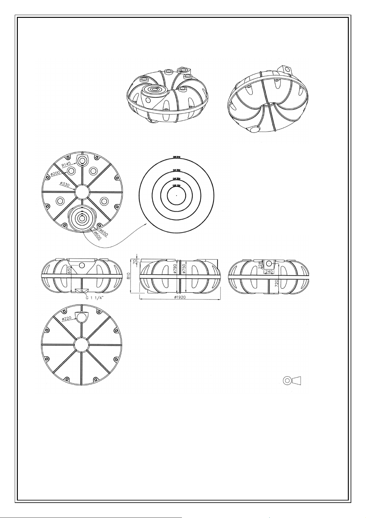
4. Hauptabmessungen
4.1 Torus 800
Die Durchmesser der
Bohrungen für die zu den
genormten Rohrdurchmessern
passenden StandardDichtungen befinden sich in
Punkt 5.1.
The bore diameters for the
standard seals that fit the
standardised pipe diameters can
be found in Section 5.1.
Torus SG DOSG0040 25.02.2013 9 / 12
4.2 Torus 1500
Die Durchmesser der
Bohrungen für die zu den
genormten Rohrdurchmessern
passenden StandardDichtungen befinden sich in
Punkt 5.1.
The bore diameters for the
standard seals that fit the
standardised pipe diameters
can be found in Section 5.1.
Torus SG DOSG0040 25.02.2013 10 / 12

5. Zubehör / Accessories
5.1 Dichtungen / Seals
Die abgebildeten Lamellendichtungen für Rohranschlüsse sind als Standard-Zubehör
erhältlich und - je nach Ausstattungsvariante- im Lieferumfang enthalten.
The lamella seals pictured for the pipe connections are available as standard accessories
and, depending on the variant, are included in the scope of delivery.
*
Durchmesser der Bohrung im Behälter/Tank
Diameters of the bore holes in the container/tank
Torus SG DOSG0040 25.02.2013 11 / 12

5.2 Profi-Tankdom DN 300 / DN 300 Professional Tank Dome
- höhenverstellbar durch Schieben, kann durch Sägen gekürzt werden. Tipp: der Profi-
Tankdom sollte nicht mehr als 50 mm in den Behälter hineinragen, um das Volumen
optimal zu nutzen
- Verlängerung möglich durch KG Rohre DN 300
- PKW-befahrbar
- geliefert mit eigener
technischer Dokumentation
- Height-adjustable, can be
shortened by sawing. Tip: In
order to use the volume in an
optimal way, the Professional
Shaft Extension should not
extend more than 50 mm into
the container.
- Can be expanded using DN
300 underground sewer pipes.
- Car driveable
- Delivered with its own
technical documentation
5.3 Kontrollschacht DN 200 / DN 200 Inspection chamber
- höhenverstellbar durch Schieben, kann durch Sägen gekürzt werden. Tipp: der
Kontrollschacht DN 200 sollte nicht mehr als 50 mm in den Behälter hineinragen, um
das Volumen optimal zu nutzen
- Verlängerung möglich durch KG Rohre DN 200
- geeignet für Belastungen durch Radfahrer oder Fußgänger.
- Height-adjustable, can be shortened by sawing. Tip: In
order to use the volume in an optimal way, the
Inspection chamber should not extend more than
50 mm into the container.
- Can be expanded using DN 200 underground sewer
pipes.
- Suitable for weight to cyclists or pedestrians.
Technische Änderungen und Rechte vorbehalten. Keine Haftung für Druckfehler
Die Inhalte der technischen Dokumentation sind Bestandteil der Garantiebedingungen.
Es sind bei Planung und Einbau die einschlägigen Normen und andere Regelwerke sowie die Unfallverhütungsvorschriften zu
REWATEC reserves the right to make technical changes to this documentation. All rights reserved. REWATEC is not liable for
The contents of the technical documentation are part of the warranty conditions.
All applicable standards and other guidelines as well as the accident prevention regulations must be observed in the planning
REWATEC GmbH Februar 2013
beachten.
printing errors.
and installation of the product.
Torus SG DOSG0040 25.02.2013 12 / 12
 Loading...