

Revolution Technology CB161270 Y, CB121255 X, CB121255 W, CB100836 W, CB100836 X Operation Manual
...
Thank you for purchasing Revolution Technology make blower.
Please read this operation manual carefully before
installing and using the blower, and always keep the
manual where it is readily accessible.
1.Precautions ..............................................
Page 1
2.Checking the Package Contents
.............. Page 1
3.Connection Diagrams ............................. Page 2
4.Installation ................................................Page 2
5.Overheat Protection .................................Page 3
CONTENTS:
1. Precautions
1.1 Precautions for Installation
Do not use in a place where there is flammable gas and / or corrosive gas. Connect the ground wire
to the ground terminal inside the terminal box (if connected).
When installing the blower into your equipment, ensure that the motor lead wires are fixed and do
not move.
In addition, do not apply any pressure to these lead wires.
Installation must be performed by a qualified installer.
1.2 Precautions for Operation
Always turn off power to thermally protected blower before conducting checks or performing work
on the blower.
These types of blowers will restart automatically when blower temperature falls below a certain level.
0
The enclosure temperature of this blower can exceed 70C (depending on operating conditions.).
In case blower is accessible during operation, please attach the following warning label so that it
is clearly visible.
Do not touch the blower blades (impeller) when the blower is in operation.
2. Checking the P
ackage Contents.
2.1 Checking the contents
Please make sure that the package contains all of the items listed below.
Blower ............................................................... 1 piece
Capacitor ........................................................... 1 piece (for single phase only )
2.2 Checking the model name
This manual covers the products specified below.
Please make sure that the model, voltage, are as you ordered by the nameplate.
CB161270 W, CB161270 X, CB161270 Y, CB 161270 Z
CB121255 W, CB121255 X, CB121255 Y, CB 121255 Z
CB100836 W, CB100836 X, Cb100836 Y, CB 100836 Z
Warning Label
TM
AC Centrifugal Blowers
OPERATION MANUAL

Install the blower and capacitor in locations that meet the following conditions.
Indoors (the product is designed and manufactured to be mounted in a machine)
0
0
Ambient temperature -10C ~ +50C
Ambient humidity 0 ~ 85 % (Non-condensing)
No explosive, flammable, and / or corrosive gas.
No exposure to direct sunlight.
No splashing of water or exposure to dust or debris.
No oil or grease, organic solvents, acid or alkaline chemicals.
No continuous vibration or excessive shock.
4. Installation
Wiring Diagram
TM
Contact Us @ +91 7769827676, 9637419123, +91 20 24699118, 65237108, 64700160.
TM
www.fhpgearedmotors.com
Red
White
Black
Black
Short Black wires and connect the capacitor
Wiring diagram for Single Phase Blower
Red-2
Black-2
Red-1
Black-1
~
Ensure that the impeller is rotation in anti clockwise direction, air flow is maximum.
as shown.
To change the direction, connect the supply
wire from White to Red.
Red wires are for running winding and
Black wires for Starting winding.
To change the direction, interchange
Black wires or Red wires.
Wiring diagram for Three Phase Motors
Standard Single Phase Blower
SR Type Single Phase Blower
~
Star Connection
Delta Connection
U
Brown
V
Red
W
Yellow
Black
Blue
White
Blue
Red
U
White
Brown
V
Yellow
Black
W
For the Voltage 415 VAC, 3-Phase Supply, Wires
are connected as shown in the fig.
Short Blue, Black and White and then insulate it
carefully.
To change the direction, interchange any two wires
between U, V & W.
For the Voltage 230 VAC, 3-Phase Supply, Wires
are connected as shown in the fig.
Short Blue & Red, Black & Yellow, and White& Red
as per the fig. Shown.
To change the direction, interchange any two wires
between U, V & W.
CB series blower is equipped with one of two methods to prevent burning the blower as a result of abnormal heating
Impedence Protection ( CB 100836)
The blowers are designed with higher impedence in the motor windings so that even if the motor locks, the increase
in current is kept down hence the temperature does not rise beyond certain constant level.
Thermal protection (CB121255, Cb161270, )
When the blower reaches a predetermined temperature, the internal thermal protector is activated and the blower
is stopped.
With the automatic resume feature, the blower automatically begins operation again as soon as the blower
temperature falls to a certain level. Always turn the power off before performing inspections.
0
0
0
0
Operating temperature of thermal protectors : Open : 120C 5C , Close : 77C
15C
5. Overheat P
rotection
www.fhpgearedmotors.com
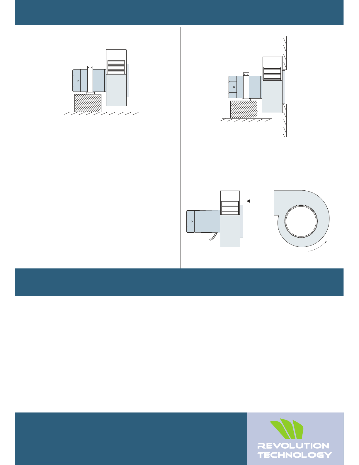
A mounting bracket matching the diameter of the
motor casing is available. With this mounting
bracket, a blower can be secured to the equipment
by using the motor casing section of the blower.
While installing a blower, be sure to use a spacer so
that the impeller casing does not touch the surface to which
the mounting bracket is secured.
4.1 Mounting the blower
Use of mounting bracket (Option)
Air flow Direcion
Mounting on a Plate
4. 2 Mounting the capacitor
(For only single-phase types)
Before mounting the capacitor, check the
capacitance of the capacitor provided, matches the
capacitance indicated on the blower’s nameplate.
Use clamp to mount the capacitor
Air flow
Rotation
Plate
Note : Install the capacitor at least 10cm, away from
the motor as the capacitor life span may be shorten
due to heat from the blower.
Inlet
Specifications subject to change without notice.
+
-
+
-
TM
 Loading...