

Page 1
Copyright Protected Material 2009. All rights reserved.
R/Evolution and the R/Evolution logo are trademarks of Dot Hill
Systems Corp. All other trademarks and registered trademarks
are proprietary to their respective owners.
The material in this document is for information only and is subject
to change without notice. While reasonable efforts have been
made in the preparation of this document to assure its accuracy,
changes in the product design can be made without reservation
and without notification to its users.
Dot Hill assumes that the person using these instructions
is qualified in the servicing and installation of storage
products.
Before you begin
• Verify that the installation site meets the enclosure’s
requirement for:
• Space and airflow
• Temperature
•Power
For detailed information regarding installation
requirements, see 2522/2532 information within the
web-posted R/Evolution 2002 Series Setup Guide
(setup guide hereafter).
• Considering your system configuration and weight
distribution in the rack or cabinet, determine where you
will install each enclosure within the rack or cabinet.
• Confirm that you have cables of appropriate type and
length (described herein) to connect to hosts and to
power outlets.
CAUTION: Two people are needed to lift and move
the enclosure. Use care to avoid injury.
CAUTION: Electrostatic discharge can damage
sensitive components. Be sure you are properly
grounded before touching a static-sensitive
component or assembly.
Required tools
• #2 Phillips screwdriver
• Standard screwdriver
• Antistatic protection devices
Controller/drive enclosure installation
hardware
• Controller enclosure
• Controller enclosure ear caps (2 per enclosure)
• Drive enclosure(s)
• Micro-DB9 serial cable (1 per controller module)
• Ethernet cables (1 per controller; not included)
• Power cords (2 per enclosure)
• SAS cables (1 per expansion module)
IMPORTANT: Before installing, see the “Installation
Checklist” in the web-posted setup guide.
1. Install and secure enclosures into
the rack
Use the R/Evolution Rackmount Bracket Kit Installation
instructions provided with your rail kit when installing and
securing enclosures into the rack.
2. Install hardware options
Install any additional disk drives and options. Refer to the
installation instructions provided with your option.
3. Cabling
Common cabling configurations address hosts, switches,
controller modules (featuring Serial-attached SCSI (SAS)
host interface protocol
), and expansion modules.
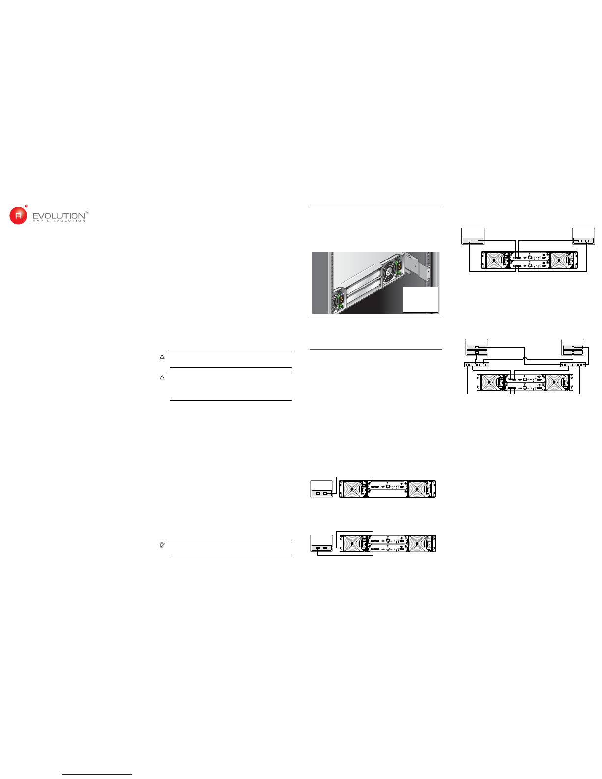
Direct connection
The 2522 and 2532 each support four server connections,
two per controller. Fault tolerance and performance
requirements determine whether to optimize the
configuration for high availability or high performance
when cabling.
Connect the appropriate cable type from the host ports on
each controller to the corresponding HBA on each server.
Several examples follow.
One server/single path
Cable required: 1 - Serial-attached SCSI (Mini-SAS 4x)
One server/dual path
Cables required: 2 - Serial-attached SCSI (Mini-SAS 4x)
Two servers/dual path
Cables required: 4 - Serial-attached SCSI (Mini-SAS 4x)
Switch connection
The 2522 and 2532 support four switch connections, two
per controller. Connect SAS cables from controller host
ports to switch ports, and from switch ports to hosts. See
the web-posted setup guide for details.
Two servers/two switches
Cables required: 8 - Serial-attached SCSI (Mini-SAS 4x)
Connecting remote management hosts
The management host directly manages systems
out-of-band over an Ethernet network:
1. Connect an Ethernet cable to the network port on each
controller.
2. Connect the other end of each Ethernet cable to a
network accessible by your management host
(preferably on the same subnet).
Drive enclosure cable requirements
Follow the guidelines and cabling table below when
installing SAS cables connecting controller and drive
enclosures:
• Use R/Evolution or OEM-qualified SAS 4x cables with
3Gb connectors to connect a controller enclosure to
drive enclosures as specified below:
• Up to three 2122s per 2522/2532
• Up to six 2130s per 2522
• Up to seven 2130s per 2532
• You may need to order additional or longer cables if you
are cabling a fault-tolerant configuration.
• Reverse cabling ensures the highest level of fault
tolerance, enabling controllers to access remaining
drive enclosures, if a drive enclosure fails.
Rear panel
rack mounted
component
locator view
Server
0A
Server
0A
0B
Server
Server
0A
0B
Server
Server
0A
0B
SWA
SWB
2522/2532 Installation
PRELIMINAR
Y
© <Copyright>
Revision A edition August 2009
Product names mentioned herein may be trademarks of their
respective companies as reflected by an associated footnote. The
information in this document is subject to change without notice.
Printed in <the US>.
P/N: 83-00004525-11
Revision A
August 2009
Page 2
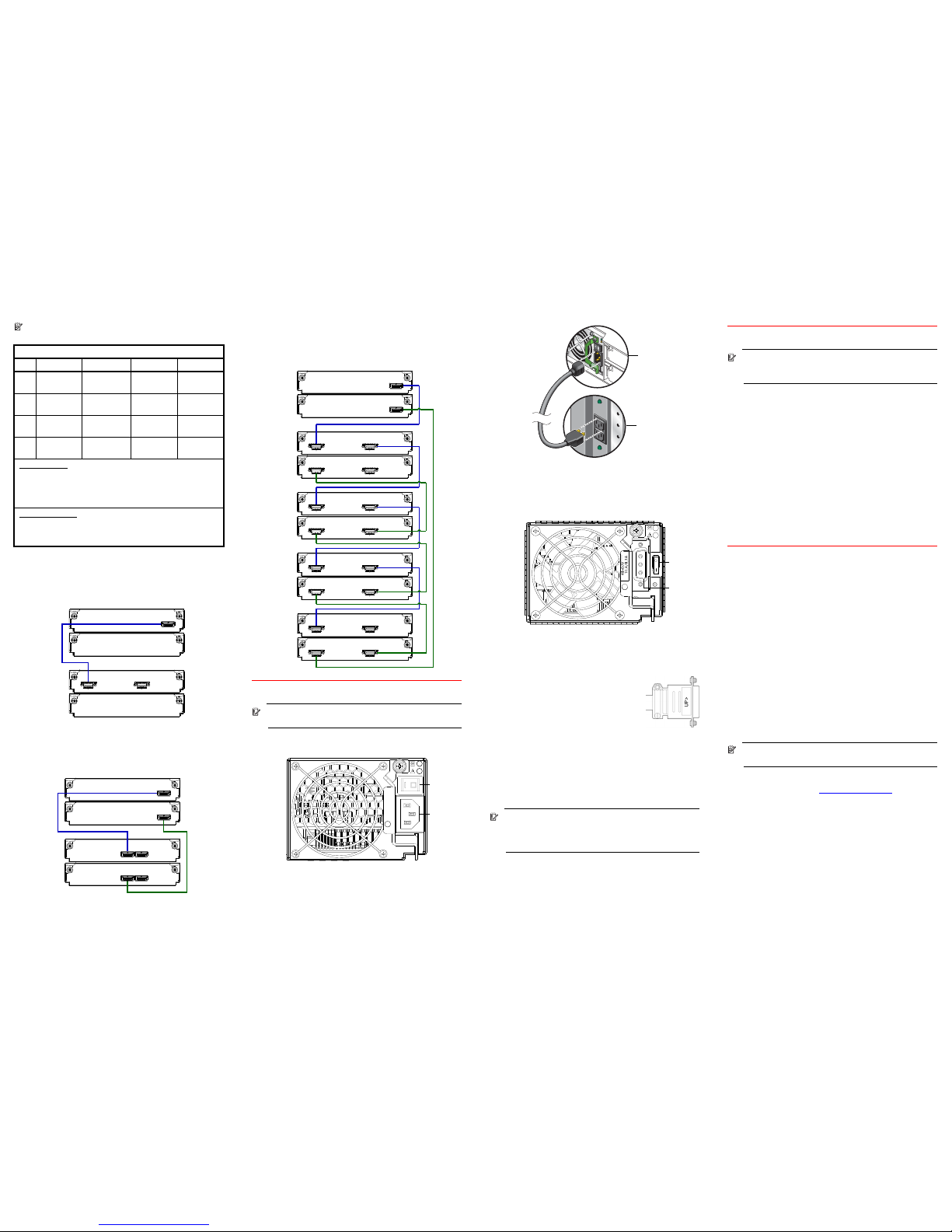
NOTE: Cabling diagrams use simplified graphics
and reference the table below.
2522 or 2532 single-controller enclosure
and one 2130 drive enclosure
Cable required: 1 per table above
2522 or 2532 dual-controller enclosure and
one 2122 drive enclosure
Cables required: 2 per table above
2522 or 2532 dual-controller enclosure and
multiple 2130 drive enclosures
Cables required: 8 per table at left
4. Power cords
IMPORTANT: See “Electrical Requirements” in the
web-posted setup guide for additional information.
AC models
1. Turn off all power switches.
2. Using the provided AC power cords, connect each
power supply module to one power source in the rack.
3. Connect the primary power cords from the rack to
separate external power sources.
DC models
1. Before making any DC connections, shut off the main
circuit breaker in the rack.
2. Turn off all enclosure power switches.
3. Connect a DC power cable to each
power supply using the D-shell
connector. Use the up arrow on the
connector shell to ensure proper
positioning.
4. Tighten the screws at the top and
bottom of the shell, applying a torque between 1.7 N-m
(15 lb-in) and 2.3 N-m (20 lb-in), to securely attach the
cable to the DC power supply module.
5. To complete each required DC connection, secure the
other end of each DC power cable to the target DC
power source.
IMPORTANT: Check the DC cable labels before
connecting each cable to its power source. One wire
is labeled ground; the other two are labeled positive
and negative.
6. Turn on the main circuit breaker to the rack.
5. Powering up
IMPORTANT: When powering up, make sure to
power up the enclosures and servers in proper
sequence.
Power up sequence:
• Drive enclosure(s) first;
• Controller enclosure(s) next;
• Switches (if applicable), followed by servers (if they are
powered down for maintenance).
To power on the storage system:
1. Press the power switches on the back of each drive
enclosure to the On position. Wait several minutes to
ensure that all drives have had time to spin up, so that
they can be recognized by the controller.
2. Press the power switches on the back of the controller
enclosure to the On position.
6. Next steps
Perform the following steps to finish the installation and
configure/provision the storage system:
1. Complete the hardware installation.
For additional hardware installation information, see the
web-posted setup guide.
2. Use the storage system’s web-based management
interface, RAIDar, to configure and provision the
system.
For information about accessing and using RAIDar, see
the “Getting Started” section in the web-posted
R/Evolution 2002 Series RAIDar User Guide. To sign in
to RAIDar, use the default user name manage and
password !manage.
After signing in to RAIDar, you can use its online help
as an alternative to consulting the user guide.
NOTE: For a complete list of related documentation,
see the “Preface” in the web-posted setup guide.
See Dot Hill’s customer resource center (CRC) web site
for additional information crc.dothill.com
. Select
R/Evolution Products and go to R/Evolution 2002 Series.
SAS Cable Requirements
Item 2522 2532 2122 2130
2522 N/A N/A mini-SAS to
mini-SAS
mini-SAS to
SAS
2532 N/A N/A mini-SAS to
mini-SAS
mini-SAS to
SAS
2122 mini-SAS to
mini-SAS
mini-SAS to
mini-SAS
mini-SAS to
mini-SAS
mini-SAS to
SAS
2130 mini-SAS to
SAS
mini-SAS to
SAS
mini-SAS to
SAS
SAS to SAS
Product Models
:
2522 - Small form factor 24-drive controller enclosure (2.5”)
2532 - Large form factor 12-drive controller enclosure (3.5”)
2122 - Small form factor 24-drive enclosure (expansion)
2130 - Large form factor 12-drive enclosure (expansion)
Cable Designators
:
Mini-SAS to mini-SAS denotes SFF-8088 to SFF-8088
Mini-SAS to SAS denotes SFF-8088 to 8470
SAS to SAS denotes 8470 to 8470
Controller A
0A
1A
Drive
enclosure
1
Controller
enclosure
0
In
Out
Controller A
Controller B
Controller
enclosure
0
In
Out
0A
0B
Drive
enclosure
1
1A
1B
In
Out
2A
2B
3A
3B
4A
4B
0A
0B
1A
1B
Drive
enclosure
2
Controller
enclosure
0
Drive
enclosure
1
In
Out
In
Out
Out
Out
Drive
enclosure
3
Drive
enclosure
4
Controller A
Controller B
In
Out
In
Out
In
In
Out
Out
In
In
AC
model
PSU
Power
switch
Power
cord
connect
Powe r su pply
module
Rack power
source
DC
model
PSU
Power
switch
Power
cable
connect
 Loading...