

Revolabs xTag 02-DSKSYS-D, xTag 04-DSKSYSEU-D Installation And Operation Installation And Operation Manual
Page 1
1
x T a g ™ M a n u a l 0 2 - D S K M A N - D P P - 1 1
M f g P a r t # 9 1 - 8 6 0 1 - 5 0 N 0 0 J u l y 2 0 0 7 ( R e v 1 . 3 )
Note: Microphones must be fully charged
and paired to the Charger Base
prior to first use.
IIIInstallation and Operation
nstallation and Operation nstallation and Operation
nstallation and Operation
Guide
GuideGuide
Guide
xTag™
Wireless Microphone System
Models 02-DSKSYS-D, 04-DSKSYSEU-D
Revolabs, Inc.
Revolabs, Inc.Revolabs, Inc.
Revolabs, Inc.
Page 2

22
System Specifications
Dimensions, (L, W, H) and Weight
Desktop Charger Base
3.9” (10 cm) x 2.4” (6 cm) x 1.0” (2.56 cm), 0.5 lb (0.23 kg)
Wireless Microphone
0.9” (2.4 cm) x 0.8” (1.95 cm) x 2.6” (6.68 cm), 0.05 lb (0.02 kg)
Shipping Weight 1.5 lbs (0.68 kg)
Radio Frequency
02-DSKSYS-D 1.92 to 1.93 GHz (UPCS North America)
04-DSKSYSEU-D 1.88 to 1.90 GHz (DECT EU)
Connectors
Desktop Charger Base
Mini USB – 5 pin connector, USB 2.0
Wireless Microphone
Power – proprietary 4 pin connector
Audio – 2.5mm mono audio
Microphone patterns Unidirectional – cardioid.
Battery Lithium Polymer, up to 8 hours talk time
Charge Time 2.0 hours approx.
Range 65’ (20 meters) approx. (no obstructions)
Audio Bandwidth 100-8000 Hz
Encryption 128-bit DSAA authentication (DECT
Standard Authentication Algorithm)
Environmental Requirements
Temperature 40° to 105° F (5° to 40° C) operating
Humidity 20% to 85%
Page 3

21
Warranty
WarrantyWarranty
Warranty
Revolabs, Inc. warrants this product to be free of manufacturing
defects. Repair or replacement of any defective part or unit (at the
discretion of the Seller) will be free of charge for the period of 90
days.
Any attempt by the user to alter the equipment, or equipment
damaged by negligence, accident, or Acts of God voids this
warranty.
The Seller shall not be liable for any consequential damage
resulting from the malfunction of this product. Should the user
experience unsatisfactory performance from this equipment,
contact the Seller to obtain instructions for return, or replacement,
as deemed necessary.
This warranty is not transferable by the original end user.
Revolabs, Inc.
63 Great Road
Maynard, MA 01754
www.revolabs.com
1-800-326-1088
© 2007 REVOLABS, INC. All rights reserved. No part of this
document may be reproduced in any form or by any means
without express written permission from Revolabs, Inc.
Product specifications are subject to change without notice.
x T a g ™ M a n u a l 0 2 - D S K M A N - D P P - 1 1
M f g P a r t # 9 1 - 8 6 0 1 - 5 0 N 0 0 J u l y 2 0 0 7 ( R e v 1 . 3 )
Page 4

20
LED Status Indications
The following LED patterns are shown on either the Microphone or
the Charger Base.
LED pattern Meaning
Solid GREEN
(Microphone only)
Confirmation of power-up or battery
reaching full charge.
Solid RED Pairing mode, or confirmation of
powering-down, or battery charging.
GREEN flash every
1.5 seconds
Microphone connected and un-muted.
Two RED flashes
every 1.5 seconds
Microphone connected and muted.
YELLOW flash
alternating with either
GREEN or two RED
flashes
Microphone connected, battery low.
Alternating RED,
YELLOW, GREEN,
YELLOW (Microphone
only)
Searching for a connection, or out of radio
range. The Microphone will try to reestablish the link for about 15 minutes,
and then turn off automatically. The
Microphone will beep five times every 30
seconds as a reminder to bring the
Microphone closer to the Charger Base.
Alternating RED,
YELLOW, GREEN,
YELLOW
May also indicate that microphone is not
paired.
Rapid RED flashes
continuing for more
than a few seconds
Radio congestion – it is not possible to
make a radio connection because there
are already too many nearby users of
the UPCS band, or there is heavy radio
interference. Other UPCS users will
include some types of digital cordless
phones, and other installations.
Groups of five rapid
RED flashes
Unit is faulty. Please contact your place
of purchase for advice on return.
Page 5

19
System Functions
System FunctionsSystem Functions
System Functions
The following table shows the functions supported by
the xTag ™ System:
System Functions
Charger
Base
LED Status
Wireless
Microphone
LED Status
Action
To Pair the Microphone and Base
Off Off
Press the Microphone MUTE button for
about 8 seconds (LED solid RED), and
then press the MUTE button on the
Charger Base for about 8 seconds
(LED solid RED).
To Mute / Un-mute the
xTag ™ Microphone
On On
A short press of the Microphone MUTE
button or Charger Base MUTE button
causes flashing RED LED on each unit
indicating that the Microphone has
audio muted. Pressing either MUTE
button again will un-mute Microphone
(flashing GREEN LED on each unit).
To Turn Off Microphone
On On
Press and hold the Microphone MUTE
button for about 10 seconds, until the
LED stays solid RED, and then
release.
Or
Dock the Microphone into the Charge
Base for less than 2 seconds.
To Turn On Microphone
Off Off
Press and hold the Microphone MUTE
button for about 3 seconds, until the
LED shows solid GREEN.
Or
Dock the Microphone into the Charge
Base for at least 4 seconds.
v
Table of Contents
Safety and General Information ..................................................... 1
Introduction .................................................................................... 4
System Components ..................................................................... 5
Revolabs xTag ™ Charger Base ................................................... 5
Mute Button ............................................................................... 5
USB Connection ........................................................................ 6
Installing the xTag ™ USB System ............................................... 6
Computer Software Set-up ........................................................ 6
xTag ™ Wireless Microphone ..................................................... 11
Using the xTag ™ Microphone ................................................ 11
Adjusting the Volume .............................................................. 13
Charging the Batteries ............................................................. 14
When to Charge ...................................................................... 14
Setting the Broadcast Power Level ......................................... 16
Pairing the Microphone to the Charger Base .......................... 17
System Functions ........................................................................ 19
LED Status Indications ................................................................ 20
Warranty ...................................................................................... 21
System Specifications .................................................................. 22
Page 6

1
Safety and General Information
This section contains important information regarding
safe and efficient xTag ™ operation, and declarations
of required certification / regulation compliance.
Please read this information prior to using your
xTag™.
FCC User Information
FCC Registration Number: 0014898290
FCC ID Number: T5V02DSKSYS Revolabs Charger
FCC ID Number: T5V01EXEMIC Revolabs Microphone
FCC Notice to Users
Users are not permitted to make changes or modify the equipment in any
way. Changes or modifications not expressly approved by Revolabs, Inc.
could void the user’s authority to operate the equipment.
This device complies with Part 15 of the FCC Rules. Operation is subject
to the following two conditions: (1) this device may not cause harmful
interference, and (2) this device must accept any interference received,
including interference that may cause undesired operation.
Federal Communications Commission (FCC)
Radiation Exposure Statement
Important: This equipment complies with FCC radiation exposure limits
set forth for an uncontrolled environment.
Industry Canada Notice to Users
Operation is subject to the following two conditions: (1) This device may
not cause interference and (2) This device must accept any interference,
including interference that may cause undesired operation of the device
Ref IC: RSS 210 Sec. 5.11. The term “IC:” before the
certification/registration number only signifies that registration was
performed based on a Declaration of Conformity indicating that Industry
Canada technical specifications were met. It does not imply that Industry
Canada approved the equipment. See Ref IC Self-Marking 6(f) and RSP100 Sec. 4.
IC ID Number: 6455A-02DSKSYS Revolabs Charger
IC ID Number: 6455A-01EXEMIC Revolabs Microphone
18
Note: The LED will be solid RED until pairing is
confirmed, as indicated by a short green LED flash,
followed by flashing RED on both the Microphone
and the Charger Base. If pairing fails on either unit,
the LED will flash alternately GREEN and RED for a
few seconds. If this happens, repeat these steps.
Page 7

17
Pairing the Microphone to the Charger Base
“Pairing” creates an encrypted association between the
Wireless Microphone and the Charger Base with a
unique electronic serial number. Once the Microphone
and Charger Base have been paired, the Microphone
will automatically try to connect to the Charger Base
whenever it is lifted from the Charger Base.
Remember, the Microphone is always muted (flashing
RED LED) when it is first removed from the Charger
Base and the Mute button needs to be pressed to
activate the Microphone, as indicated by a flashing
green LED.
Note: The Microphone in new systems will need to be
manually “paired” prior to first use.
If a Microphone is lifted from the Charger Base and the
Microphone LED slowly flashes alternating RED and
GREEN for 10 seconds, it means that the Microphone
needs to be paired to the system.
To pair the Microphone to the Charger Base:
1. Make sure the Microphone is turned OFF (no LED
activity). If the unit is ON, press and hold the MUTE
button for 10 seconds until the LED turns solid
RED. Alternately, place the Microphone in the
Charger Base for less than 2 seconds.
2. Enable the pairing mode by holding the
Microphone’s Mute button down for eight seconds.
The LED will turn solid GREEN and then solid
RED. Release the Mute button. The Microphone
unit is now in pairing mode.
3. Within 5 seconds of releasing the Microphone’s
Mute button, push and hold the Charger Base’s
Mute button for eight seconds to enter into pairing
mode.
2
Restricted use with certain medical devices
Hearing Aids
Some devices may interfere with some hearing aids. In the event of such
interference, you may want to consult with your hearing aid manufacturer
to discuss alternatives.
Other Medical Devices
If you use any other personal medical device, consult the manufacturer of
your device to determine if it is adequately shielded from RF energy. Your
physician may be able to assist you in obtaining this information.
Export Law Assurances
This product is controlled under the export regulations of the United States
of America and Canada. The Governments of the United States of
America and Canada may restrict the exportation or re-exportation of this
product to certain destinations.
For further information contact the U.S. Department of Commerce or the
Canadian Department of Foreign Affairs and International Trade. The use
of wireless devices and their accessories may be prohibited or restricted in
certain areas. Always obey the laws and regulations on the use of these
products.
02-DSKSYS North America UPCS Usage Restriction
Due to the UPCS frequencies used, this product is licensed for operation
only in the United States of America and Canada.
04-DSKSYSEU European Union Usage Restriction
Due to the frequencies used, this product is licensed for operation only in
the European Union countries.
Page 8

3
European Compliance
This equipment has been approved in accordance with Council Directive
1999/5/EC “Radio Equipment and telecommunications Equipment.”
Conformity of the Equipment with the guidelines below is attested by the
CE mark.
Model Numbers:
04-DSKCHGEU-D Revolabs xTag™ Charger
04-DSKMIEU-D Revolabs xTag Microphone
Standards to which Conformity is declared:
RF ETSI EN 301 406 V 1.4.1 03/2001
EMC ETSI EN 301 489-6 v1.2.1 (2002-04)
WEEE Notification:
The Waste Electrical and Electronic Equipment (WEEE) directive
(2002/96/EC) is intended to promote recycling of electrical and
electronic equipment and their components at end of life.
16
Setting the Broadcast Power Level
In confined settings where for multiple system
installations are required, or where audio interference
is likely, it may be necessary to reduce the broaccast
power levels.
The broadcast power level between the xTag ™
Microphone and Charger Base can be set to the
following three levels.
• Highest power level – 60 feet (25M) maximum
operating distance between Microphone and Base
(default setting).
• Medium power level – 20 feet (7M) maximum
operating distance between Microphone and Base.
• Lowest power level – 6 feet (2M) maximum
operating distance between Microphone and Base.
To set the broadcast power level:
Press and hold the Mute button while plugging the
USB cable into the Charger Base.
The status LED on the charger will display a sequence
of flashes, during which it will flash once, then twice,
then three times, where:
1 flash = full power
2 flashes = medium power
3 flashes = low power.
This cycle will repeat 10 times. During any of the
cycles, simply release the Mute button immediately
after the desired power indication, to set the xTag ™
broadcast/receive power.
Page 9

15
regarding battery replacement and proper disposal
procedures. Warning: Exposing the batteries to fire
may result in an explosion.
4
Introduction
IntroductionIntroduction
Introduction
Congratulations on the purchase of your Revolabs
xTag ™ USB wireless communication system! This
wireless system provides high band-width audio from a
compact wireless microphone enabling reliable, secure,
and un-tethered personal communication.
The xTag ™ Wireless Microphone System is a unique
marriage of innovative technology and ergonomic
stylish design, featuring 1.9 GHz DECT technology.
This product enhances audio communication in both
personal and enterprise applications, using Multi-
Carrier, Time Division Multiple Access and Time
Division Duplex (MC/TDMA/TDD) radio transmissions
both to and from the microphone.
This means that the system:
• Can co-exist with other wireless products such as
wireless LANs (802.11 B&G) and cellular phones,
• Eliminates the unwanted noise that these devices
can cause.
Note: It is recommended that no more than 3 xTag ™
Systems be used in the same room.
Page 10

5
System Components
System ComponentsSystem Components
System Components
Your Revolabs xTag ™ System package contains:
• Compact Charger Base
• Wearable xTag ™ wireless microphone
• Earpiece with volume control
• Quick release lanyard and a USB cable
• Installation and Operation Guide
• xTag ™ Quick Start Guides
Revolabs
RevolabsRevolabs
Revolabs
xTag
xTagxTag
xTag
™™™™ Charger Base
Charger Base Charger Base
Charger Base
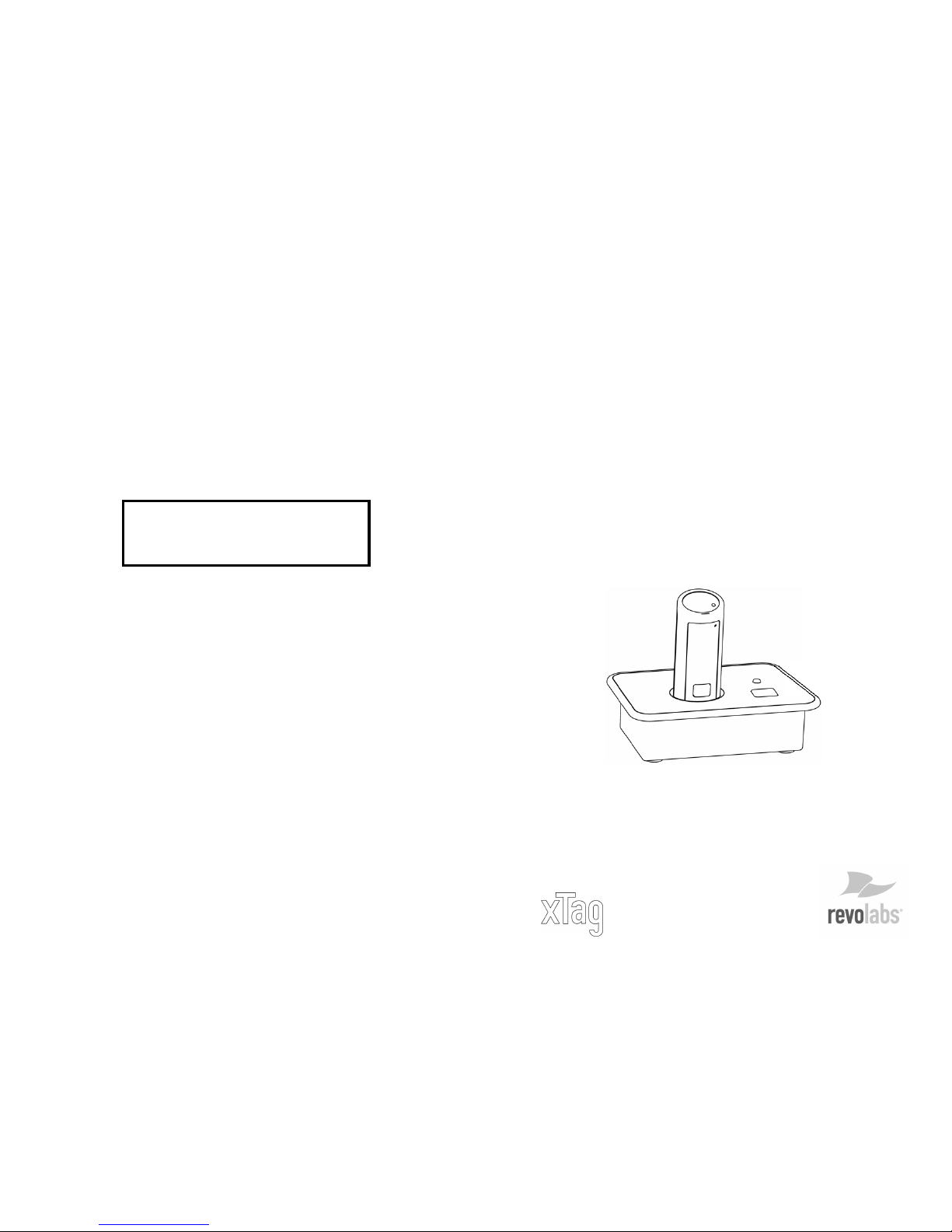
Use the Charger Base to store and charge the
Microphone when not in use. The Microphone must be
properly inserted into the base and seated flush for
charging to occur.
1. Charger Bay — charges Microphone
2. LED indicator — mute and pairing status indicator
3. MUTE button — duplicates the Microphone mute function
4. Mini USB connector — computer audio and power connection
Mute Button
Pressing the MUTE button toggles between muting
(flashing RED LED status) and un-muting (flashing
GREEN LED status) on the Wireless Microphone.
2
3
1
4
14
Charging the Batteries
To charge the batteries:
Place the Microphone into the xTag ™ Charger Base.
Note: The unit will only work on a powered USB port
that can supply 500mA (found on most computers and
laptops). It will not work with un-powered hubs (no AC
adapter to power the hub).
During charging, the Microphone status LED indicator
changes from solid RED to solid GREEN as charging
completes. The Charger Base status indicator remains
off during charging. The Microphone is always muted
while in the Charger Base. The battery charges from
fully depleted to fully charged in approximately two
hours, however, it can be “quick-charged” to 80%
capacity in 45 minutes.
Note: A fully charged battery provides approximately 8
hours of talk time.
When to Charge
Before using the Microphone for the first time, charge
for 8 hours or overnight in the Charger Base (until
microphone LED turns solid GREEN).
Recharging
RechargingRecharging
Recharging
When the Microphone LED begins flashing alternating
YELLOW and RED or YELLOW and GREEN, the
battery needs recharging. Over time (years), batteries
gradually wear down and require charging after a
shorter period of use. This is normal.
Important: The Lithium Polymer rechargeable battery
that powers the xTag ™ Microphone is not user
serviceable. Please see the Revolabs Knowledge Base
website area (
www.revolabs.com
) for information
Page 11

13
Adjusting the Volume
The volume of the Microphone is set at the factory and
cannot be adjusted on the Wireless Microphone. It may
be possible to change the volume on computer or IP
calls by adjusting the software control parameters (see
Computer Software Settings, below).
Note: Moving the Microphone closer to the mouth will
increase the volume.
To change the volume on the earpiece, use the dial on
the earpiece wire. Turning the dial towards the
earpiece will increase the volume, and turning the dial
towards the Microphone will decrease the volume.
6
Note: Pressing the MUTE button on a Microphone will
similarly toggle between mute and un-mute and display
on both status LEDs.
USB Connection
Use the supplied cable to connect the mini USB
connector to the Charger Base and the standard end
to your computer USB port.
Your computer will alert you that it has found new
hardware, and the Revolabs xTag ™ operating software
will automatically load. See the user settings specified
below for adjusting the audio connections to your
liking.
Installing the
Installing the Installing the
Installing the
xTag
xTagxTag
xTag
™™™™ USB
USBUSB
USB System
SystemSystem
System
The xTag ™ USB system is easily installed in the home
or office. Simply follow the instructions below to attach
the unit to your equipment.
Computer Software Set-up
Use the supplied USB cable to connect the mini USB
connector to the Charger Base and the standard end
to your computer USB port. Your computer will alert
Page 12

7
you that it has found new hardware, and the Revolabs
xTag ™ operating software will automatically load.
It is possible to configure your computer settings to
playback audio through the earpiece attached to the
Wearable microphone (default settings) or through the
computer speakers (internal or desktop).
The following examples use the Windows XP Operating
System Classic settings. You may notice slight
differences in appearance when using other Windows
operating systems.
To modify the default microphone earpiece audio
output settings:
1. At the lower-right of your screen, click the Start
button.
2. Select Settings and Control Panel.
3. Click the Sounds and Audio Devices icon.
12
2. Attach the Microphone to your person, as close to
the mouth as possible (within 6 - 12 inches is
optimal).
3. With the Microphone positioned, un-mute the
Microphone by pressing and releasing the Mute
button.
The flashing green LEDs on the Microphone and
Charger Base confirm that the Microphone is now
active.
To Turn off the Microphone:
Return the Microphone to the Charger Base. The
Microphone LED will show a 5 second self-test
pattern.
Alternately, turn off the Microphone manually by
pressing and holding the Mute button for
approximately 10 seconds, until the LED turns
solid RED, then release the mute button.
Note: If the Microphone is moved out of range of the
Charger Base (~65 feet, 20M) the connection
between the Charger Base and Microphone will be
dropped and the Microphone will mute (LED flashes
alternating RED, YELLOW and GREEN). If the
microphone is moved back into range within 15
minutes the connection will automatically be reestablished to its original state. If not, the
microphone will turn off after 5 minutes.
Note: The xTag™ microphone is designed to be
used with the xTag™ system only. This microphone
is not compatible with other Revolabs Solo™ Desktop
or Executive systems, nor are Solo-Desktop
microphones compatible with the xTag™ Charger
Base.
Page 13

11
xTag
xTagxTag
xTag
™™™™ Wireless
Wireless Wireless
Wireless Microphone
MicrophoneMicrophone
Microphone
The xTag ™ wireless personal microphone uses
encrypted communication to synchronize with the
Charger Base. The xTag ™ Microphone can be worn on
the user’s shirt pocket, lapel, or on a lanyard, and
provides high quality full duplex audio between the
user and the computer and/or internet phone system.
1. Pocket Clip — attaches microphone to the user
2. LED Indicator — visual status for mute, un-mute, and pairing
3. Mute Button — press to mute, un-mute and pair microphone
4. Earpiece Jack — accepts the 2.5mm plug for the earpiece
5. Charging Port — docks to all battery charger units
Using the xTag ™ Microphone
To operate the xTag ™ microphone:
1. Remove the Microphone from the Charger Base.
The Microphone automatically turns on and mutes,
displaying a flashing red LED when removed from
Charger Base.
The Wireless Microphone has a clip on the back
which allows the Microphone to be easily clipped
onto a shirt pocket, blouse or lapel. The
Microphone can also be clipped on to a lanyard and
be worn around the neck.
3
54 2
1
8
The Sounds and Audio Devices Properties dialog
will display, as shown. The xTag ™ audio codec
software will be selected.
4.
Open the Volume settings for Sound recording to
view the volume levels selected for the
microphone input (Capture) on the computer.
Page 14

9
5.
Make sure that the level for the Microphone is
close to the top (maximum) and that the Mute
box is not checked.
6.
In the Sound playback section, open the
Volume settings for to control the volume you
hear in the Microphone’s earpiece.
Adjust the Speaker level at the master Volume
control if necessary.
7.
At the bottom of the Microphone section, click
the Mute box in the Microphone section to
prevent the Microphone directly feeding back its
own audio to the earpiece (i.e. “sidetone”).
It may be necessary to use the OptionsProperties menu to display the Microphone
volume control.
IP telephony and computer telephony
applications (e.g., Skype) may also offer options
for controlling the audio levels and playback
capabilities. Please consult the application
guide for the software package for additional
instructions.
8. Change the Sound playback Default device to
your regular audio codec (SigmaTelAudio in this
10
example) to playback audio through the internal
or external speakers of the computer instead of
the earpiece.
9. At the bottom of the dialog, click Apply, and
then click OK.
Note: Laptop computers with built-in microphones may
continue to operate even when the xTag software is
running. To prevent the built-in microphone audio
feeding through to the speakers, check the Mute box on
the laptop audio program Input Monitor, as shown
below.
 Loading...