

Page 1
1
REVOLABS FLX™ UC 1000 &
10-FLXUC1000
10-FLXUC1500
REVOLABS FLX™ UC 1500
IP & USB Conference Phone
Installation and Operation Guide
Models:
Page 2

2
© 2017 REVOLABS, INC. All rights reserved. No part of this document may be
reproduced in any form or by any means without express written permission
from Revolabs, Inc. Product specifications are subject to change without notice.
R e v o l a b s F L X U C 1 0 0 0 / F L X U C 1 5 0 0 I n s t a l l a t i o n a n d O p e r a t i o n
G u i d e
10- F L X U C 1500- EN
F e b r u a r y 2017 ( R e v 2 . 7 . 0 )
Page 3
3
Resource
Website
Revolabs
www.revolabs.com
Revolabs FLX UC 1000
www.revolabs.com/uc1000
Revolabs FLX UC 1500
www.revolabs.com/uc1500
Customer Support
www.revolabs.com/support
Online Resources
Safety Warnings
Do not expose any component of the FLX UC 1000 of FLX UC 1500 to
water, moisture, or high humidity.
Do not expose any component to extreme high or low temperatures.
Do not expose any component to lit candles, cigarettes, cigars, or to open
flames, etc.
Do not drop, throw, or try to bend any component, as rough treatment
could damage them.
Do not open the casings of any component
Do not use any other accessories than Revolabs’ originals intended for use
with this product. Use of non-original accessories may result in loss of
performance, damage to the product, fire, electric shock or injury. The
warranty does not cover product failures which have been caused by use
of non-original accessories.
Page 4

4
Contents
Online Resources ............................................................................................ 3
Safety Warnings .............................................................................................. 3
Contents ......................................................................................................... 4
Introduction .................................................................................................... 7
Getting Started ............................................................................................... 8
Content and Component Overview................................................................ 8
Base Unit .................................................................................................. 8
Dialer ........................................................................................................ 9
Setting up the system................................................................................. 12
Connecting the Dialer .............................................................................. 13
Connecting to an IP Network for VoIP Calling ........................................... 13
Connecting to a Computer ....................................................................... 14
Connecting Extension Mics ..................................................................... 15
Using the Cable Clamps .......................................................................... 16
User Interface ............................................................................................... 17
Base Unit ................................................................................................... 17
Dialer ......................................................................................................... 17
Menu Tree ............................................................................................... 18
Home Screen ........................................................................................... 19
Menu Options ......................................................................................... 21
Web User Interface (Web UI) .................................................................... 33
Basic Operations ........................................................................................... 57
SIP phone operations ................................................................................. 57
Dialing a Number .................................................................................... 57
Redialing a Number ................................................................................. 57
Dialing a Contact .................................................................................... 58
Initiating a second call while another call is active ................................... 58
Answering an Incoming Call .................................................................... 58
Ignoring an Incoming Call ....................................................................... 58
Page 5

5
Hanging Up a Call ................................................................................... 58
USB Audio ................................................................................................. 58
Conference USB and SIP Calls ................................................................. 59
Using Do Not Disturb ................................................................................. 60
Configuring the FLX UC 1000 or FLX UC 1500 for your VoIP Network ........... 61
Configuring using the Web User Interface ................................................... 61
Configuring using the Dialer ...................................................................... 61
Configuring using a Provisioning Server, Option 66 .................................... 62
Configuring using a Provisioning Server, Option 150 .................................. 62
Provisioning file .......................................................................................... 63
Sample device configuration file ............................................................... 63
Provisioning file parameters ....................................................................... 65
Advanced Operations .................................................................................... 82
Dial Plan .................................................................................................... 82
Dial Plan Syntax ...................................................................................... 82
Dial Plan Examples ................................................................................. 83
Device Manager ............................................................................................. 84
Installation & Configuration ....................................................................... 84
For Windows operating systems .............................................................. 84
For Macintosh operating systems ............................................................ 85
For Chrome OS ....................................................................................... 85
Upgrading the Device Firmware ..................................................................... 86
Through the Web Interface ......................................................................... 86
From the Provisioning Server ...................................................................... 86
Compliance ................................................................................................... 87
FCC Notice to Users ................................................................................... 87
Radio and Television Interference ............................................................... 87
Industry Canada Notice to Users ................................................................ 89
Notice to European Customers ................................................................... 89
WEEE Notification ...................................................................................... 90
Page 6

6
Environmental Requirements ........................................................................ 90
Appendix ...................................................................................................... 91
Call Control Functionality Details per Third Party Application .................... 91
Using Windows Computers ...................................................................... 91
Using Apple Computers ........................................................................... 91
Known Issues ............................................................................................. 93
Configuring the FLX UC 1000 / 1500 in Windows ...................................... 95
Troubleshooting ......................................................................................... 96
Reboot ..................................................................................................... 96
Restore Factory Defaults ......................................................................... 96
Cannot Access Web User Interface ........................................................... 96
Change language ..................................................................................... 97
USB Audio call Answering and Hang-Up not working .............................. 97
Call Forwarding Behavior ........................................................................ 98
Specific Call Manager Configuration .............................................................. 99
Page 7

7
Introduction
Thank you for choosing a FLX UC 1000 or FLX UC 1500 IP & USB Conference
Phone by Revolabs. This conference phone allows you to communicate via
your call manager and a softphone, messaging, video conferencing, or webinar
application, as well as bridge these calls together. With the FLX UC products,
call performance is built to be of the highest quality to ensure every word of the
conversation is heard.
This document covers the FLX UC 1000 and the FLX UC 1500 as configuration
of these products is similar. Where there is a difference in capabilities or
configuration, the document will highlight that explicitly.
Page 8
8
Getting Started
FLX UC 1000
FLX UC 1500
Base Unit
Base Unit
Dialer
Dialer
Ethernet Cable
Ethernet Cable
USB Cable
USB Cable
Extension Microphones (Qty. 2)
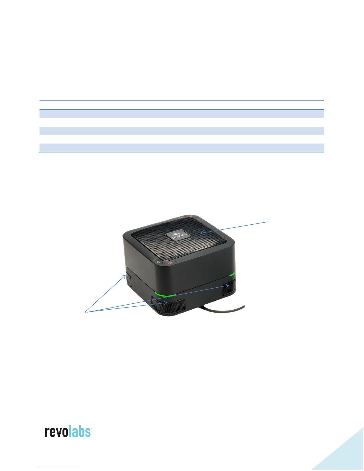
Speaker Elements
Directional
Microphones
Content and Component Overview
Depending on the system you have purchased you will find the following
content in the box:
For setup of the device, remove all the items from packaging.
Base Unit
The base units of the FLX UC 1000 and FLX UC 1500 house the speaker
elements and four embedded microphones. On the top of the device are five
capacitive touch buttons for: volume up, volume down, mute, answer call, and
end call.
On the corners of the base unit, LED lights display the status of the unit.
Three different microphone states correspond to the color of the LEDs.
Page 9
9
Microphone State
LED Color
Active microphones, unmuted
Green
Active Microphones, muted
Red
Microphones not active
Configurable: Amber, Green, or Off
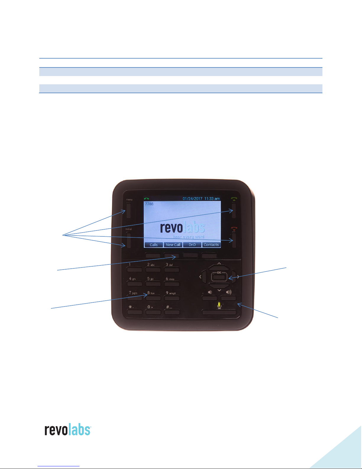
Volume Control &
Mute
Function
Keys
Soft Keys
Keypad
Navigation
& Selection
Buttons
Ports on the bottom of the base unit are used to connect the dialer, the USB
cable, and Ethernet cable for the FLX UC 1000, and additionally two extension
microphones on the FLX UC 1500.
Dialer
The dialer has five categories of buttons:
Function Keys: menu, redial, answer call/new call, hang up
Soft Keys: 4 keys below the color display that correspond to changing
menu options presented on the display
Keypad: entering numbers, letters, and special characters
Navigation: to navigate the menus on the display
Page 10

10
Volume Control and Mute: adjusting the volume and toggling mute
on/off
Function Keys
The Menu button provides access to the main menu for the FLX UC 1000 or
FLX UC 1500. When already in a menu or submenu, pressing the menu
button will return the display to the home screen.
The Redial button will redial the last number used to place an outgoing call.
The Answer Call/New Call Button, labeled with the green phone icon, provides
the ability to answer an incoming call. It can also be used to open the dialer
menu to place a new call.
The End Call Button, labeled with the red phone icon, disconnect from an
existing call.
Soft Keys
Soft keys are used to activate menu options, and each button corresponds to
the text displayed above the button. The soft keys provide different options
depending on the current screen content.
If a menu has more than four options the soft key on the far right will
correspond to an option for [MORE>]. Pressing this key will navigate to the next
set of menu options. In the second set of menu options the soft key on the far
right will correspond to an option for [<MORE] to allow navigation back to the
first set of menu options.
Some menus have less than four options. In that case soft keys that have no
text above them have no function.
Keypad
The keypad provides access to numbers, alphabet characters, and special keys
such as *, #, space, and period which are typical on phone keypads.
When entering contacts in the FLX UC 1000 or FLX UC 1500, the keypad
buttons can be used to enter the alphanumeric values. When the button is
first pressed, the first letter shown above the button will be entered in lower
case. By pressing the button subsequent times, the character will iterate
through the other lower case letters, then the number, then upper case letters.
This sequence will repeat again from the beginning if the end of the series is
reached and the button is pressed again.
Page 11

11
For example, the number “2” provides access to the letters a, b, and c; when
depressed multiple times, this button would iterate through the following
sequence:
a b c 2 A B C a b c 2 A B C
The button with “1” provides no other characters.
The * key cycles through the following sequence:
* . , - _ ( ) @ and then repeats
The # key cycles through the following sequence
# space and then repeats (space is a “ “)
When dialing a number that begins with a plus sign (“+”), press and hold the 0
button until the “+”appears.
Directional Buttons
The directional buttons include left, right, up, down to navigate menu options
and “OK” for making a selection.
In general, the up and down keys are used to select different submenu options,
where the right and left keys are used to select new menus or return to the
previous menu.
Based on the current menu item selected, pressing the “OK” button either
enters (selects) a sub menu, toggles a configuration item, or has no effect.
When editing a configuration item that uses a slider bar, the left and right
arrow keys are used to change the value in the slider.
Volume Control & Mute
The volume control and mute buttons perform the same function as the
buttons on the base unit. The speaker volume can be increased or decreased
using the volume up and volume down buttons. The microphones on the FLX
UC 1000 and FLX UC 1500 are muted using the mute button on the dialer.
The mute/unmute button is only functional when microphones are activated.
Page 12
12
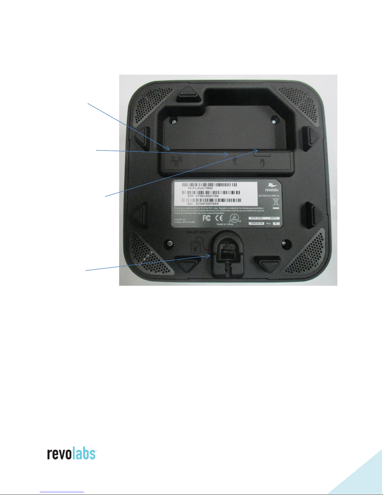
Setting up the system
Ethernet
USB Port
Microphone
(UC1500 only)
Dialer
All connectors can be found on the bottom of the case unit.
Port
Ports
Port
Page 13
13
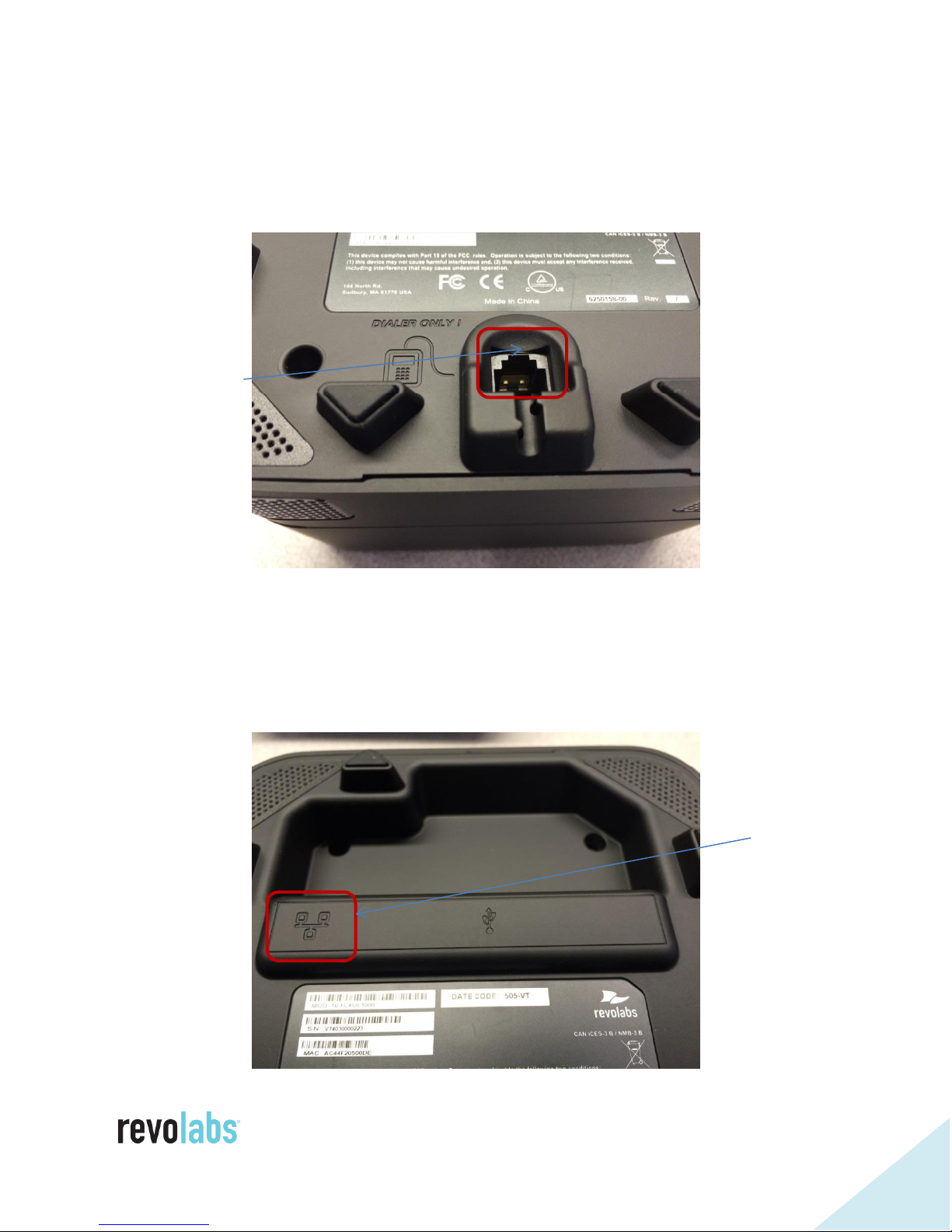
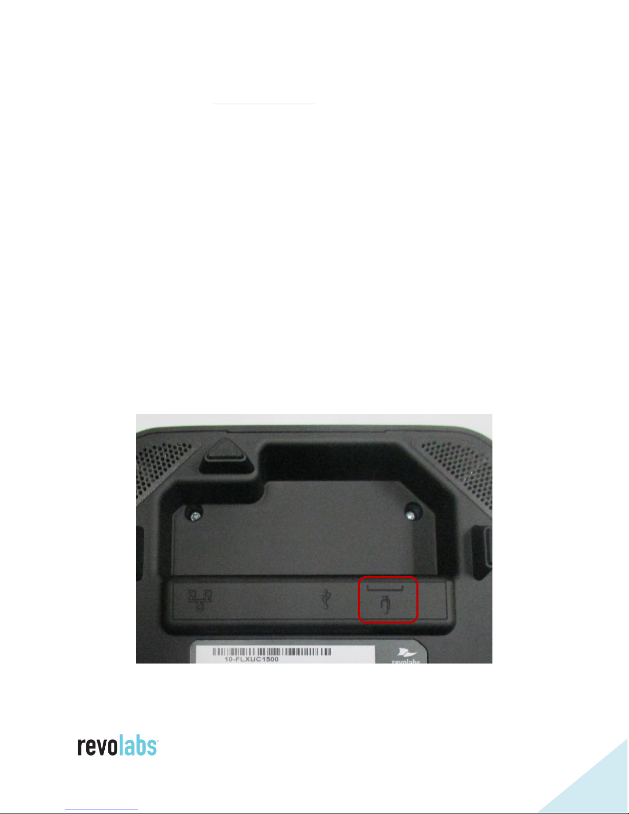
Connecting the Dialer
Dialer Connection
Network port
Use the captive cable of the dialer and insert the connector into the “Dialer
Only” port on the base unit until it clicks into place. Use the routing on the
bottom of the dialer to adjust the length of the cable to your requirements.
Connecting to an IP Network for VoIP Calling
The FLX UC 1000 and FLX UC 1500 are designed to be powered using 802.3af,
Power over Ethernet (PoE). If you have an Ethernet port that does not provide
PoE, a PoE Power Injector can be ordered from Revolabs to provide the device
with power.
Page 14
14
Connect one end of the Ethernet cable into the network connection port on the
USB Connection
bottom of the base unit using the network port. Press the Ethernet connector
until it clicks into place. Connect the other end of the Ethernet cable into a
jack providing PoE or a PoE adapter. The phone will power on. When it is
ready to use, the base will chime and the dialer will display the home screen.
If the Ethernet cable needs to be removed from the FLX UC 1000 or FLX UC
1500, be sure to depress the lever on the connector and pull the cable out
gently. Using force when removing this cable may damage the cable and
render it useless.
In order to place and receive VoIP calls, your FLX UC 1000 or FLX UC 1500 will
need to be registered with a call manager. See the section in this document
called “Configuring the FLX UC 1000 or FLX UC 1500 for your VoIP Network”
to register your device with a call manager.
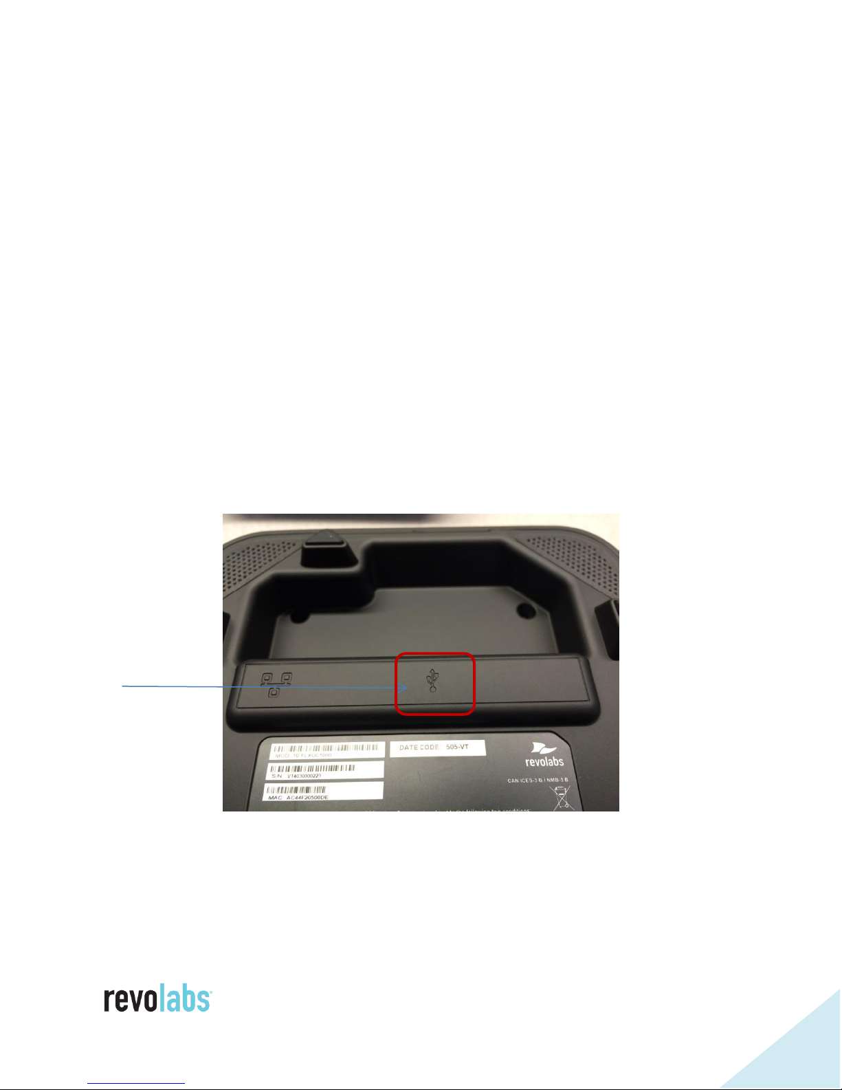
Connecting to a Computer
Using the included USB cable, connect the mini USB side of the cable into the
port identified by the icon on the bottom of the base unit.
Connect the other end of the cable to the USB port on the computer running
the third party softphone, webinar, or conferencing application.
The computer may detect new driver software and install it; wait until the
install has completed before continuing. A USB symbol will be shown in the
FLX UC 1000 or FLX UC 1500 dialer screen when the computer is connected.
Page 15
15
For optimal audio performance when using a Window computers, please follow
the instructions in the appendix section. No additional configuration is
required when using Apple OS X or Chrome OS devices.
If a USB cable longer than the length of the one provided is required, an
approved USB extender should be used. The following USB extenders have
been tested and approved for use with the FLX UC 1000 or FLX UC 1500.
Please note the distance supported by each USB extender varies and is defined
by the manufacturer’s specifications:
USB Ranger 2212 Cat 5 Extender (IC2212R-05-307276) from Icron
Technologies
USB 1.1 Rover 1850 Single Port Cat 5e extender from Icron
Gefen USB 2.0 Extender
Extron USB Extender
Connecting Extension Mics
The FLX UC 1500 includes two ports on the base unit to connect the extension
microphone.
Page 16
16
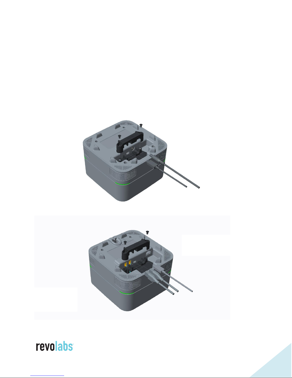
Using the Cable Clamps
FLX UC 500
FLX UC 1000
FLX UC 1500
To help securing the cables connected to the UC products and support that
they are not unintentionally removed, Revolabs provides a cable clamp kit.
The same kit works for the FLX UC 500, the FLX UC 1000, and the FLX UC
1500. Place the bottom part of the cable clamp into the cable cavity of the UC
unit before connecting the cables. Once the cables are connected and fit into
the respective areas of the cable clamp, place the second part of the cable
clamp on top, and using the two screws included with the kit fasten the clamp.
Page 17

17
User Interface
Base Unit
The base unit provides volume up, volume down, mute, answer, and hang-up
buttons. Mute status will be reflected on the LEDs on the four corners of the
device; when microphones are active, these LEDs will be green when the
system is unmuted and red when the system is muted.
When the microphones are not active, the lights can be configured for an idle
color with options of solid amber, solid green, or unlit (default). In order to
change this color, an administrator can use the web UI or the settings menu on
the dialer to configure the desired idle color.
For additional call control functionality, i.e. using the device buttons to hang
up and answer calls using the preferred third party softphone, webinar, or
conferencing application, refer to the FLX UC Device Manager section in this
manual.
Dialer
The display on the dialer presents a series of screens as an interface for using
the device and configuring device settings. The details of those screens are
described in this section.
Page 18
18
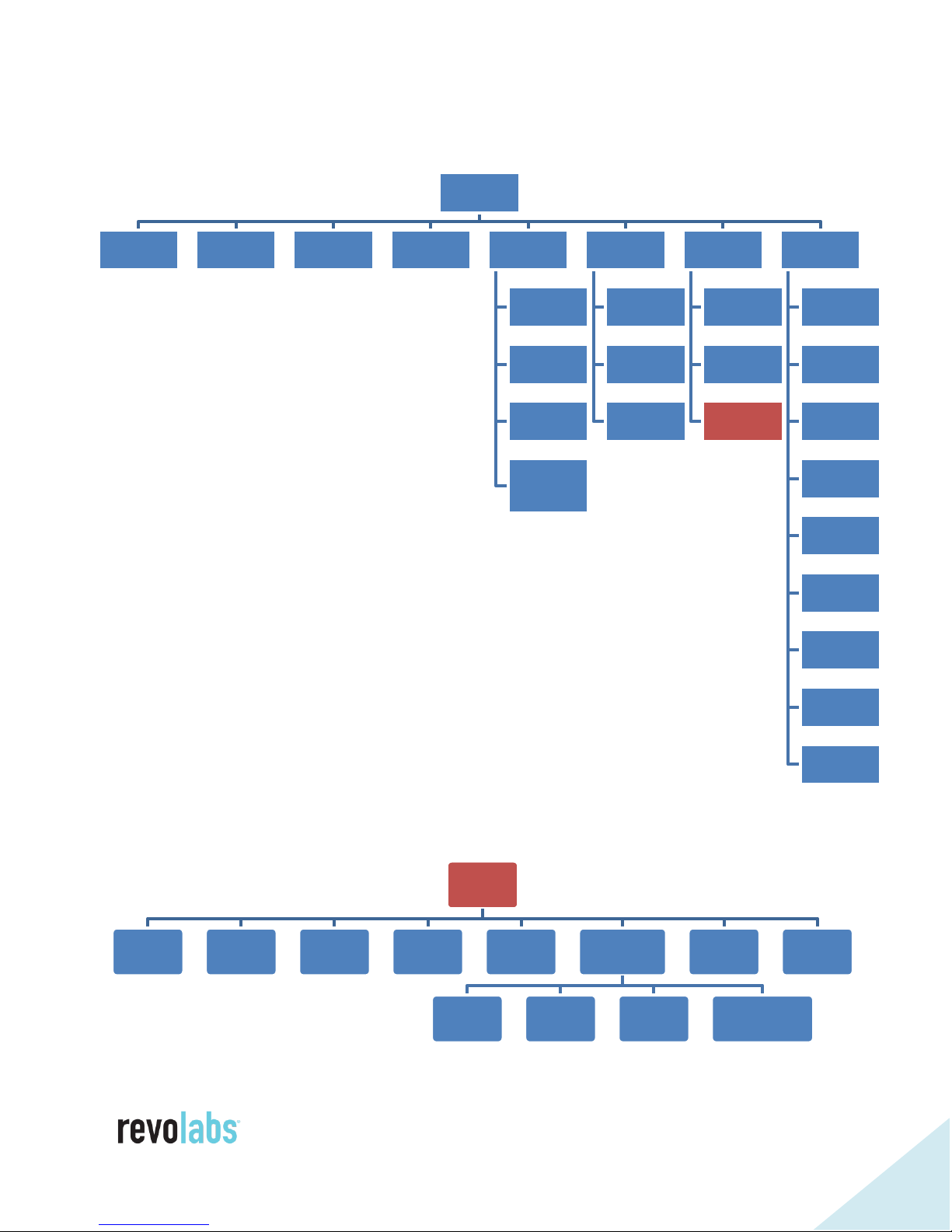
Menu Tree
Admin
Settings
Password
VoIP
Settings
IPv4
Settings
VLAN
Settings
USB
Settings
Advanced
Audio
Room Size
Speaker
EQ
High Pass
Filter
Highly
Reverberant
Room
Date/Time
Setting
Web
Access
Main Menu
Dialer (1) Recents (2) Contacts (3) Voicemail (4)
Forwarding
(5)
Always
Busy
No Answer
No Answer
Delay
(seconds)
Audio (6)
Speaker
Volume
Ringer
Volume
Ring
Selection
Settings (7)
Language
Selection
Display
Settings
Admin
Settings
Info (8)
Product
Name
IP Address
Mac Address
Base FW
Version
Base Serial #
Dialer FW
Version
Dialer Serial #
Call 1
Statistics
Call 2
Statistics
Page 19
19
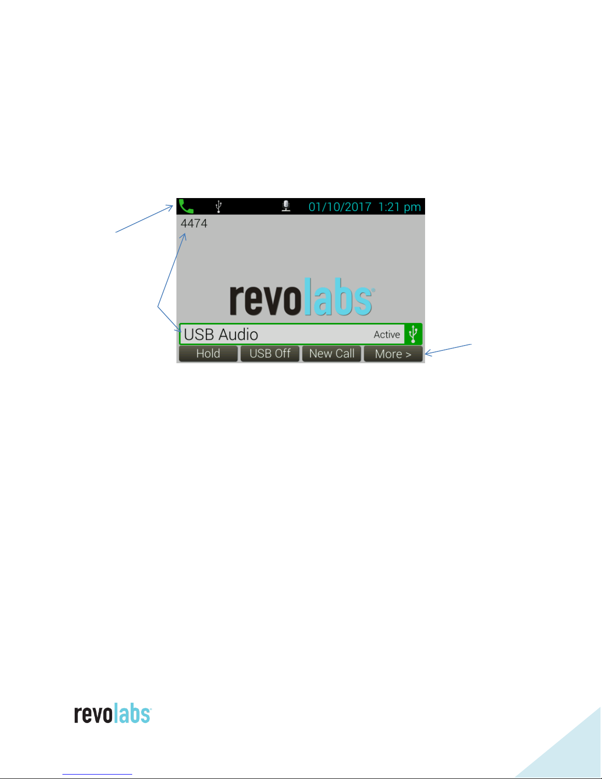
Home Screen
Quick Reference Bar
User ID and
call information
Soft Key
menu options
When the device is powered on, the device will display the home screen. The
home screen provides information in three key areas: a quick reference bar on
top, information about the user ID of the device and call activity in the center,
and soft keys menu options on the bottom.
The quick reference bar provides information regarding the call status of the
system. The information available includes:
Call Icon (in Green): Displays information about call status (No Call, Call
in Progress)
Mute Indicator (microphones muted or unmuted)
USB Icon: Displays when a USB connection is established between the
FLX UC 1000 or FLX UC 1500 and a USB host (e.g. computer)
Do Not Disturb (DND): Displays when the system is configured for do not
disturb.
Voice Mail Icon: Displays when a voice mail is available
Missed Call: Displays when a call has been missed
Extension microphone status (FLX UC 1500 only): Displays the number
of connected extension microphones
Date: Displays current date. The format is configurable in the menu or
web interface
Time: Displays current time. Time zone is configurable in the menu or
web interface
Page 20

20
The center area displays information on the status of USB and VoIP
connections. If a VoIP connection is configured for the unit, the user ID is
displayed directly under the quick reference bar in the upper left side of the
screen. If a VoIP user is configured but not registered or errors occurred
during registration, that status and possible error messages are displayed
instead.
Below the VoIP user ID information for active calls is being displayed. The
information for up to two concurrent VoIP calls is and on the USB audio
connections is provided. If no calls are active no information is displayed and
the Revolabs logo is seen instead.
The call state is indicated by the color of the bar:
Incoming Call: Yellow
Call in Progress/Active: Green
Call on Hold: Orange
Call Ended/Interface Inactive: Red
The soft key menu options are displayed at the bottom of the screen.
Depending on configuration of the USB interface, different home screen menu
options for the soft keys are offered.
When the USB port is configured as “User Determined” (factory default) the
following soft key options are presented:
[Calls]: Redirects to the Recent Calls menu
[USB On]: Turns USB audio on if USB audio is set to User Determined
[New Call]: Opens the Dialer menu
[More >]
After pressing [More >]
[DND]: Toggles Do Not Disturb mode
[Contacts]: Opens the Contacts menu
[< More]
When the USB port is configured as “Always On” the following soft key options
are presented:
Page 21

21
[Hold]: Places the current call (USB audio) on hold
[New Call]: Opens the Dialer menu
[Conf]: Adds a new call to the existing (USB audio) call
[DND]: Toggles Do Not Disturb mode
When the USB port is configured “Always Off” or “USB calls only” the following
soft key options are presented:
[Calls]: Redirects to the Recent Calls menu
[New Call]: Opens the Dialer menu
[DND]: Toggles Do Not Disturb mode
[Contacts]: Opens the Contacts menu
The difference is the between these two settings is the behavior when “New
Call” is being selected. When the USB connection is always off, only the VoIP
dialer is offered. If “USB calls only” is selected, the user can start a USB call.
Menu Options
Main Menu Screen
To access the Main Menu Screen, press the “menu” button at the top left of the
Dialer screen.
To navigate the Main Menu, use the arrow keys to move the shaded circle to
highlight the option you wish to select.
Pressing the OK or Select buttons while highlighting any of these options will
open the appropriate submenu. Alternatively, pressing the number
corresponding to the option also opens the submenu:
Page 22

22
1 - Dialer
2 – Recent Calls
3 - Contacts
4 - Voicemail
5 - Forwarding
6 - Audio
7 - Settings
8 - Info
Using the Back button will bring the user back to the Home Screen.
Page 23

23
Dialer Submenu
In the dialer submenu a phone number can be entered using the keypad. The
keypad supports the numbers 0-9, the star and hash-sign. In addition, when
holding the “0” key for about 2 seconds, a “+” is added to the dial string.
Please be aware that the Call Manager needs to be set up to handle the special
characters *, #, and +.
A pause can be added into a dial string by holding down the “*” key for about 2
seconds. The Pause is indicated by a “,” in the string.
The soft keys available on this screen are:
Dial: Attempts to dial the number entered. The Green Call button to the
upper right of the screen can also be used to call the number (the green
Call button on the base cannot be used to attempt to dial the number –
pressing the green Call button on the base clears the number, takes the
phone off hook, and the user hears dial tone).
<x: Backspace. Deletes the last typed number
Cancel: Leaves the dialer screen and returns to the previously opened
screen
Clear: Deletes the entire number typed
Page 24
24
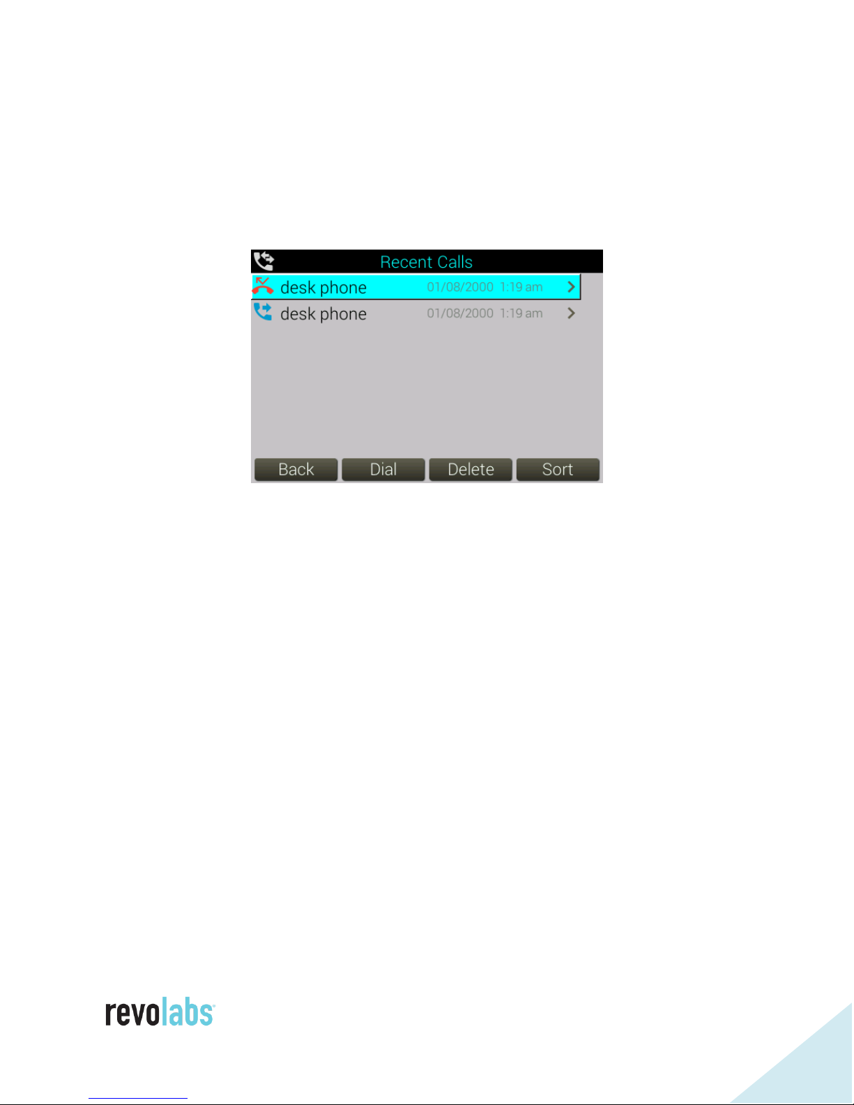
Recent Calls
This submenu displays recent calls to or from the phone. Each call is listed by
a name or the number, and the type of call: a call initiated from the phone, a
received call, or a missed call. The list can be navigated by using the up and
down arrow keys. From this list, the selected call can be redialed or deleted
using the corresponding soft keys.
The list can be sorted to display all calls, missed calls, dialed calls, or received
calls.
An individual call entry can be selected using the right arrow key or “OK”
button, opening an additional information submenu for that call. In that
submenu, the following information for the call is displayed:
Name
Number
Time (Date and time of call)
Duration
Type of Call: Missed, Dialed, Received
From that menu, the call can be saved to contacts, deleted, or dialed.
The web UI allows disabling the functionality to keep recent call information. If
the functionality is disabled, the recent call list will show as empty and call
information is not stored.
Page 25
25
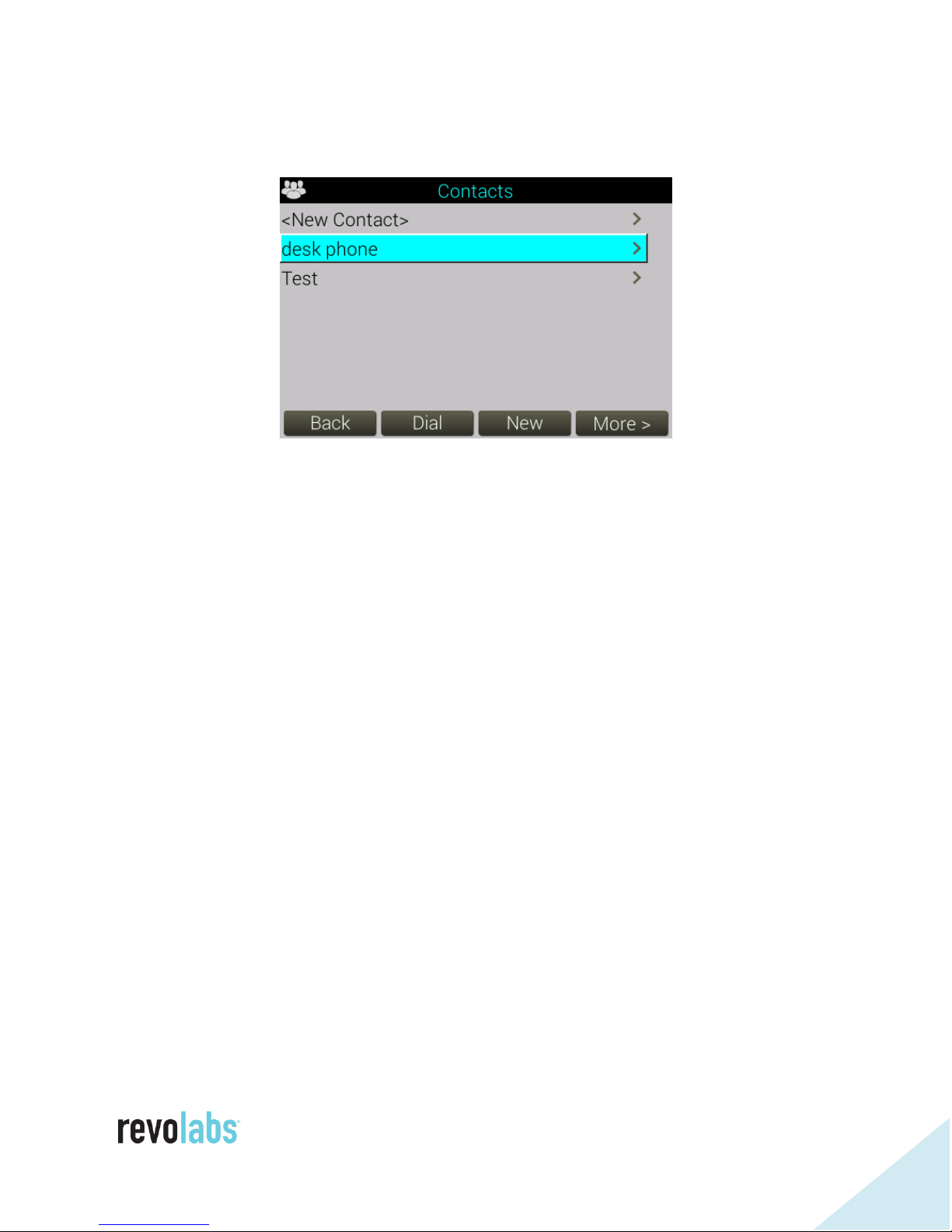
Contacts
This submenu allows managing the phone’s internal contacts list.
The list can be traversed by using the up and down arrow keys.
The highlighted contact can be dialed using the dial button or the green call
function key.
New contacts can be added from this menu. The Name and three phone
numbers, Work phone, Mobile phone, and Home phone, can be entered for a
contact. One of the three phone numbers can be set as the default number by
selecting the “OK” button while the number is highlighted – a green radio
button icon is shown to the right of the default number.
An existing contact can be edited or viewed with the right arrow key, “OK”
button, or by selecting the “More” and then the “View” Soft Key.
The menu also allows deleting (“More”, then “Delete”) of contacts.
When editing or adding a contact, a speed dial number can be assigned to that
contact. The speed dial menu shows available speed dial numbers. To allocate
the contact to a speed dial number, hold down the button on the keypad with
the corresponding number, or highlight an available number and press the
Assign soft key.
When using speed dial to call a contact, the FLX UC 1000 or FLX UC 1500 will
use the default number for that contact.
A new or changed contact can only be saved if at least one phone number is
entered.
Page 26
26
The web UI allows disabling changes to the contact list from the Dialer.
Voicemail
Selecting this submenu will call the mailbox assigned to the device. If no
voicemail has been configured an alert popup will appear, stating “Voice Mail
number has not been configured yet!”
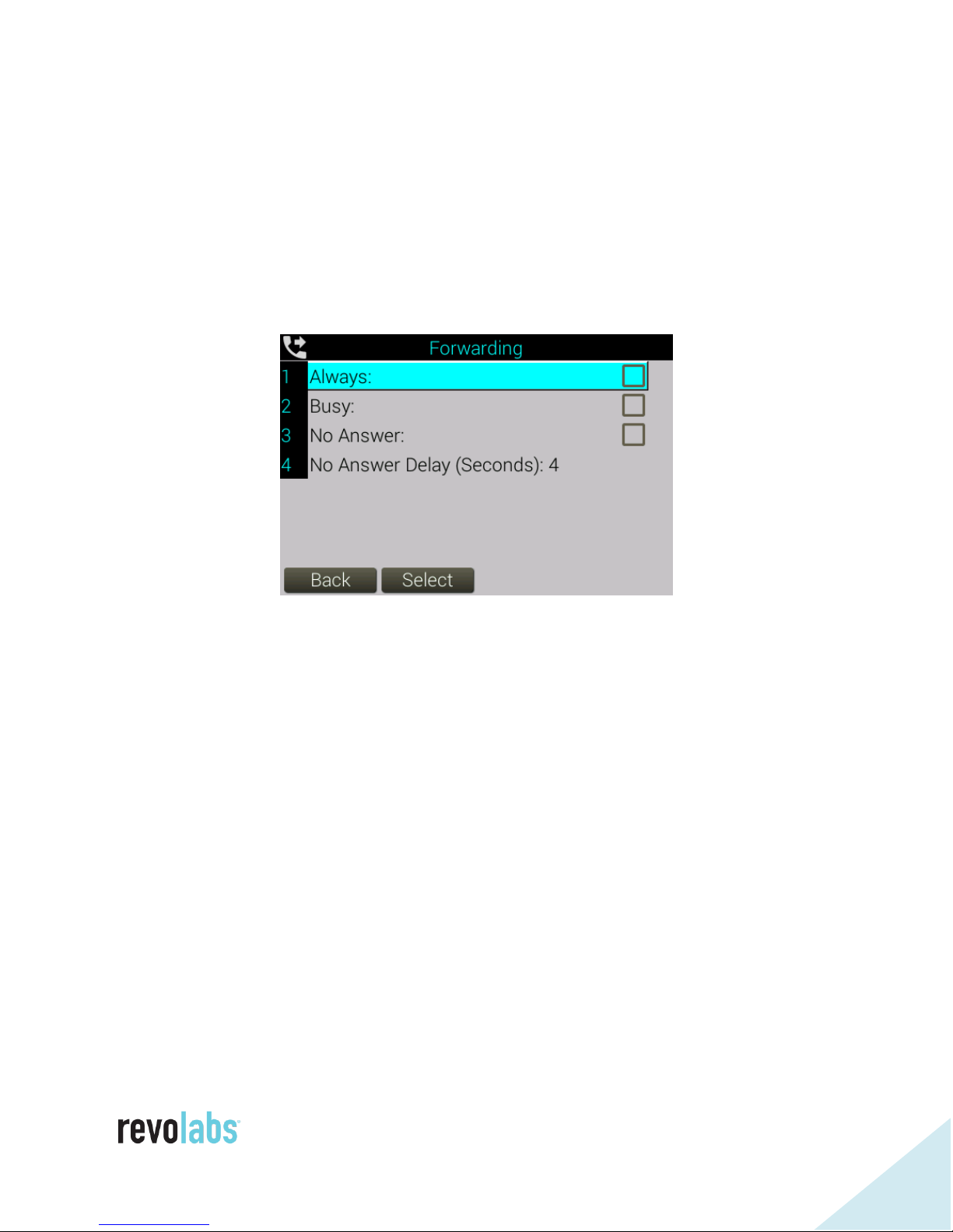
Call Forwarding
Enabling call forwarding will forward calls when certain conditions are met.
Enabling “always” will forward all calls. “Busy” will forward calls when both
SIP lines on the phone are busy. No answer forwards calls after a certain time
when the call was not answered.
When a forwarding option is selected, a popup will appear asking for the phone
number the calls should be forwarded to.
Wait time before an unanswered call is forwarded can be set from 2-30
seconds.
The web UI allows disabling changes to the call forwarding settings from the
Dialer.
Note: Call Forwarding settings require the call manager to support this
feature. Call forwarding on no answer requires the call manager to
support three call appearances on the phone to detect the call that
needs to be forwarded. If voice mail is set for the extension, the noanswer delay needs to be selected shorter than the voice mail delay,
Page 27
27
otherwise the call will have been presented to voice mail before it is
forwarded by the phone.
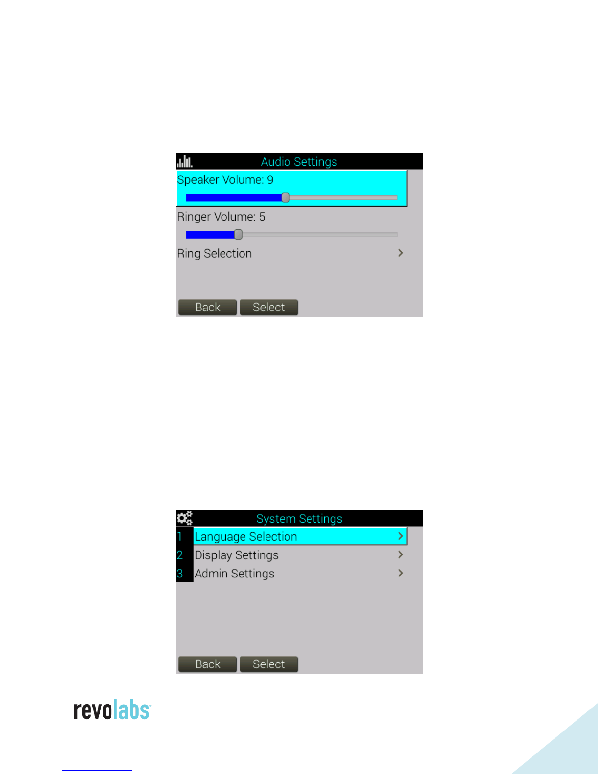
Audio
“Speaker Volume” and “Ringer Volume” sliders go from 1-18. The “Ringer
Volume” slider plays a test tone for every number change. The “Speaker
Volume” slider does not.
Ring Selection opens a menu where ring tones can be selected. You can test
the ringtones before selecting in this menu by using the [Play] button at the
bottom of the screen.
The option to change ring selection can be disabled in the web UI.
Settings
Page 28
28
The Settings menu might offer up to three options: Language Selection,
Display Settings, and Admin Settings.
Language Selection allows selecting the screen language. After changing the
language the FLX UC 1000 or FLX UC 1500 will reboot after which the new
selected language will be used for all screen content.
The language selection menu can be disabled using auto configuration or the
web UI. When disabled, the option is not shown in the dialer screen.
Display setting allows setting the screen brightness using values between 1
and 15. It also allows defining the timeout for the Backlight. The screen will
remain lit for the selected time after an action was taken, then the backlight
will be turned off. Selecting “Never” for Backlight Time means the screen will
not dim at all.
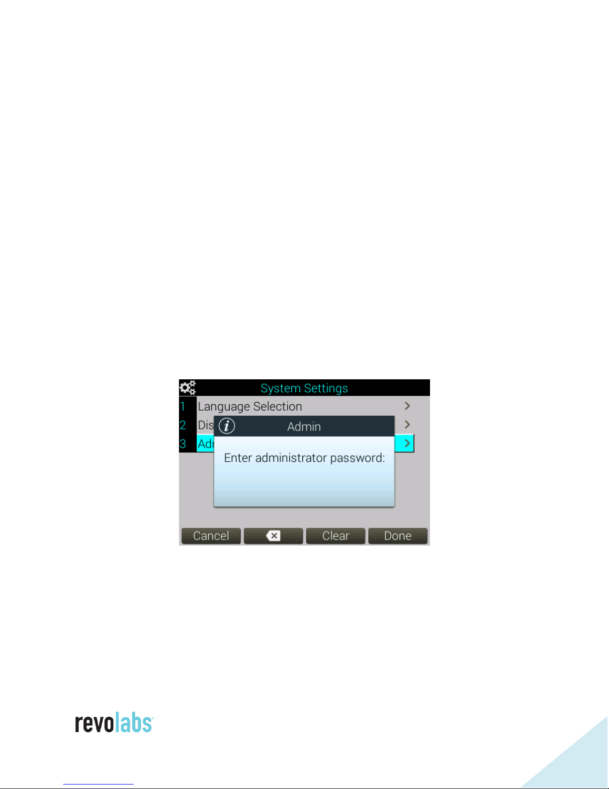
The Admin Settings menu is protected with a numeric password. The default
password is 7386 (REVO on the phone dial pad), but it is user changeable. The
Web-UI and the dialer use the same password, changing it in one interface
affects both interfaces logons.
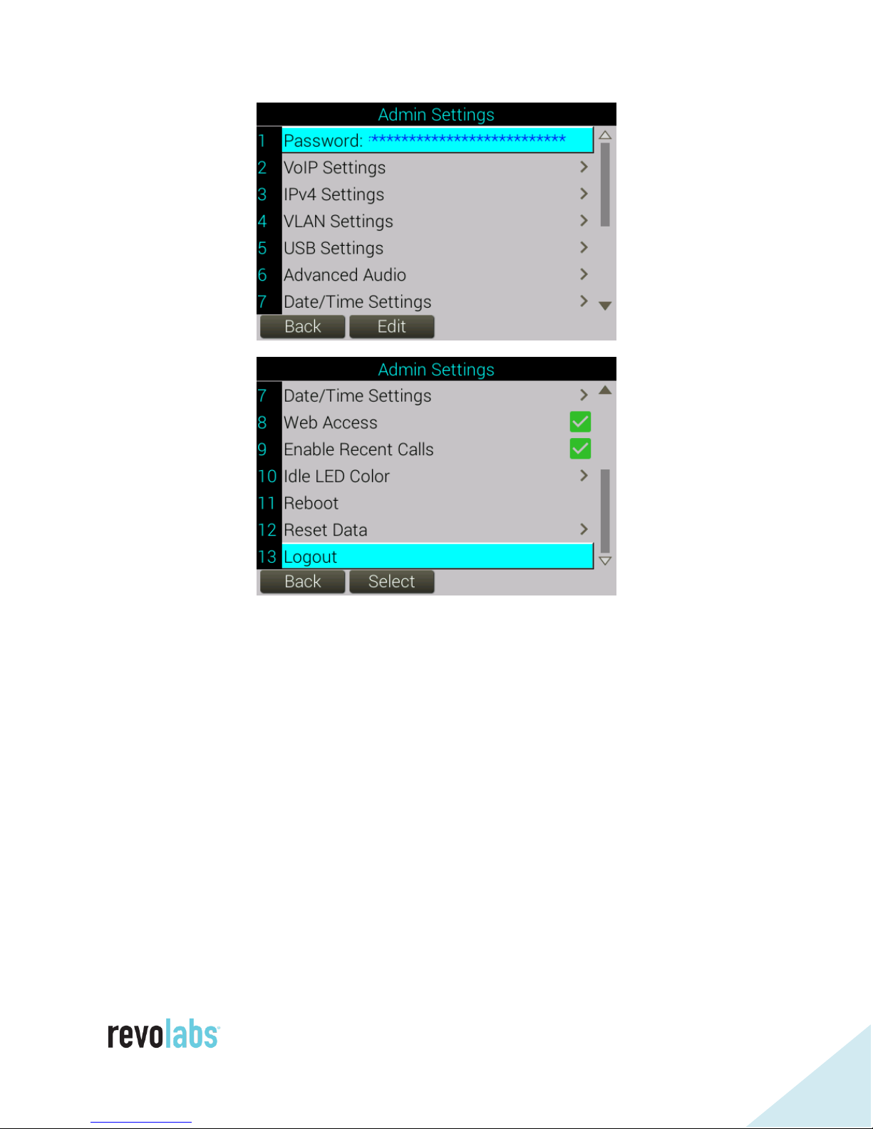
The Admin Settings submenu allows several administrative actions to be taken:
Page 29
29
Selecting Password allows the user to delete the current password and create a
new numeric password.
The VoIP Settings menu allows providing and changing of the VoIP parameters,
like registrar address or name, user name, and password.
In the IPv4 Settings menu the user can enable DHCP, or provide a fixed IP
address with subnet masks and other required settings.
The VLAN Settings menu allows specifying whether a VLAN is used, and either
have the phone detect it automatically, or provide the VLAN identifier
manually.
The USB Settings menu allows defining the behavior of the USB connection. It
can be always disabled in which case the FLX UC 1000 or FLX UC 1500 act
like a VoIP phone only, it can be always enabled, in which case the USB
Page 30

30
connection is always life and providing an audio stream via USB to the
connected device. It can be user determined, in which case the user can
determine the status of the USB line through the dialer. If USB calls only is
selected, the USB connection can only be active when a USB call is detected.
This requires the communication application to send according signals on the
USB interface, indicating the call state. USB audio can only be activated for a
USB call.
Advanced Audio Settings will be described further down in this section.
In the Date/Time submenu NTP servers providing network time can be
specified. The menu also allows specifying the time zone in which it is being
used. Finally, the format in which dates and times should be presented in the
dialer can be selected.
Note: Daylight savings time rules that might be used in the location where
the phone is being installed can be set using the web interface.
The Web Access check box allows enabling / disabling the web access to the
phone.
Enabling Recent Calls allows storing data on the recent calls made to or from
the phone. Disabling “Recent Calls” displays a popup asking “Do you want to
clear the recent call list?”
If “Yes” is selected, all call data stored on the device will be deleted.
If “No” is selected, the call data of previous calls will be saved, but no
new call data is added, and the call data cannot be accessed until Recent
Calls is re-enabled.
The Idle LED Color setting allows specifying the LED state when the system is
idle and USB audio is disabled.
Reboot reboots the device.
Reset Data allows resetting of factory defaults and removing usage data, either
for the whole system, or by area.
And finally, the admin user can select to log out of the interface.
Advanced Audio Settings
Page 31

31
The Advanced Audio submenu enables the user to specify audio settings and
the room environment.
Default Call Line defines the behavior of the green off-hook button. By default,
this setting affects the VoIP call and takes the phone line off-hook. When the
Default Line is set to USB, pressing the off-hook button will send an off-hook
signal on the USB interface instead. If None is selected, the user is asked
which interface should be activated when pressing the off-hook button.
Room size allows specifying the size of the room in which the FLX UC 1000 or
UC 1500 is being used. It affects the behavior of the gain control to ensure
that in larger rooms everybody is heard, and in smaller rooms sounds that are
not coming from the meeting itself are not gained.
Speaker EQ provides three pre-defined EQ settings to improve the speaker
audio. We recommend using the Voice Enhance setting.
High Pass filters should be enabled in rooms with high background noise.
These noises are typically in the low frequency level, selecting an appropriate
High Pass Filter will eliminate these frequencies.
The Highly Reverberant Room setting activates a filter that limits audio
frequencies found in reverberant rooms. A room might be highly reverberant
when it has one or more window walls, wood or concrete floor, or concrete
ceiling. An echo can be heard in these rooms for example when clapping
hands. The FLX UC 1000 and UC 1500 conference phones have been designed
to provide the truest audio experience, capturing the audio in the room as it is
experienced in the room itself. This might cause an over-representation of low
frequencies in reverberant rooms. The Highly Reverberant Room setting limits
these frequencies.
Page 32

32
System Information
The System Information menu provides information about the product as well
as statistics information on VoIP calls.
Page 33

33
Web User Interface (Web UI)
Using the IP address of the FLX UC 1000 or FLX UC 1500 and assuming that
web access has not been disabled using the dialer, the unit can be accessed
using a web browser by entering the IP address of the phone in the address
line. Supported browsers are Microsoft Edge, Google Chrome, and Mozilla
Firefox.
When accessing the phone the login page will be displayed. A password is
required to log in to the device. Unless the password was previously changed
using the dialer or the web UI, the factory default password is 7386.
Generally, after a time-out period the user will be automatically logged-out of
the web interface. However, if it is expected that more time is required for
configuring the phone, the login page provides a check box to disable to auto
log-out on this system, leaving the user logged in until an explicit log-off is
triggered.
Home Screen
Once logged in the web interface will display the home screen. The home screen
provides current status information about the unit, including current call
information and connected microphones for the FLX UC 1500.
Page 34

34
The home screen allows initiating an immediate restart of the device.
In all screens of the web UI a logout icon is displayed in the upper right corner
allowing the user to log off from the unit.
The top menu line allows accessing the different pages of the web UI. Hovering
over any of the symbols will show the available options. The Settings options
allow configuring the unit. The Tools menu allows system firmware upgrades
and uploading / downloading of log files and configuration files. The Settings
and Tools options are described in more detail in the following sections.
Please note that for any changes to take effect, the “submit” button on the web
page has to be clicked. Otherwise changes will get lost when leaving the page
without clicking “submit” before.
Settings
Admin
The admin tab allows setting of several administrative parameters.
Security Settings
Page 35

35
The Security Settings section allows the user to change the system password.
Any change to the password will affect access to the protected submenus on
the dialer as well as web UI access. The password has a minimal length of four
digits, any other characters are not allowed. Once a valid password has been
entered, it needs to be entered a second time to protect against typos and
unwanted changes.
If recent calls is enabled, the phone will keep a list of recent phone calls in its
memory which can be browsed using the dialer.
Enabling the web access setting allows the FLX UC unit to be accessed using a
web browser. If this setting is disabled, web access is not possible to the phone
and the setting needs to be changed either through the dialer, or a parameter
change as part of a DHCP auto configuration.
When Require https is enabled, the web interface will switch from http to https.
Please note than when using https, as the device cannot have a certified
security certificate, your web browser will warn you of a potentially unsecure
connection.
Dialer Restrictions
Page 36

36
The Dialer Restrictions section allows disabling some features in the dialer
interface. Selecting the respective restriction will disable or remove the
corresponding options in the dialer user interface.
Page 37

37
Device Settings
The Idle LED color setting allows defining the behavior and color of the mute
LEDs on the main unit and the dialer when no audio activity is present (no
VoIP or USB call, USB interface inactive).
Brightness and Backlight timeout impact the backlight behavior of the dialer.
Deployment Server Settings
The Deployment Server Settings allows specifying automatic ways to download
configuration data to the phone on a reboot.
Factory Default, the system is set to support automatic server discovery for a
deployment server using DHCP option 66 and DHCP option 150.
Page 38

38
When deployment server is enabled but automatic server discovery is disabled,
a primary (and secondary) deployment sever can be statically entered from
which the phone will download the configuration data at start-up.
Using DHCP option 66, the return can be a tftp address or an http address.
Option 150, a list of tftp servers or http addresses might be delivered back.
When using the static server addresses, tftp addresses or http addresses might
be provided.
When using the deployment server, the FLX UC 1000 or FLX UC 1500 will look
for a file named <<MAC-address of unit>>.xml in the provided location(s). See
the remote configuration section for sample configuration and a list of the
available configuration parameters.
The provisioning interval allows specifying the time interval when a system
should re-check for possible configuration changes. This interval can be set
between 1 minute and 31 days (44,640 minutes). If a change to the
configuration file is determined, the phone will reboot and restart using the
new configuration file.
Audio
The Audio section of the Settings menu supports managing the audio behavior
of the UC FLX 1000 and UC FLX 1500 phone.
Page 39

39
The Ring tone dropdown menu allows choosing from a list of available
ringtones for the phone. The selected Ringtone will play on the phone once
“Submit” has been clicked to save changes to the ringtone.
Default speaker volume allows specifying a default loudness of the phone.
When all active calls end, the system will automatically return to that setting.
Or on a reboot, the system will return to that volume setting. “0” will disable
this function.
The Equalizer setting allows selecting one of a list of pre-defined speaker
equalizations. The available choices are Voice Enhance, Bass Boost, and
Treble Boost.
The High Pass filter affects the microphones and can be used to filter out low
frequency noises in the room. The high pass filter can be disabled (None), or
set to the provided frequencies of 110Hz, 140Hz, 175Hz, or 225Hz.
Page 40

40
USB Audio can be set to Always Enabled, Always Disabled, User Determined,
or USB calls only. On “Always Enabled” the USB audio path for the
microphones and speakers is always open unless the USB call is put “on hold”
from the dialer. The “Always Disabled” setting disables the USB audio path and
it cannot be enabled from the dialer. “User Determined” allows the user to
switch USB audio on and off from the dialer. And finally “USB calls only”
allows the USB audio path only to be activated when the connected device
signals that a USB call is in progress. This depends on the UC application.
The Highly reverberant room setting activates a filter that limits audio
frequencies found in reverberant rooms. The FLX UC 1000 and FLX UC 1500
conference phones have been designed to provide the truest audio experience,
capturing the audio in the room as it is experienced in the room itself.
However, specifically when used with codecs limiting the audio to a narrow
frequency bandwidth, this might cause an over-representation of low
frequencies. The Highly reverberant room setting limits these frequencies.
Room size allows specifying the size of the room in which the FLX UC 1000 or
FLX UC 1500 is being used. It affects the behavior of the gain control to
ensure that in larger rooms everybody is heard, and in smaller rooms sounds
that are not coming from the meeting itself are not gained.
Page 41

41
Media Settings
In the Media Settings the audio codecs used for VoIP calls and supported by
the FLX UC 1000 and FLX UC 1500 can enabled, arranged in priority, or
disabled. This is done by dragging and dropping them into the respective area
or position.
Supported codecs on the FLX UC 1000 and FLX UC 1500 are G.711 u-law and
G.711 a-law, G.722, G.726, and G.729.
The Codec ptime override can be set to values between 10 and 100
milliseconds. Factory preset is 20 ms.
Page 42

42
Calls
The “Enable message waiting indication” allows a voicemail symbol to appear
on the quick-reference bar at the top of the Dialer screen when a voice message
waiting. Voice Message indication requires the extension to be configured to
support voicemail.
Checking the “Set Do Not Disturb (DND) mode” activates DND on the phone.
While activated incoming callers will be immediately forwarded into voicemail if
it is configured for the phone or receive a busy tone and the device will not
ring. Missed calls will still be recorded in the recent calls list as long as
collection of recent call information is enabled.
A phone that has “Enable Auto Answer” checked will automatically go off-hook
when a call arrives and answer that call without user input.
“Default Call Line” allows specifying the behavior of the off-hook button on the
dialer and the main unit. If the default call line is VoIP, the phone will go into
telephone dialing mode when off-hook is pressed. If the default line is USB,
Page 43

43
pressing the off-hook button will send a start-call signal over the USB HID
interface to the connected device.
The “Voicemail number” field allows to configure which number is called from
when the voicemail menu is selected in the dialer.
Maximum call duration allows limiting calls to a specific length, and causes
calls to end after the specified time. Setting the maximum duration of “0” or
leaving it blank disables the maximum duration and allows for calls of any
length.
The “Dial Plan” field allows specifying a dial plan for the phone. The syntax for
the dial plan is described in detail in the Advanced Operations section of this
manual.
Forwarding Settings allow specifying automatic forwarding behavior of the
phone. Selecting any of these will require a phone number to be entered to
which calls will be forwarded. When selecting “Forward on no answer” a
timeout has to be defined after which the call will be forwarded.
Page 44

44
Network
The Network section allows specifying the IP configuration for the phone.
Factory default, the phone is set to DHCP enabled and no further IP settings
are required. However, if a static IP address is to be assigned to the phone,
“Enable DHCP” needs to be unchecked, and the static IP parameters can be
provided.
If a VLAN is used for Voice traffic, the Voice VLAN option allows to specify
whether the VLAN should be detected automatically or whether a manual VLAN
identifier is provided. If no VLAN is used for Voice traffic disable this option.
The FLX UC 1000 and FLX UC 1500 phones support LLDP to discover VLANs.
Page 45

45
Authentication Settings
Authentication Settings provides the option to enable 802.1x authentication on
the FLX UC phones. To enable 802.1x authentication, check the Enable
802.1x authentication setting. Supported authentication types are MD5 and
Protected EAP (Protected Extensible Authentication Protocol). A username and
password are needed to complete the authentication process. If Protected EAP
(Protected Extensible Authentication Protocol) is selected the server-side public
key certificate will need to be uploaded to the FLX UC 1000 or FLX UC 1500.
Region
Regions settings allow to change localization of the FLX UC units.
System Language affects the user interface of the dialer. Chinese, English,
French, German, Italian, Japanese, Portuguese, and Spanish are supported.
Call progress tones define the tones heard during call set up and other phone
related tones. Several different audio tones as they are found in different
countries and regions are supported.
Page 46

46
Time zone allows to select the time zone the phone is being used in, managing
date and time shown in the dialer screen.
Time Settings
In the Time Settings section the date format used in the dialer can be selected.
Date can be set as MM/DD/YYYY, DD/MM/YYYY, or YYYY/MM/DD. The time
display can be changed between 24 hour format and 12 hour format.
The FLX UC phones support up to 4 network time servers to provide NTP time
information. These can be local servers or network servers.
Page 47

47
Daylight Savings Settings
Daylight Savings settings allow to enable or disable Daylight Savings time for
the phone display. If enabled, rules for the start date and time as well as the
end date and time need to be provided. Factory default US daylight savings
time is enabled and configured.
Page 48

48
SIP
In this menu the SIP configuration settings are located configuring the FLX UC
1000 or FLX UC 1500 with the call manager.
Registrar and Back-up registrar (if configured) are the IP addresses or server
names of the Call Manager. If configured, a Proxy address can be provided,
and an indicator whether the proxy should also be used for registration. The
VoIP realm, typically “*”, can also be provided.
Page 49

49
The next section contains the user name, User ID and password for the logon
to the Call Manager. Please note that Call Managers often use different names
for these parameters and a correct mapping is required for the logon to the call
manager to be successful.
Page 50

50
Configuration Settings
The Configuration Settings section offers several advanced SIP settings. These
parameters should be aligned with the call manager configuration.
The FLX UC 1000 and FLX UC 1500 phones support several means to
transport DTMF information entered during a call to the far end. This setting
should be consistent with the method supported by the call manager.
Page 51

51
The SIP standard defines the payload range for DTMF tones. Some call
managers do not accept all of the payload types, select the supported payload
type in this setting.
Lastly, some call managers require RFC 2543 for on-hold media. For these call
managers, change the Media on-hold message to that value.
Transport
The Transport section of the management interface allows configuring specific
transport methods based on call manager settings and network and firewall
configurations.
If QoS is enabled, SIP and media packages are tagged to indicate QoS
requirements.
Typically SIP messages are sent using UDP (if available). By checking Enable
TCP transport protocol these messages are sent using TCP instead.
Page 52

52
The remaining parameters on this page allow to specify the ports used for
communication from the device, enable secure RTP, and ICE, TURN, and STUN
settings. These parameters should reflect the call manager and network
environment in which the FLX UC 1000 or FLX UC 1500 is used.
Page 53

53
Tools
The Tools section of the management interface allows importing and exporting
data, resetting the configuration, and upgrading the firmware version.
Update
Update allows upgrading the device firmware of the FLX UC 1000 or FLX UC
1500. Only valid firmware files can be used for an upgrade. Latest firmware
can be found on Revolabs’ website (www.revolabs.com).
The website allows “drag and drop” of a file, or when clicking in the box a file
browser will open to select the firmware file.
Once the firmware file has been identified, clicking the “Update Firmware”
button will initiate the upgrade. Once the upgrade is complete, the device will
restart, and the boot-up chime will sound.
Page 54

54
Contacts
The Contacts section allows to export the current contact list from the FLX UC
phone, or to upload a list to the phone.
“Export Contacts” creates a contacts.csv file that is downloaded to the
connected device. The parameters in the CSV file are Name (contact name),
mobile, work, home (the associated telephone numbers), default (whichever of
the three numbers – mobile, work, home – should be used as the default),
speed (the assigned speed-dial number), and key (a system generated
identifier).
Contacts can also be imported using the Import Contacts section. Contacts
imported that way are merged with the contacts list that may already exist on
the phone. Leave the key field empty when importing a list.
The maximum number of contacts supported on a FLX UC 1000 or FLX UC
1500 is 100.
Page 55

55
Configuration
The configuration page allows downloading the current configuration of the
FLX UC 1000 or FLX UC 1500 phone. This is specifically of interest if several
phone are supposed to be configured in a similar way. It allows to configure
the first phone, export the configuration, and then import the relevant
parameters of that configuration file into other FLX UC systems. For a
description of the configuration parameters see the provisioning section further
down in this manual.
System defaults can be restored in a granular way by selecting which settings
of the configuration to reset to defaults and then clicking the “Reset Defaults”
button. Restore to Factory Defaults restores all settings back to the original
settings.
Page 56

56
Logs
The Logs section allows downloading logging information from the phone for
analysis. Factory Default, verbose logging is not enabled and not required.
Access to logging information is typically only required when environmental
issues with call managers or connected USB devices ae experienced.
Page 57

57
Basic Operations
SIP phone operations
Prior to making any SIP based phone calls on the FLX UC 1000 or FLX UC
1500, the conference phone must be registered with a call manager.
Dialing a Number
There are several ways to dial a telephone number from the FLX UC 1000 or
FLX UC 1500 dialer.
If the phone is configured for VoIP as the default call line, press the green offhook button provides dial tone and allows a number to be entered. The phone
will use a time-out period to determine that the number is completely entered,
and dial the number.
A phone configured for VoIP as the default call line will also enter the dialer
screen automatically if numbers are entered. Once all numbers are entered,
pressing the off-hook button will have the phone dial the entered number.
Whether the phone is configured default VoIP or USB, pressing the “New Call”
button on the dialer will bring up an additional question to select VoIP or USB.
If VoIP is selected, the dialer screen opens and a number can be dialed.
And lastly, the dialer screen can be entered from the Main Menu by selecting
the “Dialer” sub menu.
To dial a number that begins with a plus sign (“+”), press and hold the 0 button
until the “+”appears. Please note that the call manager needs to be configured
to allow dial strings including the “+” symbol.
To include pauses in the dial string, press and hold the “*” key. Pauses are
identified by a “,” symbol in the dial string.
Redialing a Number
The Redial button will redial the last number used to place an outgoing call.
To redial a different number from the recent calls list, open the recent calls list
by either pressing the [Calls] soft key at the bottom of the screen, or select the
“Recents” menu from the Main Menu. Using the navigation buttons select the
desired number and press the green off-hook button to initiate the call, or
Page 58

58
choose the [More >] soft key and then press the [Dial] soft key at the bottom of
the screen to redial that number.
Dialing a Contact
To dial a contact, from the Main Menu, select Contacts. Select the desired
contact from the list using the navigation keys. To call the Default number of
the contact press the [Dial] soft key at the bottom of the screen or press the
green off-hook buttons. To dial one of the non-default numbers of the contact
open the contact, then select the desired number with the navigation keys
before pressing the [Dial] soft key at the bottom of the screen or pressing the
green off-hook button.
Initiating a second call while another call is active
Select [New Call] along the bottom of the screen, enter the second number, and
press the [Dial] soft key or the green off-hook button to establish the second
call. The first call will be put on hold. To switch between calls, select the
desired call in the display using the navigational keys, and then press the
[Swap] button at the bottom of the screen. This will make the selected call
active, and put the previous call on hold. To join the two calls in a conference
call press the [Join] soft key.
Answering an Incoming Call
While on a call, answer an incoming call by hitting the green off-hook button
on the dialer or base. The previously active call will be put on hold.
Ignoring an Incoming Call
To ignore the incoming call, select it through the dialer and press the [Ignore]
button. Alternatively, press the red on-hook button on either base or the
dialer.
Hanging Up a Call
Pressing the red on-hook button will hang up active calls.
USB Audio
To use the FLX UC 1000 or FLX UC 1500 for USB audio, the USB settings in
the system needs to be configured by selecting USB Always Enabled, USB User
Determined, or USB Calls Only.
If the system is not to be used for USB audio it is recommended to select USB
Always Disabled as the USB setting.
Page 59

59
When USB is Always Enabled, the audio connection to the connected device is
always sending and receiving audio data, unless the audio channel is put on
hold. If User Determined is selected, audio is only sent and received when
[USB On] is selected from the Dialer. Otherwise audio is not being sent or
received, and the dialer screen shows USB Audio as Inactive.
USB Calls Only limits USB audio connections to the connected device only to
cases in which the UC application used identifies USB activities as USB calls.
USB audio can only be sent when a USB call has been detected and the FLX
UC device has been notified about it.
The FLX UC devices support integration of audio control with the operating
system of the attached device, and call control (hang-up and answer) with
Third Party Conferencing Applications. Audio control integration is supported
with Windows 10, Mac OS, and Chrome OS. Call control is supported by using
HID (human interface device) commands on the USB connection. Some UC
applications support HID commands natively and therefore can directly
exchange these commands with the FLX UC device. For other applications the
HID commands need to be transformed into application specific commands.
Please refer to the section on the FLX UC Device Manager on more detail on
which applications are supported.
Conference USB and SIP Calls
The FLX UC 1000 or FLX UC 1500 can have two simultaneous SIP VoIP calls
and the USB audio line active at the same time. Any combination of these calls
can be joined into a conference.
To set up a conference call when no calls are active, initiate the first call, then
press the [Conf] button at the bottom of the screen and start the second call.
Both calls will now be active and in a conference call with one another.
To set up a conference call when more than one call is already active, select
one call using the navigation keys, and make it the active call (not on hold).
Then select the second call you wish to include in the conference using the
navigation keys, and press the [Join] button at the bottom of the screen. This
will create a conference call. The third call can be included in the same
conference call by selecting it using the navigation keys and pressing [Join]
again.
Page 60

60
Pressing the [Split] button at the bottom of the screen while the conference call
is selected will separate the conference call. All calls will be separate and put
on hold. To continue with one participant select the call using the navigation
keys and press [Resume] to activate it. To end any of the calls select it using
the navigational keys and press the on-hook button.
NOTE: Hanging up on a conference call you are hosting will hang up on
the connection between the active calls. The conference will not continue
after you leave. Hanging up on a conference you called into will only
remove you from the conference, not affect the other callers.
The FLX UC 1000 and FLX UC 1500 support a maximum of three lines for
incoming and outgoing calls (two SIP calls, one USB call). If the maximum of
calls is reached, no more calls can be made. Call forwarding can be set up to
forward a caller who calls in while the SIP lines are busy.
Using Do Not Disturb
When Do Not Disturb mode is active the device will not ring when calls are
coming in. Depending of the setup, the far end calling the FLX UC 1000/FLX
UC 1500 will receive a busy tone, or if call forwarding is configured, will be
redirected to the call forwarding number. The Do Not Disturb feature can be
configured using the dialer or the web UI.
Page 61

61
Configuring the FLX UC 1000 or FLX UC 1500 for
your VoIP Network
This section will provide details on how to configure the device to connect to a
call manager. The information provided here is general to any call manager,
and provides the details of how to access the configuration settings on the FLX
UC 1000 or FLX UC 1500 to enter in the specific call manager information.
Some sample configuration for specific call managers, including the mappings
of fields, is provided in the appendix of this manual. The Revolabs web site at
www.revolabs.com provides more information and samples for several call
managers.
There are three methods on how the FLX UC 1000 or FLX UC 1500 can be
configured on the network –from the Web UI, using the dialer, or using a
provisioning server with DHCP Option 66 or 150.
Configuring using the Web User Interface
All SIP configuration parameters are available in the Settings - SIP Settings and
the Settings – Transport menus.
Once the required configuration information is entered on each of the sides,
click the “Submit” button on the top right of the screen to save the changes.
It is recommended to reboot the device once all configuration changes have
been performed.
Configuring using the Dialer
The Dialer is not the recommended way to configure the phone as entry,
specifically of characters, through the dial pad is time consuming.
A small set of the SIP settings can be accessed and configured from the Dialer.
From the Main Menu, select Settings, Admin Settings, and then the VoIP
Settings for a list of the available configurations items.
Select any configuration item and press the [Edit] button at the bottom of the
screen to enter editing mode. After providing the necessary information, hit the
[Apply] button to save the changes.
Page 62

62
Once all settings have been changed, return to the “Admin Settings” menu and
select the “Reboot” option. Rebooting the device will apply the changes.
Configuring using a Provisioning Server, Option 66
Option 66 allows IP Phones to download their configuration from a TFTP server.
When an IP Phone starts, it sends a request to the DHCP server for an IP
address. In addition to the IP address the DHCP server send additional
information back to the phone as configured on the DHCP server. Option 66 is
a configuration item that allows providing the address or hostname of a TFTP
or HTTP server to the device.
An http server needs to be configured as
http://<server address>
A ftp server needs to be configured as
ftp://<server address>/user=”<username>”&pass=”<password>”
and where <username> and <password> are the username and password
required to access the tftp server.
Once the FLX UC 1000 or FLX UC 1500 receives the address information of
that server, it tries to access configuration files on that server to auto-configure
the phone during start-up. The configuration file for the specific FLX UC
phone needs to be named <MAC-address of phone>.xml.
Any configuration data provided from the configuration files will overwrite
configuration that might have been entered in the phone previously.
A list of the available parameters with a short description is provided further
down in this manual. A set of sample configuration files is also provided.
Configuring using a Provisioning Server, Option 150
Option 150 allows IP Phones to download their configuration from a TFTP
server. When an IP Phone starts, it sends a request to the DHCP server for an
IP address. In addition to the IP address the DHCP server sends additional
information back to the phone as configured on the DHCP server. Option 150
Page 63

63
is a configuration item that allows providing a list of addresses or hostnames of
TFTP or HTTP servers to the device.
Http servers needs to be configured as
http://<server address>
Ftp servers needs to be configured as
ftp://<server address>/user=”<username>”&pass=”<password>”
and where <username> and <password> are the username and password
required to access the tftp server.
Once the FLX UC 1000 or FLX UC 1500 receives the address information of
these servers the device will try to access configuration files on these servers to
auto-configure the phone during start-up. The configuration file for the
specific FLX UC phone needs to be named <MAC-address of phone>.xml.
Any configuration data provided from the configuration files will overwrite
configuration that might have been entered in the phone previously.
Provisioning file
The provisioning file is in xml format. The syntax of the file is
<provisioning [include=”{comma separated list of include files}”]>
[<config {list of config parameters} />]
[<firmware version=”{firmware version}”>{firmware file name}</firmware>]
</provisioning>
Where [] indicates an optional parameter and {} indicate a description of the
content to be provided.
The “config” tag contains all configuration settings that pertain to the device,
while the “firmware” tag includes the latest firmware version and firmware file
name.
Sample device configuration file
Filename: F0DEF1A064E6.xml for the unit with the MAC address f0:DE:F1:A0:64:E6
<provisioning include="enterprise.xml, department.xml">
Page 64

64
<config voip.id="test" voip.name="test" voip.user="test" voip.password="test" />
</provisioning>
Include files
Filename: enterprise.xml
<provisioning>
<firmware version="2.6.0.294">FLX-UC-1500-2-6-0-294.bundle</firmware>
<config
voip.registrar="200.200.210.240"
voip.registrar-backup=""
voip.realm="*"
voip.reg-use-proxy="0"
voip.proxy=""
/>
</provisioning>
Filename: department.xml
<provisioning>
<config
net.ntp1="0.pool.ntp.org"
net.ntp2="1.pool.ntp.org"
sys.provisioning-interval="1440"
sys.led-behavior="0"
sys.dst-enabled="1"
sys.dst-start-rules="3:2:1:2"
sys.dst-end-rules="11:1:1:2"
sys.time-zone="13"
sys.twenty-four-hour-time="0"
sys.date-format="MM/DD/YYYY"
sys.region="23"
sys.language="1"
audio.usb-audio="3"
audio.ringer-volume="7"
audio.speaker-volume="7"
voip.ptime="20"
voip.codec1="0"
voip.codec2="1"
voip.codec3="2"
voip.codec4="3"
voip.codec5="4"
/>
</provisioning>
Page 65

Provisioning file parameters
The following table lists the attributes that can be provided as part of a provisioning file. If a specific attribute
is not provided and the value is not set in the phone, the default value as described will be used.
Config attributes
Default
Value
Type
Values
Description
voip.registrar
TEXT
""
The IP address or DNS name of the SIP registrar server. Required.
voip.registrar-backup
TEXT
""
The IP address or DNS name of a failover SIP registrar, it should be
configured with the failover or secondary SIP registrar IP address or domain
name if applicable. If no failover or secondary SIP registrar is present in the
VoIP infrastructure, this field should be left blank. When this field is
specified, the phone will register with the primary SIP registrar (The
'Registrar' field) if it is accessible. If the primary SIP registrar becomes
inaccessible via UDP or TCP, the phone will attempt to register with the
backup registrar. If the phone successfully registered with the backup
registrar, it will switch to the backup registrar to perform outgoing calls and
receive incoming calls. While the phone is registered with the backup
registrar, it will monitor the primary SIP registrar connection. Once the
primary SIP registrar becomes available again, the phone will roll back to
register with the primary registrar and route SIP traffic from/to the primary
registrar.
voip.proxy
TEXT
""
Enter the outbound SIP proxy server's IP address or name here. If there are
multiple SIP proxies, separate the addresses by a comma. Also note that if
the allow strict routing option is set and you have a SIP proxy that is
configured for loose routing, add the designation after the proxy's address,
for example, '10.134.129.101;lr'.
voip.id
TEXT
""
This holds the phone's SIP ID used for SIP registration. If this field is left
blank, the voip.user (User name) field will be used as the ID.
voip.name
TEXT
""
Voip.name (Display name) is shown when an outbound call is made. If no
Display Name is provided, the User name will be used. Please note that the
IP PBX might override the Display name sent by the FLX UC and replace it
Page 66

Config attributes
Default
Value
Type
Values
Description
with names configured in the PBX.
voip.password
TEXT
""
The password for the account used to authenticate with the SIP registrar
and proxies. Required.
voip.user
TEXT
""
The username for the account used to authenticate with the SIP registrar
and proxies. Required.
voip.reg-use-proxy
0
BOOLEAN
0="False"
1="True"
Indicates whether the SIP proxy server(s) specified in the Proxy field should
be used when registering. Selecting this option will add the listed proxy
server(s) to the route headers of the SIP REGISTER request.
voip.realm
*
TEXT
""
Realm of the credential to authenticate against the server. The value here
must match the realm sent by the server in the WWW-Authenticate or
Proxy-Authenticate header in the 401/407 response. An asterisk ('*')
causes the endpoint to respond to any realms.
voip.reg-timeout
60
NUMBER
1 - 604800
Registration Timeout is the optional timeout for SIP account registration, in
seconds. The default is 60, and the maximum is 604800, which is 7 days.
voip.rereg-delay
300
NUMBER
1 - 604800
If SIP registration is unsuccessful, this field specified the time duration
between retry attempts in seconds.
voip.use-timer
1
INDEXED_
OPTION
0="Inactive",
1="Optional",
2="Required"
Specify the preference for using SIP session keep-alive timers. During a SIP
session, if SIP session timers are active, the SIP User Agent (UA) periodically
sends INVITE or UPDATE requests (also called refresh requests) to keep the
SIP session alive. The interval and use of the keep-alive is determined at call
negotiation. If one of the UAs in a call does not receive the refresh request
within the expiration timeout period, it will terminate the session. The
available options are: Inactive - Session Timers will not be used in any
session, except if explicitly required in the remote request. Optional Session Timers will be used in all sessions whenever the remote supports
and uses it. Required - Session Timers support will be a requirement for the
remote to be able to establish a session.
Page 67

Config attributes
Default
Value
Type
Values
Description
voip.timer-se
1800
NUMBER
90 - 604800
The expiration period is the interval at which the phone will consider the
SIP session timed out if it does not receive a refresh message from the
remote phone. At call negotiation, the nodes will negotiate the expiration
period to be used for the session. If the negotiated value is less than the
session timer’s minimum expiration, then the session timer minimum
expiration is used instead. It is measured in seconds and must be greater
than 90.
voip.timer-min-se
90
NUMBER
1 - 604800
This is the minimum session timer expiration period that the FLX UC will
accept when negotiating the expiration period with the remote phone. If
the session timer expiration duration is less than this value, this value is
used instead. It is measured in seconds.
voip.use-100rel
0
BOOLEAN
0="False"
1="True"
Implements reliable SIP provisional responses. By default the setting is
unchecked. SIP is a request-response type of protocol with two types of
responses: provisional and final. Final responses are sent reliably, using an
ACK to ensure receipt. Provisional responses by default are not sent reliably
and do not require an ACK; however, in some cases, such as for PSTN
interoperability support, reliability of provisional types of responses is
needed. Choose this option to add the PRACK (provisional ACK) message
support for reliability.
voip.auto-update-nat
1
BOOLEAN
0="False"
1="True"
Used for FLX UC behind a symmetric NAT (Network Address Translation).
When enabled, FLX UC will keep track of the public IP address from the
response of the REGISTER request. If it detects that the address has
changed, it will unregister the current Contact, update the Contact with the
transport address obtained from the Via header, and register a new Contact
to the SIP registrar. This option will also update the public name of the UDP
transport if STUN is configured.
voip.no-refer-sub
0
BOOLEAN
0="False"
1="True"
When transferring a SIP call, the SIP REFER process automatically
establishes a temporary event subscription to notify the party initiating the
transfer about the receiver's status in handling the REFER. In some cases
these event subscriptions and notifications are not needed, such as when
forking is not used. Enable this option to suppress the automatic event
Page 68

Config attributes
Default
Value
Type
Values
Description
subscriptions when transferring calls. The option is disabled by default. (See
IETF RFC 4488.)
voip.allow-strict
0
BOOLEAN
0="False"
1="True"
By default, proxies specified for SIP registration will be configured as looserouting proxies. The loose-routing designation will be automatically
appended to each proxy address when the proxy is added to the SIP Route
header. Older proxies may be strict-routing (see IETF RFC 2543), not
supporting loose routing (see IETF RFC 3261). Enable this option if you are
using strict-routing proxies. If this option is enabled and you are specifying
one or more loose-routing proxies in the Proxy field, then you must
manually add the suffix to each loose-routing proxy address. For example,
“10.134.123.101;lr”.
voip.min-size
0
BOOLEAN
0="False"
1="True"
The SIP protocol specifies that header field names can be in the full name
form or in the abbreviated form. Abbreviated form is useful when messages
might be too large to be carried on the available transport, for example
when exceeding UDP's Maximum Transmission Unit (MTU). Enable this
option to encode SIP headers in their short forms to reduce size. By default,
the option is not enabled and SIP headers in outgoing messages will be
encoded in their full names. (See SIP protocol standard, IETF RFC 3261.)
voip.dtmf-method
0
INDEXED_
OPTION
0="RTP
(RFC2833)"
1="SIP INFO"
2="Inband"
Select the signaling method for transmitting DTMF tones, either via RTP
(RFC2833), SIP INFO messages, or in-band.
voip.dtmf-rtppayload-type
96
NUMBER
96 - 127
Specify the payload type for DTMF RTP signaling.
voip.media-onholdmethod
0
INDEXED_
OPTION
0="M line only
(RFC3264)"
1="M and C line
(RFC2543)"
The Media on hold method setting allows switching the Media on Hold
behavior between the different RFC definitions. 'M line only (RFC3264)'
implements the functionality according to RFC3264. In the INVITE message
SDP body, the attribute 'a=sendonly' is set to a designated media stream to
put media on-hold. 'M and C line (RFC2543)' implements the functionality
according to RFC2543. In the INVITE message SDP body, the connection line
ip is set to '0.0.0.0' (e.g. 'c= IN IP4 0.0.0.0'), and the attribute 'a=inactive' is
Page 69

Config attributes
Default
Value
Type
Values
Description
added.
voip.vm-number
TEXT
""
Provides the number that is dialed when voicemail is called from the main
menu.
voip.use-srtp
0
INDEXED_
OPTION
0="Diabled"
1="Optional"
2="Mandatory"
Controls Secure Real-time Transport Protocol (SRTP) usage. These are the
available options: Disabled - Do not use SRTP; always use RTP. Optional Use the optional disposition for SRTP in SDP. If the remote end supports
SRTP, then use SRTP; otherwise, use RTP. Mandatory - Force use of SRTP. If
the remote end does not support SRTP, the call does not connect.
voip.rtp-port
4000
NUMBER
1024 - 65535
This is the base port number for RTP. RTP is originated and received on
even port numbers, and the associated RTCP uses the next higher odd port
number. The range is 1024 to 65535.
voip.udp-tcpselection
0
INDEXED_
OPTION
0="UDP"
1="TCP"
Selects the transport that will be enabled for SIP messages.
voip.local-port
5060
NUMBER
1024 - 65535
Specifies the local port for SIP transport. The range is 1024 to 65535.
voip.stun-srv
TEXT
""
Optional. Specifies the STUN (Session Traversal Utilities for NAT) server to
use to determine if the phone is behind a NAT, the type of NAT, and the
public address of the phone. The field can contain a comma separated list
of servers. Each server can be a domain name, host name, or IP address,
and it may contain an optional port number. (For STUN see IETF RFC 5389.)
voip.use-ice
0
BOOLEAN
0="False"
1="True"
This option enables the use of the ICE (Interactive Connectivity
Establishment) protocol for NAT traversal. ICE takes advantage of STUN and
TURN to identify candidates (IP addresses and ports) for communication,
evaluating and prioritizing the candidate pairs to select the best route.
Expensive candidates, such as using a media relay, are selected only as a
last resort. (For ICE see IETF RFC 5245.)
Page 70

Config attributes
Default
Value
Type
Values
Description
voip.ice-regular
1
INDEXED_
OPTION
0="Regular"
1="Aggressive"
When using ICE, select the preferred ICE Nomination Method. To validate
candidate pairs (IP addresses and ports for the local and remote nodes), FLX
UC sends STUN binding requests as part of the media connectivity tests.
When a candidate is nominated for use, a STUN binding request is sent with
a flag indicating that the candidate pair is nominated. There are two
nomination methods that can be used: Regular -For Regular Nomination,
FLX UC validates candidate pairs with initial STUN binding requests, and
then selects a valid candidate pair by sending another STUN binding request
with a flag indicating that the pair is nominated. Aggressive -For Aggressive
Nomination, FLX UC does not wait to set the nominated flag in a second
STUN binding request, but rather sets the flag in the STUN binding requests
for all of the candidate pairs. The ICE processing completes when the first
pair successfully passes connectivity checks. The aggressive method is faster
but does not always result in the optimal path being selected.
voip.ice-max-hosts
5
NUMBER
0 - 10
An ICE host candidate is an actual local transport address in the host. Host
transport addresses are obtained by binding to attached network
interfaces. These interfaces include both physical interfaces and virtual
interfaces such as VPN. This option specifies the maximum number of local
ICE host candidates that may be used in evaluating candidate pairs when
determining the best route. A value of 0 indicates that there is no
maximum.
voip.ice-no-rtcp
0
BOOLEAN
0="False"
1="True"
Select this option to not disable the RTCP component in ICE. Selecting “0”
will enable RTCP, 1 keeps RTCP disabled.
voip.use-turn
0
BOOLEAN
0="False"
1="True"
Enables the use of a TURN (Traversal Using Relay NAT) relay when using ICE.
A TURN relay is a media relay server residing on the public internet which
can relay media data packet between clients. TURN relays are used when
other preferred mechanisms are not available, such as STUN or direct
connectivity. If TURN is enabled, the other TURN settings (server,
username and password) must also be specified.
voip.turn-srv
TEXT
""
Specifies the TURN server domain name or hostname. The format is either
'DOMAIN:PORT' or 'HOST:PORT'
Page 71

Config attributes
Default
Value
Type
Values
Description
voip.turn-user
TEXT
""
Specifies the username to authenticate against the TURN server.
voip.turn-passwd
TEXT
""
Specifies the password to authenticate against the TURN server.
voip.turn-tcp
0
BOOLEAN
0="False"
1="True"
If set to True uses TCP to communicate with the TURN server, otherwise
UDP.
voip.set-qos
0
BOOLEAN
0="False"
1="True"
Selecting this option enables QoS (Quality of Service) tagging for SIP and
media. For layer 3, at the Internet layer, the DiffServ (Differentiated
Services) precedence level is Class 3. The Differentiated Services Code Point
(DSCP) in the IP header is set to 24 (0x18). For layer 2, IEEE 802.1p tagging is
supported.
voip.codec1
1
INDEXED_
OPTION
0="None"
1="G.722"
2="G.711 u-law
(PCMU)"
3="G.711 A-law
(PCMA)"
4="G.726"
5="G.729"
Highest prioritized codec. At least one codec different from “None” has to
be selected in voip.codec1-voip.codec5.
voip.codec2
2
INDEXED_
OPTION
0="None"
1="G.722"
2="G.711 u-law
(PCMU)"
3="G.711 A-law
(PCMA)"
4="G.726"
5="G.729"
Second highest prioritized codec. At least one codec different from “None”
has to be selected in voip.codec1-voip.codec5.
voip.codec3
3
INDEXED_
OPTION
0="None"
1="G.722"
2="G.711 u-law
(PCMU)"
3="G.711 A-law
Third highest prioritized codec. At least one codec different from “None”
has to be selected in voip.codec1-voip.codec5.
Page 72

Config attributes
Default
Value
Type
Values
Description
(PCMA)"
4="G.726"
5="G.729"
voip.codec4
4
INDEXED_
OPTION
0="None"
1="G.722"
2="G.711 u-law
(PCMU)"
3="G.711 A-law
(PCMA)"
4="G.726"
5="G.729"
Fourth highest prioritized codec. At least one codec different from “None”
has to be selected in voip.codec1-voip.codec5.
voip.codec5
5
INDEXED_
OPTION
0="None"
1="G.722"
2="G.711 u-law
(PCMU)"
3="G.711 A-law
(PCMA)"
4="G.726"
5="G.729"
Lowest prioritized codec. At least one codec different from “None” has to
be selected in voip.codec1-voip.codec5.
voip.ptime
20
NUMBER
10 - 60
The ptime (packetization interval) value for a codec determines the length
of time in milliseconds represented by the media in an RTP packet which is
used to transmit audio traffic. The valid range is 10-60.
voip.auto-answer
0
BOOLEAN
0="False"
1="True"
Allows automatically answering phone calls even if not physically at the
location where the phone is located. We recommend enabling this feature
only for test purposes. If the phone is set to Do Not Disturb or if there are
no available lines, the Forward rules will apply. If there are no Forward rules
specified, the incoming call will be sent to voice mail. If voice mail is not
supported, the call will be rejected.
Page 73

Config attributes
Default
Value
Type
Values
Description
voip.duration
0
NUMBER
0 - 10080
Specifies the maximum call duration in minutes. When the call duration
reaches the maximum duration, the call will be automatically terminated.
The maximum limit is 10,080 minutes, or 7 days. A 0 indicates no maximum
call duration.
voip.mwi
0
BOOLEAN
0="False"
1="True"
Enable displaying the message waiting indicator (MWI) on the FLX UC
device and enable receiving message waiting notifications from the PBX.
The PBX must be configured to support voice mail for the registered user in
order for this feature to work properly.
voip.alwaysforwarding
0
BOOLEAN
0="False"
1="True"
Forward all incoming calls to the specified number.
voip.alwaysforwarding-num
TEXT
""
Number for calls to be sent to.
voip.busy-forwarding
0
BOOLEAN
0="False"
1="True"
Forward incoming calls to the specified number if the local phone is in 'Do
Not Disturb' mode or if both lines are busy.
voip.busyforwarding-num
TEXT
""
Number for calls to be sent to.
voip.noanswerforwarding
0
BOOLEAN
0="False"
1="True"
Forward incoming calls to the specified number if the call is not answered
within the duration specified in the 'noanswer-delay' attribute.
voip.noanswerforwarding-num
TEXT
""
Number for calls to be sent to.
voip.noanswer-delay
4
NUMBER
2 - 30
Number of seconds to wait before forwarding an unanswered incoming call
to the 'noanswerforwarding-num' number.
voip.do-not-disturb
0
BOOLEAN
0="False"
1="True"
Puts the phone in Do Not Disturb mode.
audio.speakervolume
7
NUMBER
1 - 13
Sets the speaker volume for the call. The range of values is 1-13.
audio.ringer-volume
7
NUMBER
1 - 13
Sets the speaker volume for the ring tone played when the phone receives
an incoming call. The range of values is 1-13.
audio.ring-tone
0
INDEXED_
0="Ring1"
Select from one of the six provided ring tones, Ringer 1-Ringer 6.
Page 74

Config attributes
Default
Value
Type
Values
Description
OPTION
1="Ring2"
2="Ring3"
3="Ring4"
4="Ring5"
5="Ring6"
audio.eq
0
INDEXED_
OPTION
0="Voice
Enhance"
1="Bass Boost"
2="Treble
Boost"
Adjust the speaker frequencies to your preference for the room and the
types of calls.
audio.high-pass-filter
0
INDEXED_
OPTION
0="None"
1="110 Hz"
2="140 Hz"
3="175 Hz"
4="225 Hz"
High-Pass filters are provided to adjust to room and application
requirements. Use the High-Pass filter in rooms that have a high
background noise in the low frequencies (air conditioning, lighting fixTrues,
etc.). All filters are bi-quad filters, reducing the signal by 6dB per octave.
audio.usb-audio
3
INDEXED_
OPTION
0=""
1="Always
enabled"
2="Always
disabled"
3="User
determined"
4="USB Calls"
Controls the PC USB audio mode via the following options: Always Enabled Two-way audio will always be transmitted to PC as long as USB audio
connection is present. Always Disabled - Audio is not transmitted or
received on the PC USB port. User Determined - Audio is always transmitted
from PC to speaker, but microphone audio is only transmitted to PC as user
permits. USB Calls – Only USB calls answered/dialed, or USB calls initiated
via button press enable microphone transmission.
audio.default-call-line
voip
OPTION
"voip"
"usb"
"none"
Selects the preference for the default call line.
audio.room-size
3
INDEXED_
OPTION
0=""
1="Small"
2="Medium"
3="Large"
Allows tuning mic sensitivity and speaker loudness for room sizes. Each
setting assumes an approximate distance between people in the room and
their closest microphone. Small approximates this distance at 2.5 to 5 feet
or 80 cm to 1.5 meters, and Large approximates this distance at 10 to 20
feet or 3 to 6 meters.
Page 75

Config attributes
Default
Value
Type
Values
Description
audio.reverberantroom
0
BOOLEAN
0="False"
1="True"
Enables improved audio support for highly reverberant rooms.
audio.def-speakervolume
0
NUMBER
0 - 18
Select an optional default speaker volume, or set to 0 to disable. If a default
is selected, the FLX will reset to the default volume when all active calls
have ended, as well as on reboot. If set to 0, there is no default speaker
volume, and the FLX UC will remember the last volume setting.
sys.password
TEXT
""
This is the administrator password for the device. Only numeric values can
be provided.
sys.md5-password
TEXT
""
This is the administrator password for the device, stored as MD5 sum. This
has higher priority than sys.password, and overwrites values provided in
sys.password.
sys.web-enabled
1
BOOLEAN
0="False"
1="True"
Enables the FLX UC web interface. If access is enabled, users can browse to
the FLX UC using a web browser. If disabled, any web-access is rejected.
Once web access is disabled, it can only be enabled again by an
administrator from the dialer or this configuration setting during a restart.
sys.language
1
INDEXED_
OPTION
1="English"
2="Spanish"
3="German"
4="French"
5="Italian"
6="Portuguese"
7="Chinese"
8="Japanese"
Sets the dialer language from the list of available languages.
sys.region
23
INDEXED_
OPTION
1="Argentina"
2="Australia"
3="Belgium"
4="Brazil"
5="Canada"
6="Chile"
7="China"
Selects the country or region the FLX UC device is being used in.
Page 76

Config attributes
Default
Value
Type
Values
Description
8="Costa Rica"
9="France"
10="Germany"
11="Hong Kong"
12="India"
13="Israel"
14="Italy"
15="Japan"
16="Malaysia"
17="Mexico"
18="New
Zealand"
19="Singapore"
20="South
Africa"
21="Taiwan"
22="United
Kingdom"
23="USA"
24="Venezuela"
sys.date-format
MM/D
D/YYYY
OPTION
"MM/DD/YYYY"
"DD/MM/YYYY"
"YYYY/MM/DD"
Selects the date format used for the dialer display.
sys.twenty-four-hourtime
0
BOOLEAN
0="False"
1="True"
Enables 24 hour time format.
sys.time-zone
13
INDEXED_
OPTION
0="-11:00
American
Samoa"
1="-10:00
Hawaii"
2="-9:00 Alaska"
Select the local time zone of the phone.
Page 77

Config attributes
Default
Value
Type
Values
Description
3="-8:00 Pacific
Time"
4="-7:00
Mountain Time"
5="-6:00 Central
Time"
6="-5:00
Eastern Time"
7="-4:30
Caracas"
8="-4:00
Atlantic Time"
9="-3:30
Newfoundland"
10="-3:00 Brazil
/ Argentina"
11="-2:00 Mid
Atlantic"
12="-1:00
Azores"
13="0:00 GMT"
14="+1:00
Berlin/Paris"
15="+2:00
Athens"
16="+3:00
Kuwait"
17="+3:30
Tehran"
18="+4:00 Abu
Dhabi"
Page 78

Config attributes
Default
Value
Type
Values
Description
19="+4:30
Kabul"
20="+5:00
Islamabad"
21="+5:30
Mumbai"
22="+5:45
Kathmandu"
23="+6:00
Dhaka"
24="+6:30
Yangon"
25="+7:00
Bangkok"
26="+8:00
Beijing/Hong
Kong"
27="+9:00
Tokyo"
28="+9:30
Adelaide"
29="+10:00
Sydney"
30="+11:00 New
Caledonia"
31="+12:00
Auckland"
32="+13:00
Nuku'alofa"
sys.dst-enabled
1
BOOLEAN
0="False"
1="True"
Enables the system to automatically adjust the time according to the
specified Daylight Savings Time (DST) rules. If enabled, the DST rules must
Page 79

Config attributes
Default
Value
Type
Values
Description
be provided. If disabled, the system will not adjust for DST.
sys.dst-start-rules
3:2:1:2
TEXT
""
Indicates the month, week, day (Sunday = 1, Saturday = 7) and hour when
daylight savings time starts. The default is the US DST rule of the second
Sunday in March at 2 AM.
sys.dst-end-rules
11:1:1:
2
TEXT
""
Indicates the month, week, day (Sunday = 1, Saturday = 7) and hour that
the time changes. The default is the US DST rule of the first Sunday in
November at 2 AM.
sys.recent-callenabled
1
BOOLEAN
0="False"
1="True"
Enables or disable the Recent Calls list on the FLX UC.
sys.led-behavior
0
INDEXED_
OPTION
0="Off"
1="Amber"
2="Green"
Selects the LED behavior when the device is not in a call and USB audio is
not in use. While in a call or while USB audio is active, the LEDs will be
green when not muted and red when muted.
sys.provisioninginterval
1440
NUMBER
1 - 44640
Specify the provisioning interval for the device, in minutes. The default
value is 1440 (1 day), and the maximum interval is 44640 (31 days).
sys.ui-mask
0
NUMBER
0 - 63
This is a 6-bit mask used to disable features on the Dialer. Set the following
bits to 1 to disable the features as listed below:
Bit 0 - Disable call audio modification (+1)
Bit 1 - Disable dialer language selection (+2)
Bit 2 - Disable call forwarding modification (+4)
Bit 3 - Disable recent call modification (+8)
Bit 4 - Disable contacts modification (+16)
Bit 5 - Disable Do Not Disturb (DND) setting (+32)
Page 80

Config attributes
Default
Value
Type
Values
Description
sys.require-https
0
INDEXED_
OPTION
0="Off"
1="On"
Enables the HTTPS-only FLX UC web application. When set to on, the web
application is only accessible via HTTPS, which ensures all web traffic is
encrypted by full 256-bit AES encryption end-to-end. When accessing the
HTTPS web application, the browser may show a security warning, which
must be bypassed. To disable the security warning, this attribute must be
set to Off. When set to Off, the web application is accessible using HTTP.
net.dhcp
1
BOOLEAN
0="False"
1="True"
Enables or disables DHCP. If DHCP is disabled, the Static IP Address, Subnet
Mask, and Default Gateway must be provided in the fields below.
net.ip
TEXT
""
The Static IP Address assigned to the phone.
net.subnet
TEXT
""
Subnet Mask to determine the subnet to which the phone belongs.
net.gateway
TEXT
""
The Default Gateway is the phone's default router on the IP network.
net.dns1
TEXT
""
Address of the primary Domain Name System (DNS) server.
net.dns2
TEXT
""
Address of the secondary DNS server.
net.vlan
2
INDEXED_
OPTION
0="Enabled"
1="Disabled"
2="Automatic"
Specifies VLAN behavior and support for the FLX UC device. 'Automatic'
should be used in environments that provide a Voice VLAN with automatic
detection, in which case the FLX UC will determine the VLAN identifier and
register in that network. If the environment uses Voice VLAN but the Voice
VLAN ID cannot be detected, choose ‘Enabled’ and specify the ID in the
VLAN ID field, net.vlan-id. 'Disabled' switches off VLAN capabilities.
net.vlan-id
TEXT
""
Manually specify a VLAN identifier.
net.ntp1
0.pool.
ntp.org
TEXT
""
Specifies the IP addresses of NTP (Network Time Protocol) servers.
net.ntp2
1.pool.
ntp.org
TEXT
""
Specifies the IP addresses of NTP (Network Time Protocol) servers.
net.ntp3
2.pool.
ntp.org
TEXT
""
Specifies the IP addresses of NTP (Network Time Protocol) servers.
net.ntp4
3.pool.
ntp.org
TEXT
""
Specifies the IP addresses of NTP (Network Time Protocol) servers.
Page 81

Config attributes
Default
Value
Type
Values
Description
net.dot1x-enabled
0
BOOLEAN
0="False"
1="True"
Enables 802.1x authentication to access the network. When enabled, the
802.1x authentication type and the required credentials also need to be
specified. MD5 authentication requires a username and password.
Protected EAP (Protected Extensible Authentication Protocol) uses a publicprivate key mechanism to authenticate devices. You will need to install
onto your UC device the server-side public key certificate, and you need to
specify an anonymous identity, username and password.
net.dot1x-authmethod
MD5
OPTION
"PEAP"
"MD5"
Choose a method for 802.1x authentication
net.dot1x-identity
TEXT
""
Set a 802.1x authentication identity – required for MD5 and PEAP
net.dot1x-password
TEXT
""
Set a 802.1x authentication password – required for MD5 and PEAP
net.dot1xanonymous-identity
TEXT
""
Set a 802.1x authentication anonymous identity – required for PEAP
display.brightness
7
NUMBER
1 - 15
Adjusts the brightness of the FLX UC dialer LCD display.
display.backlighttime
3
INDEXED_
OPTION
1="15 sec"
2="30 sec"
3="1 min"
4="2 min"
5="5 min"
6="10 min"
7="Never"
Sets the duration of the FLX UC dialer LCD display backlight.
Firmware attributes
Default
Value
Type
Values
Description
version
TEXT
""
Provide the firmware version.
Page 82

82
Advanced Operations
Dial Plan
The FLX UC 1000 and FLX UC 1500 support the use of a dial plan to reject
numbers that are not allowed to be dialed or auto-translate numbers to a
different format than the one entered. This is helpful for example when the
local dial plan requires a special digit to be dialed first to get an outbound line
(e.g. “9”), but the inbound call numbers do not reflect that. The dial plan
allows adding the leading “9” to a number stored in recent calls, allowing the
number to be re-dialed.
Dial Plan Syntax
Dial plans consist of a series of rules for dialing numbers. Rules are separated
by the “|” character.
The rules explain how input numbers represented by the digits and characters
that can be entered while dialing (0 - 9, *, #, +) will either be transformed into a
different string using the same digits and characters, or that it will be rejected.
To simplify defining the rules, placeholders and modifiers are used when
defining the possible dial strings.
'x' represents any one number ('0' - '9')
'[]' represents one of the numbers in the brackets
[389] means '3' or '8' or '9'
[3-9] means '3' or '4' or ... or '8' or '9'
'.' indicates any number of repetitions of the previous digit
01. matches "0", "01", "011", "0111", etc.
'<:>' represents a substitution '<' dialed sequence ':' substitute sequence '>'
<8:9> substitutes a dialed 8 with a 9.
<8:1650>xxxxxxx" matches "85551212" and dials "16505551212"
<9:>xxxxxxx removes a leading 9 ahead of a 7-digit number
<:604>xxxxxxx prepends 604 to all seven digit numbers
',' generates inter-sequence (dial) tones
Page 83

83
9,1xxxxxxxxxx sends a dial tone after the user presses '9' until '1' is
pressed.
'!' is used to reject a sequence by placing it at the end of the sequence
1900xxxxxxx! will reject 900 area code numbers
'^' is used to exclude digits in the set of the range []
[^15] includes 0, 2, 3, 4, 6, 7, 8, 9 i.e. [02346789]
[^2-4] includes 0, 1, 5, 6, 7, 8, 9 i.e. [0156789]
Dial Plan Examples
Example 1:
This dial plan accepts only US−style 1 + area−code + local−number, with no
restrictions on the area code and number:
• 1 xxx xxxxxxx
Example 2:
This plan allows seven−digit US−style dialing, and automatically inserts a 1 +
212 (local area code) in the transmitted number:
• 1 xxx xxxxxxx | <:1212> xxxxxxx
Example 3:
For an office environment, the following plan requires a user to dial 8 as a
prefix for local calls and 9 as a prefix for long distance. Neither prefix is
transmitted when initiating the call.
• <9:>1 xxx xxxxxxx |<8:1212>xxxxxxx
Example 4:
This dial plan allows US−style long distance, but blocks 9xx area codes:
• 1 [2-8]xx [2-9]xxxxxx
Page 84

84
Device Manager
The FLX UC 500 has native support for the volume, mute and call controls for
a number of softphones, conferencing or webinar applications. Where native
support is provided, no additional software needs to be loaded on the PC, Mac
or Chromebook device. For some unified communications applications that do
not support native integration with a USB device, Revolabs provides a device
manager application that translates USB commands into application
commands. The current list of natively supported applications as well as
applications supported using the device manager software can be found on the
Revolabs product support webpages:
FLX UC 1000: http://www.revolabs.com/uc1000
FLX UC 1500: http://www.revolabs.com/uc1500
Installation & Configuration
For Windows operating systems
1. Download the device manager installer from the product support webpage.
FLX UC 1000: http://www.revolabs.com/uc1000
FLX UC 1500: http://www.revolabs.com/uc1500
Start the set up file to install the application on the PC.
2. Connect the FLX UC 1000 or FLX UC 1500 device to the PC via USB.
Device drivers might be installed when the unit is connected for the first
time to the computer.
3. Navigate to Start > All Programs > Revolabs > FLX UC Device Manager and
open the device manager application.
4. Click on Settings and select the application that is being used with the FLX
UC device from the drop down list.
a. For Skype, select Configure to start a menu allowing application-
specific configuration of the hot keys for hang-up and answer.
b. For all other softphone applications, click OK.
Note: The softphone and device status are displayed in the FLX UC Device
Manager Home Screen.
Page 85

85
For Macintosh operating systems
1. Download the device manager installer from the product support webpage.
FLX UC 1000: http://www.revolabs.com/uc1000
FLX UC 1500: http://www.revolabs.com/uc1500
2. Double click on the .dmg file.
3. When prompted, drag the FLX UC Device Manager to the Applications
folder.
4. Connect the device to the computer. Device drivers might be installed when
the unit is connected for the first time to the computer.
5. Click on “Preferences…” and select the application from the drop down
menu that you plan to use with the FLX UC device.
For Chrome OS
1. Obtain the Chrome version of the Device Manager from Google’s Chrome
Web Store: https://chrome.google.com/webstore/category/apps
2. Search for the application by company (“Revolabs”) or by product name
(“FLX UC 1000” or “FLX UC 1500”).
3. Follow the instructions provided through the app store to install the Chrome
version of the Device manager.
Page 86

86
Upgrading the Device Firmware
From time to time Revolabs might make new device firmware available to
upgrade the functionality and feature set of FLX UC device. Download such
software from Revolabs website.
Through the Web Interface
The upgrade firmware file can be used on the Tools-Update section of the web
user interface to upgrade the unit. Refer to the Web UI section of this manual
for more details on how perform the upgrade.
From the Provisioning Server
To upgrade systems using the provisioning server the firmware element in the
provisioning file needs to be changed. The version attribute value needs to be
changed to the correct firmware version of the file that is provided. The
element value needs to be updated to the file name of the corresponding
firmware bundle.
<firmware version="2.6.0.294">FLX-UC-1500-2-6-0-294.bundle</firmware>
Refer to the section on configuring FLX UC devices using provisioning servers
and option 66 or option 150 for more details.
Page 87

87
Compliance
FCC Notice to Users
This device complies with Part 15 of the FCC Rules. Operation is subject to the
following two conditions: (1) this device may not cause harmful interference,
and (2) this device must accept any interference received, including
interference that may cause undesired operation.
Users are not permitted to make changes or modify the equipment in any way.
Changes or modifications not expressly approved by Revolabs, Inc. could void
your authority to operate this equipment under Federal Communications
Commission’s rules.
Radio and Television Interference
This equipment has been tested and found to comply with the limits for a Class
B digital device, pursuant to Part 15 of the FCC rules. These limits are
designed to provide reasonable protection against harmful interference in a
residential installation. This equipment generates, uses and can radiate radio
frequency energy and, if not installed and used in accordance with the
instructions, may cause harmful interference to radio communications.
However, there is no guarantee that interference will not occur in a particular
installation. If this equipment does cause harmful interference to radio or
television reception, which can be determined by turning the equipment off and
on, the user is encouraged to try to correct the interference by one or more of
the following measures:
Reorient or relocate the receiving antenna.
Increase the separation between the equipment and the receiver.
Connect the equipment into an outlet on a circuit different from that to
which the receiver is connected.
Consult the dealer or an experienced radio/TV technician for help.
Page 88

88
You may also find helpful the following booklet, prepared by the FCC: “How to
Identify and Resolve Radio-TV Interference Problems.” This booklet is available
from the U.S. Government Printing Office, Washington D.C. 20402
Page 89

89
Industry Canada Notice to Users
Model Number:
Description:
10-FLXUC1000
FLX UC 1000
10-FLXUC1500
FLX UC 1500
Operation is subject to the following two conditions:
1. This device may not cause interference and
2. This device must accept any interference, including interference that may
cause undesired operation of the device
Le présent appareil est conforme aux CNR d’Industrie Canada applicables aux
appareils radio exempts de licence. L’exploitation est autorisée aux deux
conditions suivantes : (1) l’appareil ne doit pas produire de brouillage, et (2)
l’utilisateur de l’appareil doit accepter tout brouillage radioélectrique subi,
même si le brouillage est susceptible d’en compromettre le fonctionnement.
Notice to European Customers
Revolabs, Inc.
190, High Street,
Tonbridge, Kent,
TN9 1BE,
UK.
Declare that for the hereinafter mentioned product model numbers, the
presumption of conformity with the applicable essential requirements has been
approved in accordance with the Electromagnetic Compatibility (EMC) Directive
2004/108/EC, and RoHS II Directive 2011/65/EU.
Any unauthorized modification of the products voids this Declaration.
For a copy of the original signed declaration of conformity, please contact
Revolabs at the above address.
Page 90

90
WEEE Notification
The Waste Electrical and Electronic Equipment (WEEE) directive (2012/19/EU)
is intended to promote recycling of electrical and electronic equipment and
their components at end of life.
According to the requirement of the WEEE legislation the following user
information is provided to customers for all branded Revolabs products subject
to the WEEE directive.
“The symbol on the product or its packaging indicates that this product must
not be disposed of with your other household waste. Instead, it is your
responsibility to dispose of your waste equipment by handing it over to a
designated collection point for the recycling of waste electrical and electronic
equipment. The separate collection and recycling of your waste equipment at
the time of disposal will help conserve natural resources and ensure that it is
recycled in a manner that protects human health and the environment. For
more information about where you can drop off your waste for recycling, please
contact your local authority, or where you purchased your product.”
Environmental Requirements
Temperature 40° to 105° F (5° to 40° C)
Operating Humidity 20% to 80%, non-condensing
Page 91

91
Appendix
Application
Integration
Off Hook Key
On Hook Key
Broadsoft UC-One
Management
Application
Answer
Hang-up, Reject
Cisco IP
Communicator
Management
Application
Answer, Redial
Hang-up
Cisco Jabber
Management
Application
Answer
Hang-up, Reject
GoToMeeting
Management
Application
N/A
End Meeting
Microsoft Skype for
Business
Native
Answer
Hang-up, Reject
Skype
Management
Application
Answer
Hang-up, Reject
Vidyo
Native
N/A
End Meeting
WebEx
Management
Application
N/A
End Meeting
X-Lite
Management
Application
Answer
Hang-up
Application
Integration
Off Hook Key
On Hook Key
Cisco Jabber
Management
Application
Answer
Hang-up
Call Control Functionality Details per Third Party
Application
Using Windows Computers
Audio volume and mute is integrated with the operating system. Volume
changes in the operating system and the FLX UC device are communicated and
reflected on both sides. Audio integration is not directly done with the
applications.
Using Apple Computers
Audio volume and mute is integrated with the operating system. Volume
changes in the operating system and the FLX UC device are communicated and
reflected on both sides. Audio integration is not directly done with the
applications.
Page 92

92
GoToMeeting
Management
Application
N/A
End Meeting
Microsoft Skype
for Business
Management
Application
Answer
Hang-up
Skype
Management
Application
Answer
Hang-up
VidyoRoom
Native
Start meeting
End Meeting,
Reject
WebEx
Management
Application
N/A
End Meeting
X-Lite
Management
Application
Answer
Hang-up
ZoomRoom
Native
Answer
End Meeting,
Reject
Page 93

93
Known Issues
This section includes the known issues with Build 294 of the FLX UC 1000 and
FLX UC 1500.
1. Call control (i.e. call hang up and answer) not supported for Skype version
6.22 or higher on Mac platforms.
2. Call control (i.e. call hang up and answer) not supported for Go To Meeting
version 7.1 or higher. Currently supported version is 6.4.12.
3. When using Vidyo Version 3.5.0 and 3.5.2 and end the call by touching the
hang up cap touch button on the device, and the hang up button is pressed
more than once, the application will display a blank window, and the
application will need to be closed before the application will start working
again.
4. The FLX UC 1000 uses hotkeys to issue commands to applications that do
not provide an API for call control. When using hotkeys, the softphone
window that is active will have the hotkey issued to it. This may cause the
user to have to press the accept call button multiple times or notice a delay
when attempting to answer an incoming call.
5. With a Cisco Unified Communications Manager (CUCM), if the session timer
on the FLX UC 1000 is configured for less than the minimum required by
the call manager, call transfer will not operate as expected and will drop the
call.
6. With certain call managers, third party conference phone support in the call
manager doesn’t provide call ID when forwarding or transferring calls. This
has been seen with CUCM, Asterix, and OnSip.
When a call is forwarded or transferred with the FLX UC 1000, the ID
displayed will be in accordance with the information in the “Call Forwarding
Behavior” section of this document.
7. When using a third party conferencing application, with Caller A and caller
B in the call, if Caller A places the call on hold, caller B will not get any
indication that the call is on hold. If Caller B then places the call on hold,
the hold status on the dialer will show on hold. Once caller A resumes, the
call will resume but the dialer on Caller B’s side will still show on hold.
Page 94

94
8. If the USB connection to the FLX UC 1000 and FLX UC 1500 is unplugged
while audio is being played from an internet browser on the computer
running Windows 7 or Windows 8, and then the USB connection is plugged
back in, the browser may freeze or fail to pipe the audio back over the FLX
UC 1000 or 1500 when it is reconnected.
Additional items might be added as found.
Page 95

95
Configuring the FLX UC 1000 / 1500 in Windows
To configure the FLX UC device as the default device and to improve audio
follow this one-time setup procedure:
1. Right click on the speaker icon in the lower right hand corner of the
Windows taskbar.
2. Select Sounds from the menu.
3. Click the Playback tab.
4. Right click on the Revolabs Telephony Device.
5. Select “Set as Default Device” from the menu.
6. Right click on the Revolabs Telephony Device again.
7. Select “Set as Default Communication Device” from the menu.
8. Right click on the Revolabs Telephony Device one more time.
9. Select Properties from the menu.
10. If there is an “Enhancements” tab, click on it.
11. Check the “Disable all enhancements” box.
12. Click on the Advanced tab.
13. Select “2 channel, 24 bit, 48000 Hz (Studio Quality)” from the drop-down
menu under Default Format.
14. Click “Test.” You should hear the test jingle.
15. Click “Apply”, then “OK”.
16. Click the Recording tab.
17. Right click on the Revolabs Telephony Device.
18. Select “Set as Default Device” from the menu.
19. Right click on the Revolabs Telephony Device again.
20. Select “Set as Default Communication Device” from the menu. You should
see the green VU-meter moving next to Revolabs Telephony Device.
21. Right click on the Revolabs Telephony Device one more time.
22. Select Properties from the menu.
23. Click on the Levels tab.
24. Set the Microphone level to 50.
25. Click “OK”.
26. Click “OK” to close the Sound Window.
Page 96

96
Troubleshooting
Reboot
From the Dialer, enter the Main Menu using the “menu” button. Then navigate
to the “Settings” menu and open “Admin Settings”.
(Admin Settings is password protected with the same password as the Web UI.
If this has not been set to a different number, the default password is 7386.)
Using the navigation keys scroll down to the “Reboot” option. Selecting the
option by pressing OK and confirming the selection will reboot the device.
From the Web UI, click on the “Restart Device” button on the home page and
confirm the selection to reboot the system.
Removing the FLX UC device from power by disconnecting the IP connector will
also shut down the unit. Reconnecting the unit will power it up again.
Restore Factory Defaults
From the Dialer, access Admin Settings through the “Settings” menu on the
Main Menu. Using the navigation keys scroll down to the option “Reset Data”
option, and open that menu. Select all areas that should be reset and press
the [Reset] soft key at the bottom of the screen.
From the Web UI, open the “Configuration” menu under the “Tools” menu. On
the bottom of the page, under the header “Reset Defaults”, select the areas you
wish to reset, then click the “Reset Defaults” button on the right side of the
page.
Cannot Access Web User Interface
Check that the IP Address being used is correct. The IP Address of the device is
provided in the “Info” menu of the dialer screen. Input the whole IP Address,
including periods, into the URL bar of the browser to access the Web UI.
Please note that if “https” is selected for the web interface, browsers might
provide warnings as no known certificate can be provided. Ignore these
warnings to access the web interface.
If the IP Address is correct, enter Admin Settings on the dialer through the
“Settings” option on the Main Menu. Scroll down to the “Web Access” option,
and make sure the box is checked. If it isn’t, use “OK” or [Select] to turn it on,
Page 97

97
then reboot the device using the “Reboot” option in the same menu. When the
device turns on, check the IP address once more. The Web UI should now be
accessible.
Change language
Start on the home screen.
Press the “menu” button to the left of the screen.
Press the number “7” on the keypad (settings menu).
Press the number “1”.
Select your language from the list.
If this does not work, the language selection has been disabled from the web
user interface. In that case the language can only be changed using the web
UI.
USB Audio call Answering and Hang-Up not working
Verify that the application you are attempting to use is either natively
supported or supported by the current FLX UC 1000 /1500 Device Manager.
The current list is as follows:
Broadsoft UC One
Cisco IP Communicator
Cisco Jabber
GoToMeeting
Microsoft Lync
Skype
WebEx
X-Lite
Vidyo
Zoom
If the program is not supported by the Device Manager the call answering and
hang-up features might not work. If the program is supported, then the Device
Manager may be out of date. Close the Manager before attempting to update it.
Follow the instructions in the Device Manager section of the manual to set up
the FLX UC Device Manager.
Page 98

98
Call Forwarding Behavior
Transfer
Forward
A calls B xfer to C
A calls B fwd to C
Server
ID shown on A
ID shown on C
ID shown on A
ID shown on C
CUCM B B B
A
Asterisk B B B
A
Avaya C A B
A
3CX B A* B
A
OnSip C A B
A
Broadsoft
B
B B
A
* Before “C” answers, “B” is shown, afterwards “A”
Page 99

99
Specific Call Manager Configuration
For configuration details with several market leading call managers, please visit
the Support-Knowledge Base area on Revolabs’ website.
R e v o l a b s F L X U C 1000/ F L X U C 1 5 0 0 I n s t a l l a t i o n a n d O p e r a t i o n
G u i d e
10- F L X U C 1000- EN
F e b r u a r y 2 0 1 7 ( R e v 2.7 . 0 )
 Loading...