

Page 1
Revolabs Fusion™ Wireless
Microphone System
Set-Up Guide
Microphones must be fully charged and paired
to the Fusion Base Station prior to first use.
© 2008 REVOLABS, INC. All rights reserved. No part of this document may be reproduced in any form
or by any means without express written permission from Revolabs, Inc. Product specifications are
Part #295034 REV 1.12
subject to change without notice.
Rev 1.12
Rev 1.12
Rev 1.12Rev 1.12
Page 2
Table of Contents
Contents of Box 4
Details About the Fusion 5
Fusion Front Panel 5
Fusion Back Panel 6
Fusion Set-Up 7
Audio-Conferencing 8
Revolabs Fusion™
Warranty
Revolabs, Inc. warrants this product to be free of manufacturing defects. Repair
or replacement of any defective part or unit (at the discretion of the Seller) will
be free of charge for the period of one year.
Video-conferencing Configuration 8
Pairing Microphones to Fusion Base Station 9
Configuring Fusion with Video-conferencing Stations 11
Polycom Installation 12
Tandberg Installation 14
Lifesize Installation 15
Sony Installation 16
Programming Port DIP Switches 18
Multiple Fusion Systems 19
Tabletop Master Mute 20
Auto Phone Answer 21
Remote IR Sensor 22
Hearing Assistance 23
Indicator Lights 24
Safety and Regulatory Information 26
Specifications 30
Warranty 31
Part Numbers Covered in This Document:
Any attempt by the user to alter the equipment, or equipment damaged by
negligence, accident, or Acts of God voids this warranty.
The Seller shall not be liable for any consequential damage resulting from the
malfunction of this product. Should the user experience unsatisfactory
performance from this equipment, contact the Seller to obtain instructions for
return, or replacement, as deemed necessary.
This warranty is not transferable by the original end user.
Revolabs, Inc.
63 Great Road
Maynard, MA 01754
www.revolabs.com
800.326.1200
support@revolabs.com
8888----Microphone System
Microphone System
Microphone SystemMicrophone System
01-8FUSION(EU)-NM-01-01
4444---- Microphone System
Microphone System
Microphone SystemMicrophone System
01-4FUSION(EU)-NM-01-01
Page 2
Page 31
Page 3

Set-Up Guide
Specifications
Dimensions, (L, W, H) and Weight:
Fusion Base Station 16.45 x 8.46 x 1.7”, 8.7 lbs 41.8 x 21.5 x 8.7 cm, 3.95 kg
Charger Base 8.3 x 4.3 x 1.0”, 1.0 lb 21.2 x 10.9 x 2.56 cm, 0.45 kg
Wireless Microphones Wearable: 0.9 x 0.8 x 2.6”, 0.05 lb 2.3 x 2.0 x 6.6 cm, 0.02 kg
Tabletop: 1.5 x 0.8 x 3.3”, 0.05 lb 3.8 x 2.0 x 8.4 cm, 0.02 kg
XLR Adapter: 0.9 x 0.8 x 4.0, 0.05 lb 2.3 x 2.9 x 102 cm, 0.02 kg
Radio Frequency:
01-8FUSION-NM-01-01 1.92 to 1.93 GHz (UPCS North America)
01-4FUSION-NM-01-01 1.92 to 1.93 GHz (UPCS North America)
01-8FUSIONEU-NM-01-01 1.88 to 1.90 GHz (DECT EU)
01-4FUSIONEU-NM-01-01 1.88 to 1.90 GHz (DECT EU)
Connectors:
Fusion Base Station IR Remote Serial DB9
CD Programming Serial DB9 - for Revolabs use only
Audio Control RJ45 – for Revolabs use only
Telephone Line-In RJ11
Telephone Set-In RJ11
Network RJ45 – for Revolabs use only
Conference Out XLR male
Aux In RCA Plug
Aux Out RCA Plug
Record Out RCA Plug
Room Out RCA Plug
Conference In RCA Plug
Conference Out RCA Plug
Charger Base DC power input port, Proprietary 4 pin microphone charge jacks
Power Requirements:
Fusion Base Station 100-240V AC, 50-60 Hz, 65W (power cable varies by country)
Charger Base 5V DC, 2 Amps (switching power supply varies by country)
Range: 100’ (30 meters) approx. (no obstructions)
Maximum Microphones:
01-8FUSION(EU)-NM-01-01, 8 channels maximum
01-4FUSION(EU)-NM-01-01 4 channels maximum
Battery: Lithium Polymer, 8 hours approx. talk time
Charge Time: 2 hours approx.
Audio Bandwidth 100-7000 Hz
Security: 128-bit DSAA (DECT Standard Authentication Algorithm)
authentication
Page 30
Revolabs Fusion™
Great audio, wireless mobility, and simple to install!
Great audio, wireless mobility, and simple to install!
Great audio, wireless mobility, and simple to install! Great audio, wireless mobility, and simple to install!
Simply plug the cable into the AV system or phone system and it
works. No software configuration is necessary. Even the Fusion
box is designed to be easy to use– vertically or horizontally. No
equipment rack needed. Just set the Fusion system on the
credenza.
Video Conferencing
Video Conferencing
Video Conferencing Video Conferencing
Revolabs Fusion Wireless Microphone Solution is compatible with
all of the major video-conferencing solutions, including Lifesize,
Polycom, Sony, and Tandberg. It includes a remote control to
control the sound volume. Decide on where you want to put the
Fusion system, whether you want to place it vertically or
horizontally, plug in the cables and you are ready to have great
wireless audio in any conference room.
Audio Conferencing
Audio Conferencing
Audio Conferencing Audio Conferencing
Plug the Fusion Wireless Microphone Solution into an analog
telephone jack and you are on your way to great wireless
teleconference calls. There is a remote control dialer to dial the
conference phone number. You may connect to powered speakers,
connect to existing speaker system or connect to a new room
speaker system to hear the call. Decide on where you want to put
the Fusion system, whether you want it vertical or horizontal, plug
in the cables and you are ready to have great wireless audio in any
conference room.
Flexible
Flexible
FlexibleFlexible
The Fusion System supports any combination of Solo Wireless
Microphones- Wearable, Tabletop, or XLR adapter for a handheld
microphone. Choose the right microphone for your meeting
dynamics.
Rechargeable
Rechargeable
RechargeableRechargeable
Revolabs Wireless Microphones have a rechargeable battery that
provides eight hours of talk time after each full charge. Revolabs
Wireless Microphones recharge to 85% capacity in approximately
45 minutes.
Secure
Secure
SecureSecure
All of Revolabs Wireless Microphones use 128-bit authentication,
so that no one can listen in.
Page 3
Page 4
Set-Up Guide
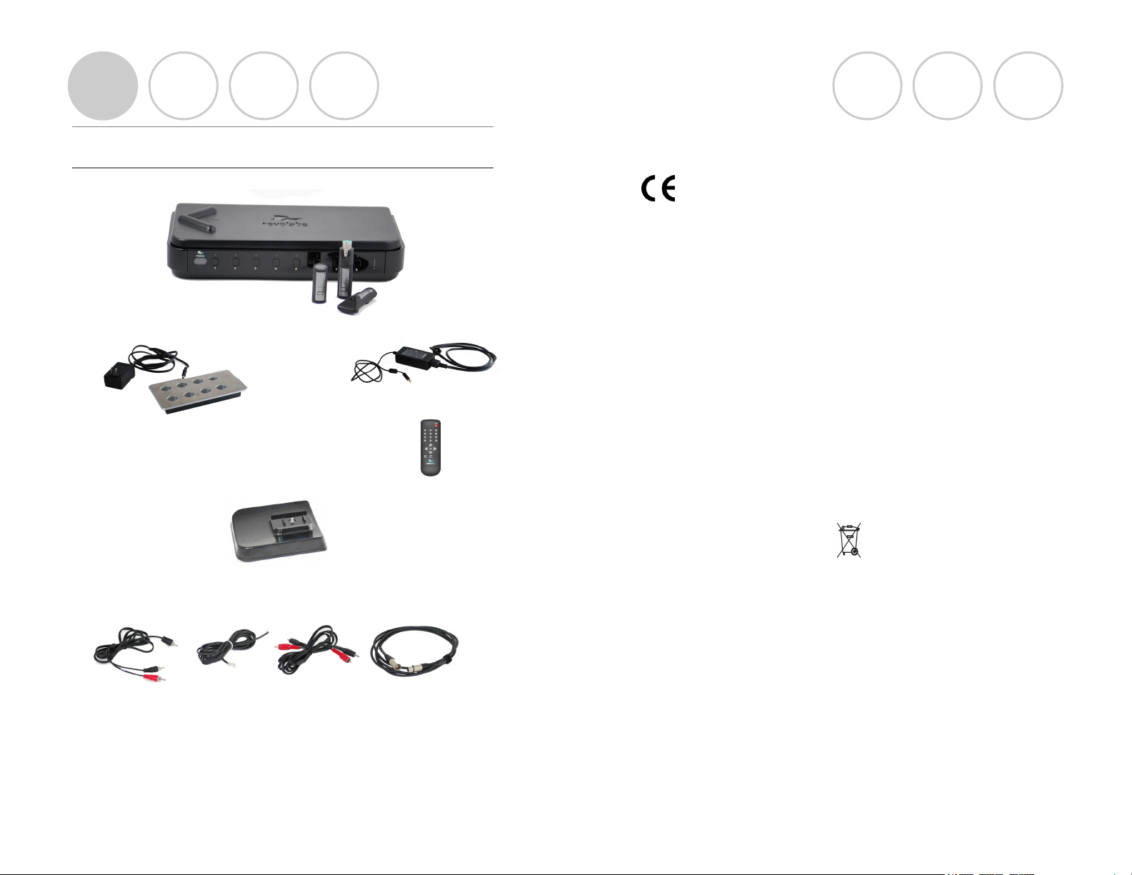
Contents of box:
Fusion Base Station and four or eight wireless microphones (any type)
Charger Base and
AC wall adapter for Charger Base
Cable A
Speakers
Fusion Base Station vertical stand
Cable B
Phone Cable
AC power adapter for Base Station
Remote Control
Cable C
RCA
Cable D
XLR
Revolabs Fusion™
EUROPEAN COMPLIANCE
This equipment has been approved in accordance with Council Directive
1999/5/EC “Radio Equipment and telecommunications Equipment.
Conformity of the Equipment with the guidelines below is attested by the CE
mark.
Model Numbers:
01-8FUSIONEU-NM-01-01 Revolabs Fusion Base Station, European
01-4FUSIONEU-NM-01-01 Revolabs Fusion Base Station, European
03-EXEMICEU-BLK-11 Revolabs Solo™ Executive Microphone
03-EXECHGEU-STD-11 Revolabs Solo™ Executive Charger
05-TBLMICEU-OM-BLK-11 Revolabs Solo™ Executive Table
Microphone Omni
05-TBLMICEU-DR-BLK-11 Revolabs Solo™ Executive Table
Microphone Cardioid
06-XLRMICEU-OM-BLK-11 Revolabs Solo™ Executive XLR
Microphone Adapter
STANDARD S TO WHICH CONFOR MITY IS DEC LARE D:
RF ETSI EN 301 406 V 1.4.1 03/2001
EMC ETSI EN 301 489-6 v1.2.1 (2002-04)
WEEE NOTIFICATION:
The Waste Electrical and Electronic Equipment (WEEE) directive (2002/96/EC)
is intended to promote recycling of electrical and electronic equipment and their
components at end of life.
2003/11/E C & 2002/95/EC “ROHS COM PLI ANCE DIRECT IVE”:
The products referenced herein are in compliance with the EU directive
2003/11/EC and EU directive 2002/95/EC.
SAFETY COMPLIANCE
TUV SUD AMERICA
Optional boxes:
Four or eight wireless microphones, Remote IR Sensor, speakers
Page 4
Page 29
Page 5
Set-Up Guide
INDUSTRY CANADA NO TICE TO USE RS
Operation is subject to the following two conditions:
(1) This device may not cause interference and
(2) This device must accept any interference, including interference that may
cause undesired operation of the device.
IC: 6455A-2FUSION8 Revolabs Fusion™ Base Station 8 microphones
IC; 6455A-2FUSION4 Revolabs Fusion™ Base Station 4 microphones
IC: 6455A-01EXEMIC Revolabs Solo™ Executive Microphone
RESTRICT ED USE WITH CE RTAIN MEDI CAL DEV ICES
Hearing Aids
Some devices may interfere with some hearing aids. In the event of such
interference, you may want to consult with your hearing aid manufacturer to
discuss alternatives.
Other Medical Devices
If you use any other personal medical device, consult the manufacturer of your
device to determine if it is adequately shielded from RF energy. Your physician
may be able to assist you in obtaining this information.
EXPORT LAW A SSU RANC ES
This product is controlled under the export regulations of the United States of
America and Canada. The Governments of the United States of America and
Canada may restrict the exportation or re-exportation of this product to
certain destinations. For further information contact the U.S. Department of
Commerce or the Canadian Department of Foreign Affairs and International
Trade. The use of wireless devices and their accessories may be prohibited or
restricted in certain areas. Always obey the laws and regulations on the use of
these products.
Revolabs Fusion™
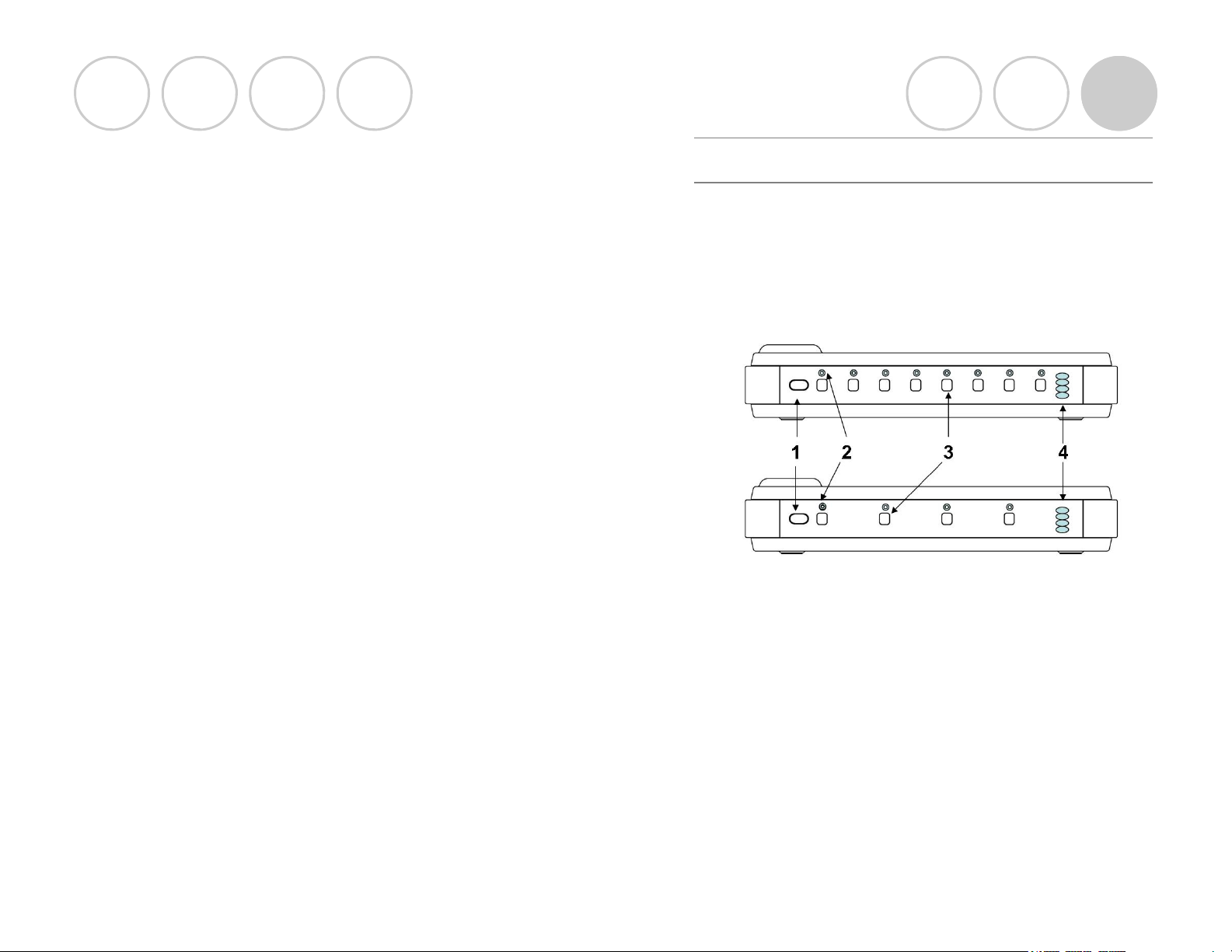
Details about the Fusion
Fusion Front Panel
The Revolabs Fusion Base Station, shown below in front and rear panel
views, manages wireless audio signal processing, and pairing between the Solo
microphones and the Fusion Base Station.
1. IR Remote receiver (if not in sight range of remote, page 22)
2. LED indicators: Displays microphone mute and pairing states
3. Pairing Push Buttons: For pairing microphones to Base
Station (page 9)
4. Power On LED/Volume indicator
Page 28
Page 5
Page 6

Set-Up Guide
Revolabs Fusion™
Fusion Back Panel
1. Power
2. 6 RCA Plugs
• AUX IN (for auxiliary input devices)
• AUX OUT
• RECORD OUT (for audio recording devices)
• ROOM OUT
• CONFERENCE IN
• CONFERENCE OUT
3. Conference Out XLR (Microphone level)
4. Network RJ 45 (Revolabs use only)
5. Telephone Line-in RJ11
6. Telephone Set-in RJ11
7. Audio Control RJ45 (Revolabs use only)
8. Programming Port: LEFT DIP Switches 1-8 (refer to page 18)
9. Programming Port: RIGHT DIP Switches 1-8 (Revolabs Use Only)
10. DB9 (Revolabs use only)
11. IR Remote DB9
NOTE: This equipment has been tested and found to comply with the limits
for a Class B digital device, pursuant to part 15 of the FCC Rules. These limits
are designed to provide reasonable protection against harmful interference in a
residential installation. This equipment generates, uses, and can radiate radio
frequency energy and, if not installed and used in accordance with the
instructions, may cause harmful interference to radio communications.
However, there is no guarantee that interference will not occur in a particular
installation. If this equipment does cause harmful interference to radio or
television reception, which can be determined by turning the equipment off and
on, the user is encouraged to try to correct the interference by one or more of
the following measures:
• Reorient or relocate the receiving antenna.
• Increase the separation between the equipment and receiver.
• Connect the equipment into an outlet on a circuit different from that to
which the receiver is connected.
• Consult the dealer or an experienced radio/TV technician for help.
Page 6
Page 27
Page 7

Set-Up Guide
Revolabs Fusion™
Safety and Regulatory Information
Please read the following information to ensure safe use of your Revolabs
system.
FCC User Information
FCC Registration Number: 0014898290
FCC ID: T5V2FUSION 8 Revolabs Fusion™ Base Station 8 microphones
FCC ID: T5V2FUSION4 Revolabs Fusion™ Base Station 4 microphones
FCC ID: T5V-01-EXEMIC Revolabs Solo™ Executive Microphone
FCC NOTICE TO U SERS
Users are not permitted to make changes or modify the equipment in any way.
Changes or modifications not expressly approved by Revolabs, Inc. could void
the user’s authority to operate the equipment. To meet FCC and Industry
Canada RF radiation exposure limits for general population (uncontrolled
exposure), a minimum of 7.9 inches (20 cm) separation distance must be
maintained between the Fusion Base Station and users' and/or nearby persons'
bodies at all times. Additionally, the Fusion Base Station must not be co-located
with any other antenna or transmitter.
This device complies with Part 15 of the FCC Rules. Operation is subject to the
following two conditions: (1) this device may not cause harmful interference, and
(2) this device must accept any interference received, including interference that
may cause undesired operation.
This product has been found to comply with the Rules of 47 CFR Part 68 of the
Federal Communications Commission and Technical Requirements For
Connection of Terminal Equipment to the Telephone Network TIA-968-A-1, A2 and A-3.
Certificate Number: US:6RMBR00BNEXIATC Date: April 14, 2006
IMPORTANT N OTE: FEDERAL COMMUNICATIO NS COMMISSION
(FCC ) RA DIATION EXPOSU RE STATEMEN T
This equipment complies with FCC radiation exposure limits for an
uncontrolled environment.
STEP 1: Fusion Set-Up
Hardware
Decide if want to place Fusion Base Station horizontally or vertically on a flat
surface. To set-up vertically, place the Fusion Base Station vertical stand on the
bottom of the Fusion unit. Tighten bolt into Fusion Base Station.
Fusion Base Station Placement
WARNING: Do not put Fusion Base Station behind metal doors.
If you are putting the Fusion Base Station into a cabinet with non-metal doors,
you need to use the Remote IR Sensor (part number 07-IRREMO-01) for
remote to work. (Refer to page 22)
Power
Plug AC power adapter power cord into the back of the Fusion Base Station and
into wall outlet.
Plug AC wall adapter into the power outlet and the other end into the
microphone Charger Base.
Place wireless microphones in the Charger Base, let charge overnight or at least
eight hours.
Indicator lights on the Base Station Charger Base and microphones should be lit,
verifying all units are operating.
NOTE: Wait (approximately 30 seconds) until the Fusion Base Station has
powered up and the status lights have stopped flashing, before continuing on
with next steps,
Page 26
Page 7
Page 8

Set-Up Guide
Revolabs Fusion™
STEP 2: Audio Conferencing
Plug Cable A (single RCA to double RCA) single RCA connector into Fusion
Base Station <Room Out> RCA port, and then plug the double RCA
connectors into the powered speakers or a powered amplifier. Plug speakers
into wall outlet.
Plug one end of Cable B, the phone line cable, into the Fusion Base Station
<Line In>, plug other end into phone jack. You may also plug a phone into the
RJ11 <Set In>, You may then dial with the remote control or the phone.
If you ordered Fusion packaged with 6 omni tabletops/2 wearable microphones
or 3 omni tabletops/1 wearable microphone, you are all set to go! Take out the
Wireless Microphones, un-mute them by pressing the mute button on the
microphone and the system is ready for a conference!
If you purchased your microphones you must first establish a connection
between your microphones to the Fusion Base Station. This is called “pairing”.
Refer to page 9.
STEP 2: Video Conferencing
You must have the audio output going from the Fusion Base station directly to
the speakers used by the video-conferencing station. Plug Cable A (single RCA
to double RCA) single RCA connector into Fusion Base Station <Room Out>
RCA port and then plug the double RCA connectors into the speakers or
monitor.
Once you have configured your video-conferencing station as shown on pages
11-17, then:
If you ordered Fusion packaged with 6 omni tabletops/2 wearable microphones
or 3 omni tabletops/1 wearable microphone. You are all set to go! Take out
the Wireless Microphones, un-mute them by pressing the mute button on the
microphone and the system is ready for a conference!
If you purchased your microphones separately, you must first establish a
connection between your microphones to the Fusion Base Station. This is
called “pairing”. Refer to page 9.
Base Station
Base Station
Base Station Base Station
LEDs
LEDs
LEDsLEDs
OFF Charging in Progress
OFF Charging Complete
OFF Microphone powered OFF or battery
RED Flashing Microphone master muted by remote
control or tabletop master mute
RED Flashing Microphone paired and muted
GREEN Flashing Microphone paired and “live”
Solid RED Pairing mode or confirmation of
OFF
or Alternating slow
GREEN and RED
GREEN Flashing Microphone low battery
RED Flashing Microphone low battery
OFF Searching for a connection, or out of
OFF Radio congestion – it is not possible to
OFF Unit is faulty. Contact your AV service
Microphone or channel not paired
radio range. The Microphone will try to
re-establish the link for about 15
minutes, and then turn off.
make a radio connection because there
are already too many nearby users, or
there is heavy radio interference.
Meaning
Meaning
MeaningMeaning
discharged
powering-down
(mic live)
(mic muted)
provider for advice.
Page 8
Page 25
Page 9

Set-Up Guide
Revolabs Fusion™
Indicator Lights
Equipment Use
Equipment Use Microphone LED
Equipment UseEquipment Use
Microphone in Charger Base Solid RED
Solid GREEN
Microphone not in Charger
Base
One RED flash
Two RED flashes
GREEN flash
Solid RED
Alternating slow
YELLOW flash alternating
YELLOW flash alternating
Alternating RED, YELLOW,
Rapid RED flashes continuing
Groups of five rapid RED
Microphone LED
Microphone LEDMicrophone LED
OFF
every 1.5 seconds
every 1.5 seconds
every 1.5 seconds
GREEN and RED
with GREEN
with two RED flashes
GREEN, YELLOW
for more than a few seconds
flashes
STEP 3: Pairing Microphones to Fusion
Base Station if Necessary
If you selected your microphones separately with the Fusion, you must first
establish a connection between your microphones to the Fusion Base Station.
This is called “pairing”.
Pairing creates a link with a unique electronic serial number between the Solo
wireless microphone and the Fusion Base Station. When the microphone and
Base Station have been previously paired, the microphone will automatically try
to connect to the Base Station whenever it is lifted from the Charger Base.
Note: Microphones in new systems must be paired to the Base Station
with each microphone assigned to a unique channel on the base unit.
Remember, microphones are always muted (flashing RED LED light) when they
are removed from the Charger Base and the MUTE button needs to be pressed
to make it “live” (flashing GREEN LED).
A microphone that is not paired will be indicated by either cycling RED-GREEN,
or RED-YELLOW-GREEN LED patterns. A Base Station LED that is not paired
to a microphone will not show any activity on the LED (make sure unit is first
powered on by observing GREEN power LED on the front panel).
When the microphone and Fusion Base Station are paired, both microphone
and channel LEDs will flash RED as microphones are removed from the Charger
Base and flash GREEN when un-muted.
To pair the microphone to the Fusion Base Station:
Turn the microphone OFF (no LED activity). If the microphone is ON, press
and hold the MUTE button for 10 seconds until the LED turns solid RED (do
not release when you hear two beeps). Release the button to turn the unit off.
(Continued on next page.)
Page 24
Page 9
Page 10

Set-Up Guide
Revolabs Fusion™
STEP 3 Continued: Pairing Microphones to
Fusion Base Station if Necessary
Place the microphone unit into pairing mode by holding the MUTE button down
for seven seconds. The LED will turn solid RED. Release the MUTE button. The
microphone is now in pairing mode.
Within one minute, push and hold the button for the desired channel on the
Base Station (refer to page 5) for seven seconds to enter into pairing mode then
release. The LED for that channel will be solid red until pairing starts, as
indicated by a quick GREEN flash, then switching to flashing RED on both the
microphone and the Base Station (muted audio). Pairing is now complete.
The Fusion Base Station has four or eight indicator LED lights (one for each
microphone) and pairing push buttons on the front panel. When the LED is
flashing GREEN or RED, that channel is active and connected to a wireless
microphone (GREEN is for live audio, RED is for muted). When the LED is OFF,
the channel is inactive (the microphone is out of range or turned off).
Hearing Assistance
Setting the Hearing Assistance Option
All Microphones Hear Audio From the Far End (default)
If an earpiece is plugged into any of the microphones, the user will hear the far
end of the audio only. DIP switch #8 is OFF (page 18).
Hear Audio From Both Far End and Within The Room
If the user needs to hear the audio from both the far end and the other
microphones within the room, he/she must use the microphone paired to
Channel 8 (refer to pairing mode page 9) and the DIP switch #8 must be set to
ON (page 18). Please note that the Room Out RCA plug will no longer
function in this mode; Aux Out will serve as Room Out.
NOTE: The Fusion system must be powered off and back on for any
DIP Switch changes to take effect.
Page 10
Page 23
Page 11

Set-Up Guide
Revolabs Fusion™
Remote IR Sensor
Setting the Remote IR Sensor Option
Front Panel IR Sensor (default)
If the Fusion Base Station is within view of the Remote Control, the front panel
IR Sensor will accept all Remote Control functions. DIP switch #7 is OFF (page
18).
Remote IR Sensor
If the Fusion Base Station is in a cabinet and behind a door (non-metal), the
front panel IR Sensor cannot work. The Remote IR Sensor cable (part number:
07-IRREMO-01) must be used to position the Fusion IR Sensor outside of the
cabinet. Plug the serial plug end into the IR Remote connector on the back
panel of the Fusion Base Station (page 9), bring IR Sensor end out of cabinet, and
secure with Velcro. then set DIP switch #7 to ON (page 18).
NOTE: The Fusion system must be powered off and back on for any
DIP Switch changes to take effect.
Configuring the Fusion with the Video
Conferencing System
The following pages have a representative sample of the most popular videoconferencing systems. If you cannot find your specific video-conferencing
station and need assistance in configuring the cables, check the additional
documentation in the FAQs or Technical Documentation sections on
www.revolabs.com , or the video-conferencing station documentation.
Page 22
Page 11
Page 12

Set-Up Guide
Polycom® Installation (Polycom VSX7000 shown for example)
This information is meant to be illustrative only. Consult your Polycom
Videoconferencing System Administrator Manual for specific instructions.
Revolabs Fusion™
Phone Auto Answer
Setting Phone Answering Mode
Answer with Remote Control (default)
To answer a phone call and begin a teleconference, the user must use the
Remote Control and press the “Call” key. DIP switch #6 is OFF (page 18).
Auto Answer
To answer a phone call and begin a teleconference, the user may use the
Remote Control and press the “Call” key or the Fusion Base Station will
automatically answer the call after two rings. DIP switch #6 is ON (page 18).
Step 1 Step 2
1. Plug the red RCA connector on one end of Cable C into Polycom videostation <Audio Out 1>, and then plug the red RCA connector on the other
end into the Fusion Base Station <Conf In>.
2. Plug the black RCA connector on one end of Cable C into Polycom videostation <Audio In>, and then plug the black RCA connector on the other end
into the Fusion Base Station <Conf Out>.
To configure the Polycom system:
Select the button from the main screen to access the System menu.
Select the System / Admin settings.
Enter the administrator password and press OK (if needed).
Select the Audio settings.
Confirm or modify the following settings:
• Midrange Speaker - OFF
• Line Input – Audio Mixer
• Echo Canceller - OFF
• Line Output – Monitor Far Site Audio
• Press OK to save changes.
Page 12
NOTE: The Fusion system must be powered off and back on for any
DIP Switch changes to take effect.
Page 21
Page 13

Set-Up Guide
Tabletop Master Mute
Setting the Mute Option
Individual Muting (default)
In the default setting, each Solo microphone will mute only itself when its mute
button on the microphone is pressed. To mute all of the microphones, press
the red MUTE button on the Remote Control; all microphones will flash red
and no individual microphone can be unmuted until the remote MUTE button is
pressed again. All microphones will return to their prior state. DIP switch #5
is OFF (page 18).
Revolabs Fusion™
Polycom® Installation (Polycom HDX9000 shown for example)
This information is meant to be illustrative only. Consult your Polycom
Videoconferencing System Administrator Manual for specific instructions.
NOTE: Requires 2 special RCA Male to 3.5mm 3 pin connectors
Revolabs Part #07-POLHDX-01.
Tabletop Microphone Master Mute
In addition to the Remote Control MUTE button muting all of the microphones,
the Solo Tabletop microphone MUTE button will also act as a master mute and
mute all active microphones. Pressing any Tabletop microphone MUTE button
or the Remote Control MUTE button will unmute all tabletop microphones.
All wearable and handheld adapter microphones in use will return to their prior
state. DIP switch #5 is ON (page 18).
NOTE: The Fusion system must be powered off and back on for any
DIP Switch changes to take effect.
Step 1 Step 2
1. Plug the 3.5mm 3 pin cable into the Polycom video-station <Audio In 1 Red>,
and then plug the RCA connector on the other end into the Fusion Base
Station <Conf Out>.
2. Plug the 3.5mm 3 pin cable into the Polycom video-station <Audio Out 1
Red>, and then plug the RCA connector on the other end into the Fusion
Base Station <Conf In>.
To
configure the Polycom HDX 9000 Series system:
:
Select the button from the main screen to access the System menu.
Select the System / Admin settings.
Enter the administrator password and press OK (if needed).
Select the Audio settings.
Confirm or modify the following settings:
• Input Type – Line Input
• Input Type Level – 50%
• Echo Canceller - OFF
• Line Output Mode – Fixed
• Line Output Level – 50%
• Press OK to save changes.
Page 20
Page 13
Page 14

Set-Up Guide
Tandberg™ Installation (Tandberg Edge 95 shown for example)
This information is meant to be illustrative only. Consult your Tandberg
Videoconferencing System Administrator Manual for the specific instructions.
Step 1 Step 2
1. Plug the black RCA connector on one end of Cable C into Tandberg videostation <Audio Out 1>, and then plug the black RCA connector on the other
end into the Fusion Base Station <Conf In>. The other RCA connector is not
used.
2. Plug one XLR connector of Cable D, XLR to XLR, into Tandberg videostation <Mic 1 Input> and the other XLR connector into the Fusion Base
Station Mic Level Output <Conf Out (Mics)>.
To configure the Tandberg system:
Select the button from the main screen to access the System menu.
Go to Audio settings
Confirm or modify the following settings:
• Input 1 - MIC
• Output 1 - ON
• Audio Leveling - OFF
• Echo Canceller - OFF
Adjust the audio Input Level if necessary.
Speak into the Revolabs microphones that are connected to the audio line inputs.
The audio meter should peak at about 5 dB.
Page 14
Revolabs Fusion™
Multiple Fusion Systems
There are two settings that must be adjusted when more than one Fusion
system is used within a 100’ (30.5 m) range: frequency and transmit power
level. These settings will enable several Fusion systems to be used near each
other, but not interfere with each other. Interference between systems can
cause occasional audio noise and signal dropouts on affected systems. Building
conditions may influence this distance.
NOTE: Even using the settings below, the 8-Microphone Fusion
System requires 40 feet (12.2 m) between systems.
Setting the Transmit Power Level for Multiple Fusion Systems
Setting the Transmit Power Level for Multiple Fusion Systems
Setting the Transmit Power Level for Multiple Fusion SystemsSetting the Transmit Power Level for Multiple Fusion Systems
In confined settings where multiple Fusion systems are used, or where audio
interference is likely, it may be necessary to reduce the transmit power levels.
The transmit power level between the microphones and Fusion Base Station can
be set to the following three levels:
• Highest power level (default) – 100 feet (30.5 m) maximum operating
distance between Microphone and Fusion Base Station DIP Switches #1 and
#2 are OFF (page 18).
• Medium power level – 30 feet (9 m) maximum operating distance between
Microphone and Fusion Base Station . DIP Switch #1 is ON and DIP
Switch #2 is OFF (page 18).
• Lowest power level – 8 feet (2.4 m) maximum operating distance between
Microphone and Fusion Base Station . DIP Switch #2 is ON and DIP Switch
#1 is OFF (page 18).
Frequency Settings
Frequency Settings
Frequency SettingsFrequency Settings
Frequency should be alternated to different frequency ranges, A and B. So an
example of five conference rooms in a row would be configured:
Conference
Conference
ConferenceConference
Room
Room
RoomRoom
Frequency
Frequency AAAA BBBB AAAA BBBB AAAA
FrequencyFrequency
To configure the Fusion to frequency mode A, Dip Switch #3 is ON and DIP
Switch #4 is OFF. Frequency mode B - Dip Switch #4 is ON and DIP Switch #3
is OFF. (page 18).
NOTE: The Fusion system must be powered off and back on for any
DIP Switch changes to take effect.
1111 2222 3333 4444 5555
Page 19
Page 15

Set-Up Guide
Programming Port: DIP Switches
Revolabs Fusion™
Tandberg™ Installation (Tandberg Profile MXP shown for
example)
The Fusion Base Station factory default settings are all OFF. The left
Programming Port (#8, page 6) is end-user configurable. Programming Port (#9,
page 6) on the right is reserved for Revolabs Use Only.
NOTE: The Fusion system must be powered off and back on for any
DIP Switch changes to take effect.
OFF
ON
1 2 3 4 5 6
Transmit Power Medium
Transmit Power Low
Frequency A Mode
Frequency B Mode
Tabletop Master Mute
Phone Auto Answer
IR Remote
Hearing Assistance
7 8
This information is meant to be illustrative only. Consult your Tandberg
Videoconferencing System Administrator Manual for the specific instructions.
Step 1 Step 2
1. Plug one XLR connector of Cable D, XLR to XLR, into Tandberg videostation <Mic 1 Input> and the other XLR connector into the Fusion Base Station
Mic Level Output <XLR>.
2. Plug the black RCA connector on one end of Cable C into Tandberg videostation <Audio Out 1>, and then plug the black RCA connector on the other end
into the Fusion Base Station <Conf In>. The other RCA connector is not used.
To configure the Tandberg system:
Select the button from the main screen to access the System menu.
Go to Audio settings
Confirm or modify the following settings:
• Input 1 - MIC
• Output 1 - ON
• Audio Leveling - OFF
• Echo Canceller and Noise Reduction (EC and NR) - OFF
Adjust the audio Input Level if necessary.
Speak into the Revolabs microphones that are connected to the audio line inputs.
The audio meter should peak at about 5 dB.
Page 18
Page 15
Page 16

Set-Up Guide
Revolabs Fusion™
Lifesize® Installation (Lifesize Team shown for example)
This information is meant to be illustrative only. Consult your Lifesize
Videoconferencing System Administrator Manual for specific instructions.
Step 1 Step 2
1. Plug the red RCA connector on one end of Cable C into Lifesize videostation <Audio Out 1>, and then plug the red RCA connector on the other
end into the Fusion Base Station <Conf In>.
2. Plug the black RCA connector on one end of Cable C into Lifesize videostation <Audio In>, and then plug the black RCA connector on the other
end into the Fusion Base Station <Conf Out>.
To configure the Lifesize system:
Select the button from the main screen to access the System menu.
Select the Administrator Preferences settings.
Enter the administrator password and press OK (if needed).
Select the Audio settings.
Confirm or modify the following settings:
• Voice Call Audio - Output
• Line Input - Enabled
• Line In to Line Out - Disabled
• Line In Acoustic Echo Canceller - Disabled
• Press OK to save changes.
Sony® Installation (Sony G70 shown for example)
This information is meant to be illustrative only. Consult your Sony
Videoconferencing System Administrator Manual for the specific instructions.
NOTE: Requires special adapter cable - XLR Female to 3.5 mm mini connector.
Part number: 07-SONYVC-01
Step 1 Step 2
1. Plug the red RCA connector on one end of Cable C into Sony videostation <Audio Out 1>, and then plug the red RCA connector on the other
end into the Fusion Base Station <Conf In>.
2. Plug one XLR connector of Cable D, XLR to XLR, into XLR Female to
3.5mm adapter cable and then to the Sony video-station <Mic 1 Input> and
the other XLR connector into the Fusion Base Station Mic Level Output
<Conf Out (Mics)>.
To configure the Sony system:
• Select the Audio settings drop down menu.
Confirm or modify the following settings:
• Input Select - MIC
• MIC Select – MIC
• Echo Canceller - OFF
• CTE – OFF
• Press SAVE to save changes.
Page 16
Page 17
 Loading...