

Page 1

1
REVOLABS FLX™ UC 1000 &
10-FLXUC1000
10-FLXUC1500
REVOLABS FLX™ UC 1500
IP & USB Conference Phone
Installation and Operation Guide
Models:
Page 2

2
© 2016 REVOLABS, INC. All rights reserved. No part of this document may be
reproduced in any form or by any means without express written permission
from Revolabs, Inc. Product specifications are subject to change without notice.
R e v o l a b s F L X U C 1 0 0 0 / F L X U C 1 5 0 0 I n s t a l l a t i o n a n d O p e r a t i o n
G u i d e
10- F L X U C 1500- EN
M a r c h 2016 ( R e v 2 . 6 .0)
Page 3
3
Online Resources
Resource
Website
Revolabs
www.revolabs.com
Revolabs FLX UC 1000
http://revolabs.com/products/productline/flx-uc-1000
Revolabs FLX UC 1500
http://revolabs.com/products/productline/flx-uc-1500
Customer Support
http://revolabs.com/support
Support by Product Line
http://revolabs.com/support/productline
Page 4

4
Contents
Online Resources ............................................................................................ 3
Contents ......................................................................................................... 4
Product Overview ............................................................................................ 7
Getting Started ............................................................................................... 9
Connecting the Device .................................................................................. 9
Connecting the Dialer .............................................................................. 10
Connecting to an IP Network for VoIP Calling ........................................... 11
Connecting to a Computer ....................................................................... 12
Connecting Extension Mics ..................................................................... 13
Component Overview.................................................................................. 14
Base Unit ................................................................................................ 14
Dialer ...................................................................................................... 15
User Interface ............................................................................................ 18
Base Unit ................................................................................................ 18
Dialer ...................................................................................................... 18
Web User Interface (Web UI) .................................................................... 31
Basic Operations ........................................................................................... 39
Dialing a Number ....................................................................................... 39
Redialing a Number .................................................................................... 39
Dialing a Contact ....................................................................................... 40
Making a call while another call is already active ........................................ 40
Answering an Incoming Call ....................................................................... 40
Ignoring an Incoming Call .......................................................................... 40
Hanging Up a Call ...................................................................................... 40
Using USB Audio on the FLX UC 1000 or FLX UC 1500 ............................. 40
Setting up a Conference Call ...................................................................... 42
Using Do Not Disturb ................................................................................. 42
Configuring the FLX UC 1000 or FLX UC 1500 for your VoIP Network ........... 43
Through the Dialer ..................................................................................... 43
Page 5

5
Through Web User Interface ....................................................................... 43
Through Provisioning Server, using Option 66 ............................................ 44
Through Provisioning Server, using Option 150 .......................................... 45
Provisioning configuration file sample......................................................... 46
Device configuration file without include files. ......................................... 46
Device configuration file with include files ............................................... 47
Advanced Operations .................................................................................... 49
802.1x ....................................................................................................... 49
Dial Plan .................................................................................................... 50
Dial Plan Overview .................................................................................. 50
Dial Plan Syntax ...................................................................................... 51
Syntax Examples ..................................................................................... 52
Dial Plan Examples: ................................................................................ 53
Device Manager ............................................................................................. 54
Third Party Applications Supported ............................................................ 54
Installation & Third Party Application Configuration................................... 54
For Windows ........................................................................................... 54
For Mac ................................................................................................... 55
For Chromebook ..................................................................................... 55
Upgrading the Device Firmware ..................................................................... 56
From the Web Interface .............................................................................. 56
From the Provisioning Server ...................................................................... 56
Compliance ................................................................................................... 57
FCC Notice to Users ................................................................................... 57
Radio and Television Interference ............................................................... 57
Industry Canada Notice to Users ................................................................ 58
Notice to European Customers ................................................................... 58
WEEE Notification ...................................................................................... 59
Appendix ...................................................................................................... 60
Call Control Functionality Details per Third Party Application .................... 60
Using Windows Computers ...................................................................... 60
Page 6

6
Using Apple Computers ........................................................................... 60
Known Issues ............................................................................................. 61
Optimal Audio Performance for Windows .................................................... 63
Troubleshooting ......................................................................................... 64
Reboot ..................................................................................................... 64
Restore Factory Defaults ......................................................................... 64
Cannot Access Web User Interface ........................................................... 64
Can’t find language menu because the device is in the wrong language ... 65
USB Audio call Answering and Hang-Up not working .............................. 65
Call Forwarding Behavior ........................................................................ 66
Tested Call Managers .................................................................................... 67
Specific Call Manager Configuration .............................................................. 68
3CX Phone System ..................................................................................... 68
Digium Asterisk BE .................................................................................... 68
Avaya IP Office ........................................................................................... 68
Broadsoft Broadworks ................................................................................ 69
Cisco Unified Communication Manager ...................................................... 69
Junction Networks OnSip Hosted PBX ....................................................... 69
Page 7
7
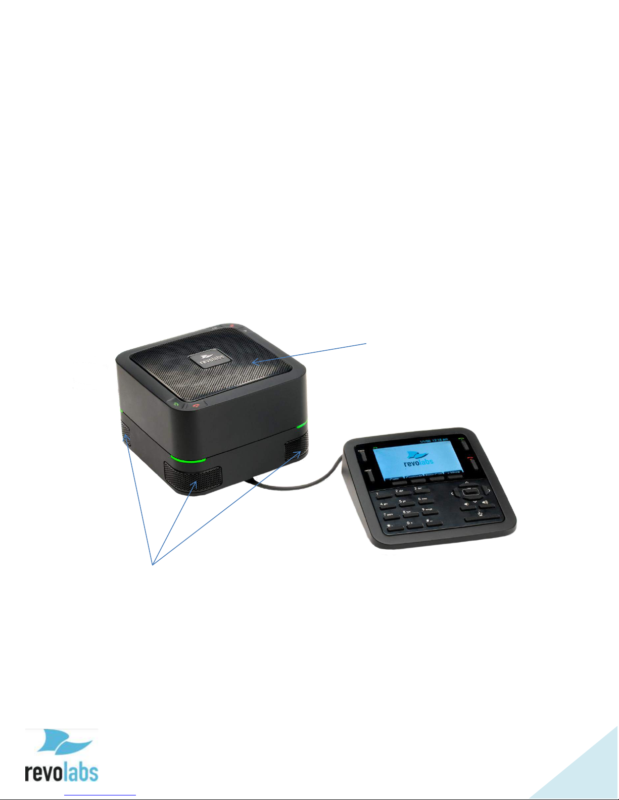
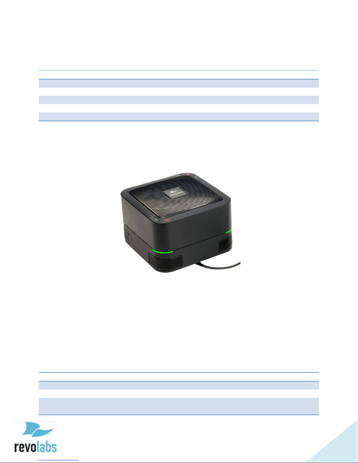
Product Overview
Speaker Elements
Directional Microphones
Thank you for choosing a FLX UC 1000 or FLX UC 1500 IP & USB Conference
Phone by Revolabs. This conference phone allows you to communicate via
your call manager and a softphone, messaging, video conferencing, or webinar
application, as well as bridge these calls together. With the FLX UC products,
call performance is built to be of the highest quality to ensure every word of the
conversation is heard.
This document covers the FLX UC 1000 and the FLX UC 1500 as configuration
of these products is similar. Where there is a difference in capabilities or
configuration, the document will highlight that explicitly.
Figure 1: FLX UC 1000 Base Unit & Dialer
Page 8
8
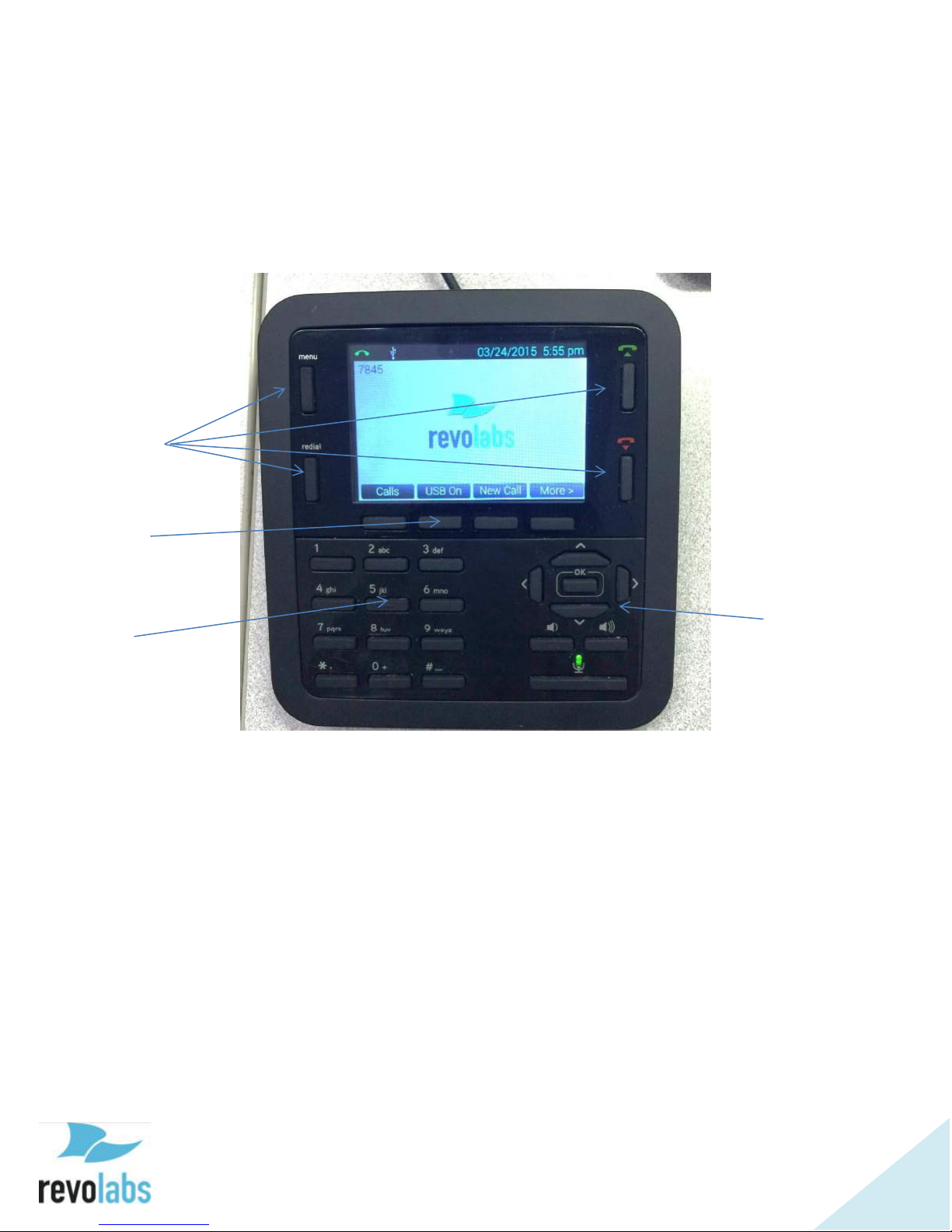
Full Color Display
Quick
Keys
Soft Keys
Keypad
Navigation &
Selection Buttons
Volume Control &
Mute
Figure 2: Keypad Detail
Page 9
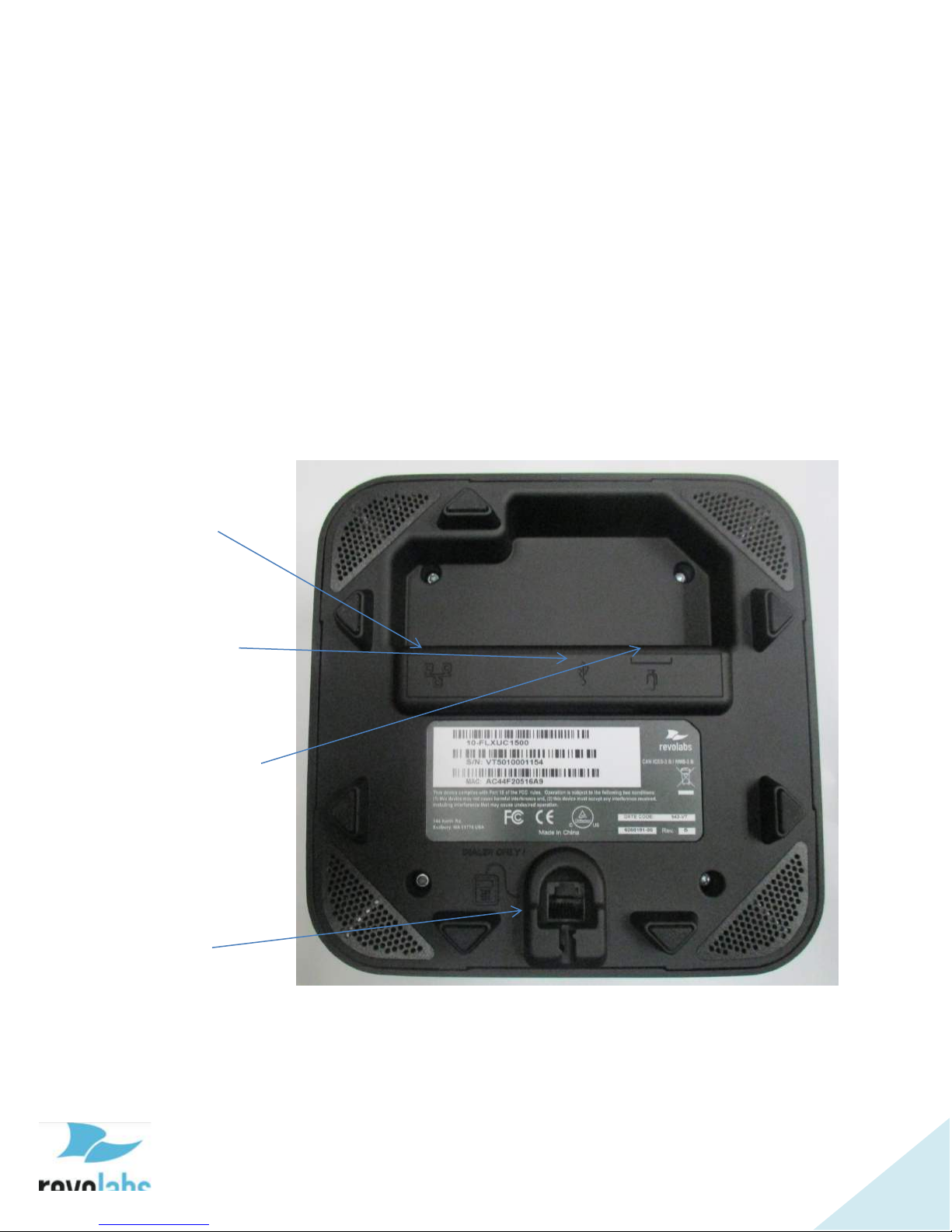
9
Getting Started
USB Connection
Ethernet
Port
USB Port
Microphone
Ports
Dialer
Port
Connecting the Device
In the box, the FLX UC 1000 includes 1 Base Unit, 1 Dialer with captive cable,
1 Ethernet Cable, and 1 USB cable.
The FLX UC 1500 includes 2 extension microphones in addition to the items
included with the FLX UC 1000.
To begin setting up the device, remove all the items from packaging.
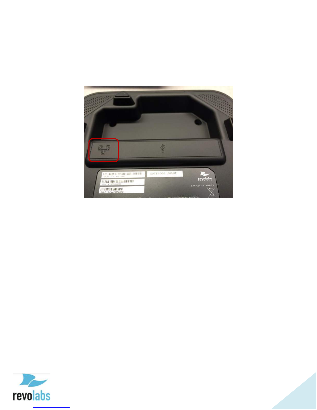
On the bottom of the base unit are connections for the Ethernet, USB, and
Dialer cables. The FLX UC 1500 has two additional connections for the
extension microphones.
Figure 3: FLX UC 1000, Connector View
Page 10
10
Ethernet
Connection
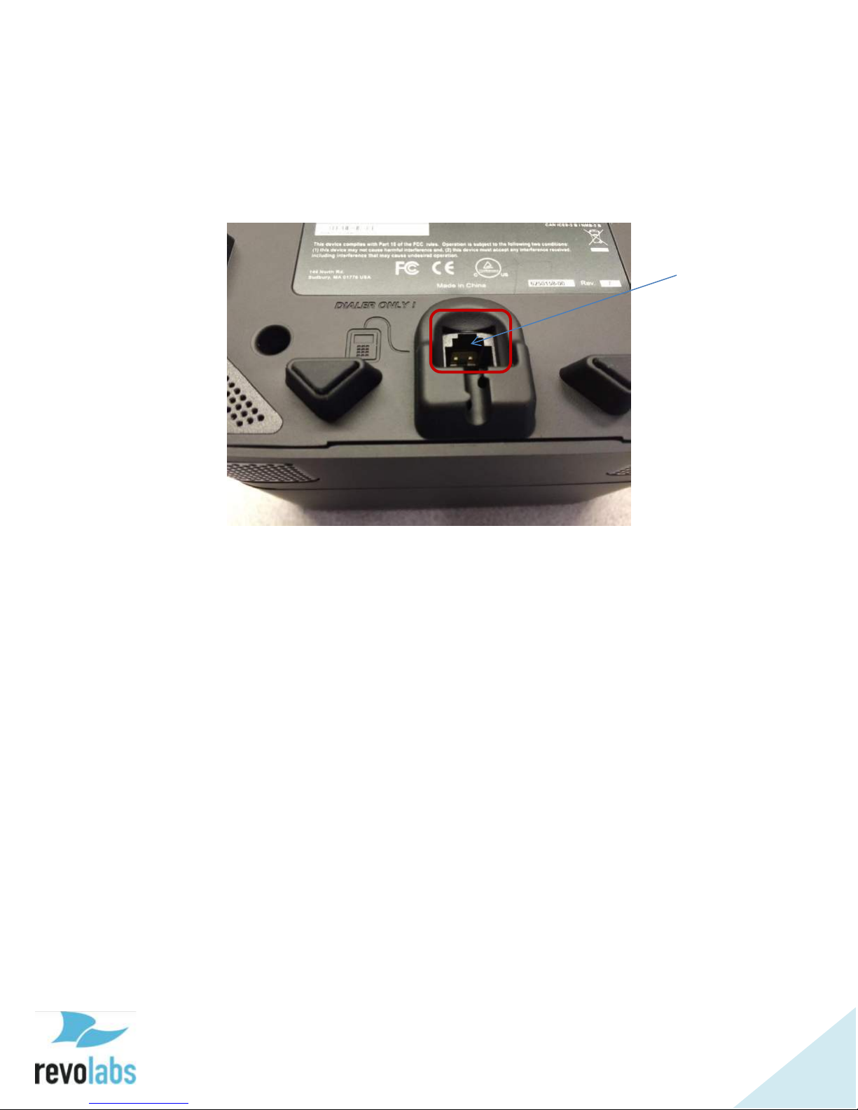
Connecting the Dialer
With the dialer in hand, use the captive cable and insert the connector into the
“Dialer Only” port on the base unit until it clicks into place.
Page 11
11
Connecting to an IP Network for VoIP Calling
The FLX UC 1000 and FLX UC 1500 are designed to be powered using 802.3af,
Power over Ethernet (PoE). If you have an Ethernet port that does not provide
PoE, a PoE Power Injector can be ordered from Revolabs to provide the device
with power.
Connect one end of the Ethernet cable into the network connection port on the
bottom of the base unit using the port highlighted in the picture above. Press
the Ethernet connector until it clicks into place. Connect the other end of the
Ethernet cable into a jack providing PoE or a PoE adapter.
If the Ethernet cable needs to be removed from the FLX UC 1000 or FLX UC
1500, be sure to depress the plastic lever on the connection to the base unit
and pull the cable out gently. Using force when removing this cable may
damage the cable and render it useless.
Once connected to a power source, the device will begin the boot up process.
The lights on the base will alternate red-orange-green-orange as the system
boots. When it is ready to use, the base will chime and the dialer will display
the home screen.
In order to place and receive VoIP calls, your FLX UC 1000 or FLX UC 1500 will
need to be registered with a call manager. See the section in this document
called “Configuring the FLX UC 1000 or FLX UC 1500 for your VoIP Network”
to register your device with a call manager. If desired, the device can be used
with a computer with or without being connected to a call manager by following
the directions in the “Connecting to a Computer” section.
Page 12
12
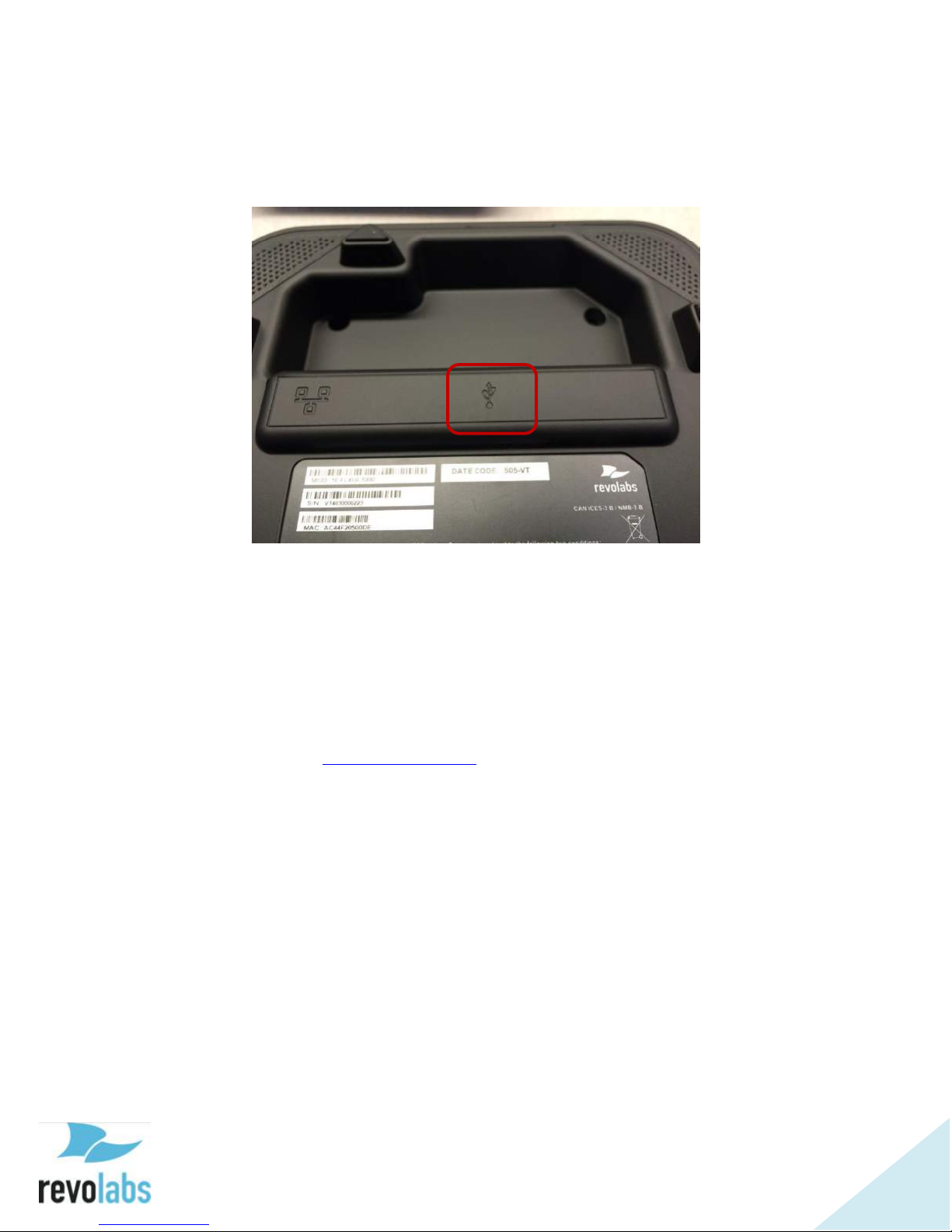
Connecting to a Computer
Using the included USB cable, connect the mini USB side of the cable into the
port identified by the icon in the figure below.
Connect the other end of the cable to the USB port on the computer running
the third party softphone, webinar, or conferencing application.
The computer may detect new driver software and install it; wait until the
install has completed before continuing. A white USB symbol will be shown on
the FLX UC 1000 or FLX UC 1500 dialer when the computer is connected.
For optimal audio performance when using a Window computers, please follow
the instructions in the appendix section. No additional configuration is
required when using Apple OS X or Chrome OS devices.
If a USB cable longer than the length of the one provided is required, an
approved USB extender should be used. The following USB extenders have
been tested and approved for use with the FLX UC 1000 or FLX UC 1500.
Please note the distance supported by each USB extender varies and is defined
by the manufacturer’s specifications:
USB Ranger 2212 Cat 5 Extender (IC2212R-05-307276) from Icron
Technologies
USB 1.1 Rover 1850 Single Port Cat 5e extender from Icron
Gefen USB 2.0 Extender
Extron USB Extender
Page 13
13
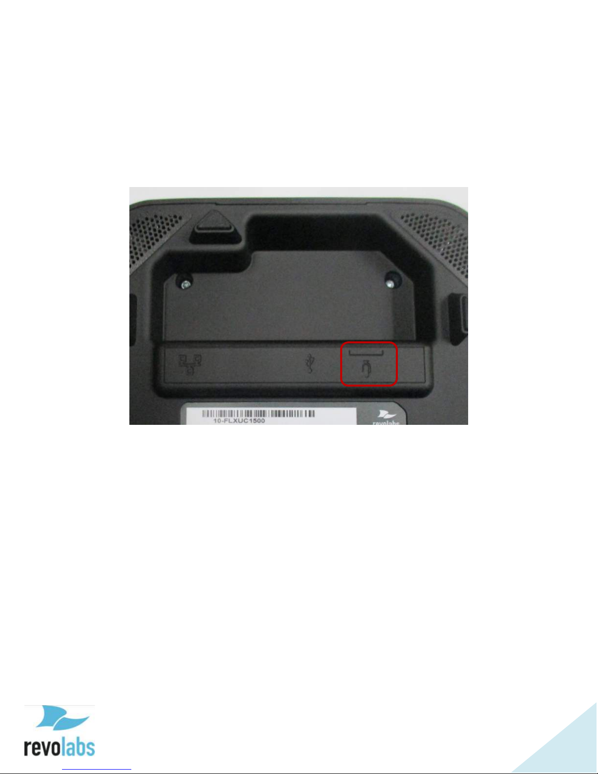
Connecting Extension Mics
The FLX UC 1500 includes two ports on the base unit to connect the two wired
extension microphones. Connect an extension microphone to one of the
microphone ports on the base unit as identified in the picture below. Repeat
for the second extension microphone.
Page 14
14
Component Overview
FLX UC 1000
FLX UC 1500
Base Unit
Base Unit
Dialer
Dialer
Ethernet Cable
Ethernet Cable
USB Cable
USB Cable
Extension Microphones (Qty. 2)
Call State
LED Color
In an active call
Green
Call Mute
Red
Idle
Configurable: Amber, Solid Green, or
No Light
Depending on the system you have purchased you will have the following:
Base Unit
In both the FLX UC 1000 and FLX UC 1500, the base unit houses the speaker
elements and four embedded microphones. On the top of the device are five
capacitive touch buttons for: volume up, volume down, mute, answer call, and
end call.
On the four corners of the base unit, LED lights display the call status. Three
different states correspond to the color of the LEDs:
Page 15
15
Ports on the bottom of the base unit are used to connect the dialer, the USB
Quick Keys
Soft Keys
Keypad
Directional
Buttons &
Volume
Control
cable, and Ethernet cable for the FLX UC 1000, and additionally two extension
microphones on the FLX UC 1500.
Dialer
The dialer has four categories of buttons:
Quick Keys: menu, redial, answer call/new call, hang up
Soft Keys: 4 keys under the color display that correspond to changing
menu options presented on the display
Keypad: for entering numbers, letters, and special characters
Directional, Volume Control and Mute: for navigating the menus on the
display, adjusting the volume and toggling mute on/off
Quick Keys
The Menu button provides access to the main menu for the FLX UC 1000 or
FLX UC 1500. When already in a menu or submenu, pressing the menu
button will return the display to the home screen.
The Redial button will redial the last number used to place an outgoing call.
Page 16

16
Answer Call/New Call and End Call buttons provide the same features as the
capacitive touch buttons on the top of the base unit. The Answer Call/New
Call Button, labeled with the green phone icon, provides the ability to answer
an incoming call. It can also be used to open the dialer menu to place a new
call.
The End Call Button, labeled with the red phone icon, provides the ability to
disconnect from an existing call.
Soft Keys
Soft keys are used to navigate through menu options, and each button
corresponds to the grey box on the display above the button. The soft keys
provide different options depending on the current dialer screen.
If a menu has more than four options the soft key on the far right will
correspond to an option for [MORE>]. Pressing this key will navigate to the next
set of menu options. In the second set of menu options the soft key on the far
right will correspond to an option for [<MORE] to allow navigation back to the
first set of menu options.
Some menus have less than four options. When this happens the space above
unused soft keys will be blank to indicate the soft keys that have no function
on the screen.
Keypad
The keypad provides access to numbers, alphabet characters, and special keys
such as *, #, space, and period which are typical on phone keypads.
When entering contacts in the FLX UC 1000 or FLX UC 1500, the keypad
buttons can be used to enter the alphanumeric values. When the button is
first pressed, the first letter shown above the button will be entered in lower
case. By pressing the button subsequent times, the character will iterate
through the other lower case letters, then the number, then upper case letters.
This sequence will repeat again from the beginning if the end of the series is
reached and the button is pressed again.
For example, the number “2” provides access to the letters a, b, and c; when
depressed multiple times, this button would iterate through the following
sequence:
a b c 2 A B C a b c 2 A B C
The button with “1” provides no other characters.
Page 17

17
The * key cycles through the following sequence:
* . , - _ ( ) @ and then repeats
The # key cycles through the following sequence
# space and then repeats (space is a “ “)
When dialing a number that begins with a plus sign (“+”), press and hold the 0
button until the “+”appears.
Directional, Volume Control & Mute
The directional buttons include left, right, up, down to navigate menu options
and “OK” for making a selection.
In general, the up and down keys are used to select different submenu options,
where the right and left keys are used to select new menus or return to the
previous menu.
Pressing the “OK” button corresponds to one of two actions on the display:
[Select] to select menus or toggle configuration items, or [Back] to exit the
menu and return to the previous parent menu.
When editing a configuration item that uses a slider bar, the left and right
arrow keys are used to change the value in the slider.
The volume control and mute buttons perform the same function as the
buttons on the base unit. The speaker volume can be increased or decreased
using the volume up and volume down buttons. The microphones on the FLX
UC 1000 and FLX UC 1500 are muted using the mute button on the dialer.
The mute/unmute button is only functional during an active call or when USB
audio is active.
Page 18

18
User Interface
Base Unit
The base unit provides volume up, volume down, mute, answer call, and hangup buttons. Mute status will be reflected on the LEDs on the four corners of
the device; during a call, these LEDs will be green when the system is unmuted
and red when the system is muted.
When not in a call, the lights can be configured for an idle color with options of
solid amber, solid green, or unlit (default). In order to change this color, an
administrator can log into the web UI or use the settings menu on the dialer to
configure the desired idle color.
For additional call control functionality, i.e. using the device buttons to hang
up and answer calls using the preferred third party softphone, webinar, or
conferencing application, refer to section in this manual on FLX UC Device
Manager.
Dialer
The display on the dialer presents a series of screens as an interface for using
the device and configuring device settings. The details of those screens are
described in this section.
Page 19
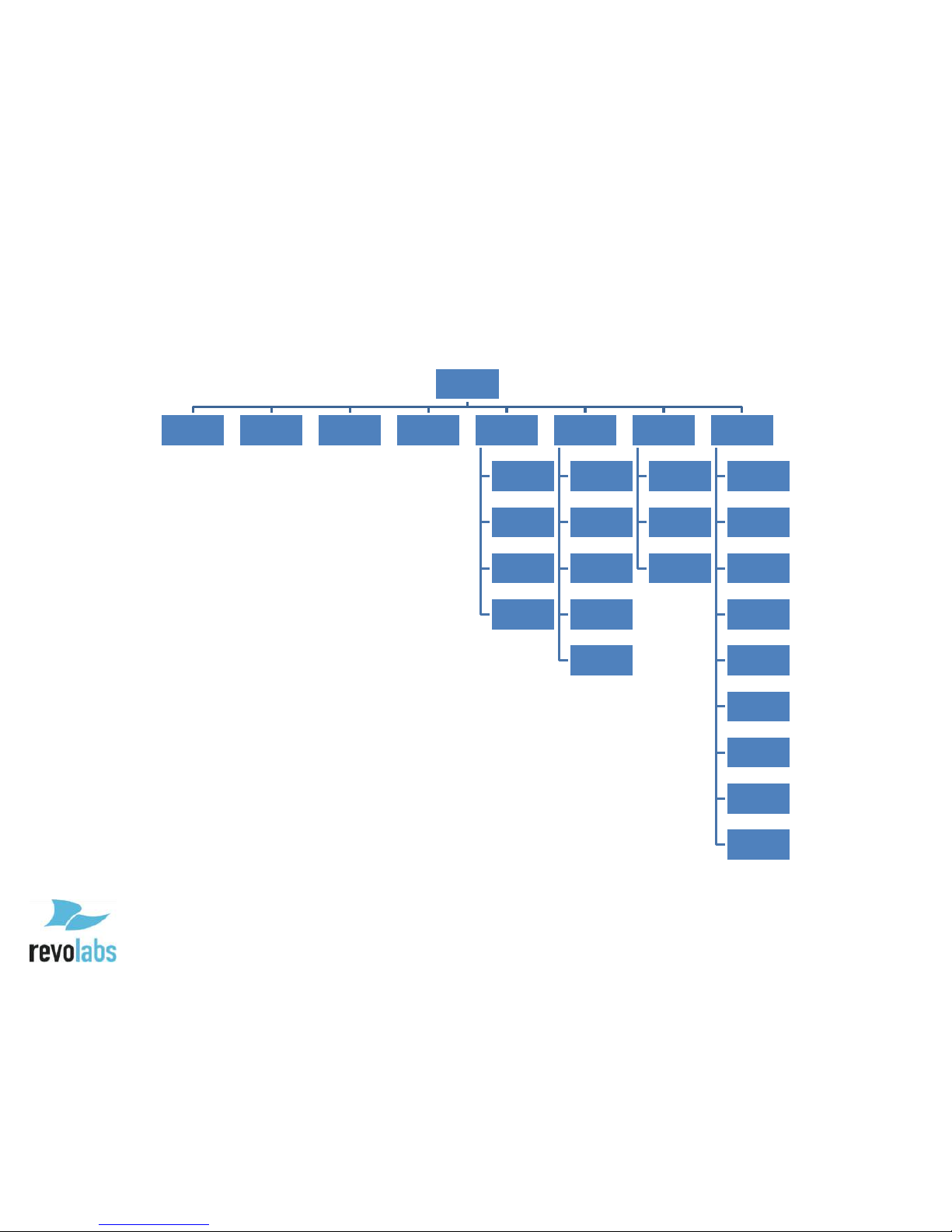
Menu Tree
Main Menu
Dialer (1) Recents (2) Contacts (3) Voicemail (4) Forwarding (5)
Always
Busy
No Answer
No Answer
Delay (seconds)
Audio (6)
Speaker Volume
Ringer Volume
Ring Selection
Speaker EQ
Advanced Audio
Settings (7)
Language
Selection
Display Settings
Admin Settings
Info (8)
Product Name
IP Address
Mac Address
Base FW
Version
Base Serial #
Dialer FW
Version
Dialer Serial #
Call 1 Statistics
Call 2 Statistics
Page 20
20
Home Screen
Quick Reference Bar
User ID
Soft Keys
When the device is powered on, the device will display the home screen. This
screen is characterized by the Revolabs logo (or customer specific logo) in the
center of the screen. On the home screen, there are three key areas to note: a
quick reference bar, information about the user ID of the device, and soft keys.
The quick reference bar provides information regarding the call status of the
system. The information available in this quick reference bar includes:
Call Icon (in Green): Displays information about call status including No
Call, Call in Progress, and Mute Indicator
USB Icon: Displays when the FLX UC 1000 or FLX UC 1500 is plugged
into a computer
Do Not Disturb (DND): Displays when the system is configured for do not
disturb.
Voice Mail Icon: Displays when a voice mail is available
Missed Call: Displays when a call has been missed
Date: Displays current date. The format is configurable in the menu or
web interface
Time: Displays current time. Time zone is configurable in the menu or
web interface
The user ID is displayed directly under the quick reference bar in the upper left
side of the screen.
The soft key menu options are available at the bottom of the screen. Refer to
the section on Soft Keys for additional details about these buttons. depending
Page 21

21
on how the USB interface has been configured, the home screen menu options
for the soft keys are as follows:
When the USB port is configured User Determined (the default)
[Calls]: Redirects to the Recent Calls menu
[USB On]: Turns USB audio on if USB audio is set to User Determined
[New Call]: Opens the Dialer menu
[More >]
After pressing [More >]
[DND]: Toggles Do Not Disturb mode
[Contacts]: Opens the Contacts menu
[< More]
When the USB port is configured Always On
[Hold]: Places the current call (USB audio) on hold
[New Call]: Opens the Dialer menu
[Conf]: Adds a new call to the existing (USB audio) call
[DND]: Toggles Do Not Disturb mode
When the USB port is configured Always Off
[Calls]: Redirects to the Recent Calls menu
[New Call]: Opens the Dialer menu
[DND]: Toggles Do Not Disturb mode
[Contacts]: Opens the Contacts menu
When the system is idle, this screen will display the Revolabs logo. The empty
screen space over the logo is where call in progress information is displayed.
VoIP Calls, of which this system supports two simultaneous calls, will take up
the top two-thirds of the screen in two bars. USB Audio, when configured for
Always On or User Determined and On, will appear as a bar on the bottom of
the screen. Up to three simultaneous calls: two VoIP and the one USB line can
be active on the FLX UC 1000 or FLX UC 1500 at one time.
The call state is indicated by the color of the bar:
Incoming Call: Yellow
Call in Progress/Active: Green
Page 22

22
On Hold: Orange
Call Ended: Red
Page 23

23
Main Menu Screen
1 - Dialer
2 - Recents
3 - Contacts
4 - Voicemail
5 - Forwarding
6 - Audio
7 - Settings
8 - Info
To access the Main Menu Screen, press the “menu” button at the top left of the
Dialer screen.
To navigate the Main Menu, use the arrow keys to move the shaded circle
around the option you wish to choose.
Alternatively, you can also press the number corresponding to the option:
Pressing the OK or Select buttons when highlighting any of these options or
pressing the number corresponding to the options will open the appropriate
submenu. Using the Back button will bring the user back to the Home Screen.
Page 24

24
Dialer Submenu
When New Call is pressed from the home screen, or 1 – Dialer from the main
menu, the following screen is shown. The keypad is used to enter a phone
number which is displayed after the word “Number:.” To dial a number that
begins with a plus sign (“+”), press and hold the 0 button until the “+”appears.
The Soft Keys available on this screen are:
Dial: Attempts to dial the number entered. The Green Call button to the
upper right of the screen can also be used to call the number (the green
Call button on the base cannot be used to attempt to dial the number –
pressing the green Call button on the base clears the number, takes the
phone off hook, and the user hears dial tone).
<x: Backspace/Deletes the last typed number
Cancel: Leaves the dialer screen and returns to the previously opened
screen
Clear: Deletes the entire number typed
Page 25

25
Recent Calls
This submenu displays the recent calls from this phone. Each call is
characterized by a name or number dialed, and the type of call: a dialed call,
received call, or a missed call. The list can be navigated by using the up and
down arrow keys. From this list, the selected call can be redialed or deleted.
This list can be sorted to display all calls, missed calls, dialed calls, or received
calls.
An individual call can be selected using the right arrow key or “OK” button,
opening an additional information submenu for that call. In the submenu, the
call has the following information under a header of name/number:
Name
Number
Time (Date and time of call)
Duration
Type of Call: Missed, Dialed, Received
From this menu, the call can be saved to contacts, deleted, or redialed.
You can use the web UI to disable changing the recent calls list from the
Dialer.
Contacts
This submenu contains the contacts list for the phone.
Page 26

26
New contacts can be added from this menu, or saved from recent calls.
The list can be traversed by using the up and down arrow keys.
An existing contact can be dialed using the dial button or the green call quick
key.
The contact can also be deleted from this menu.
An existing contact can be edited or viewed with the right arrow key, “OK”
button, or by selecting the View Soft Key.
In a contact’s submenu the Name, Work phone, Mobile phone, and Home
phone can be entered by selecting the row with the up and down arrow keys
and then editing it. (For a new contact edit mode is enabled by default, just
move to the row and start typing on the key pad.)
One of the three phone numbers can be set as the default number by selecting
the “OK” button while the number is highlighted – a green radio button icon is
shown to the right of the default number.
At the bottom of the submenu, the contact can be assigned a speed dial
number. The speed dial menu shows available speed dial numbers. To
allocate the contact to a speed dial number, hold down the button on the
keypad with the corresponding number, or highlight an available number and
press the Assign soft key.
When using speed dial to call a contact, the FLX UC 1000 or FLX UC 1500 will
use the default number for that contact.
To save a new contact, save edits to an old contact, or set a speed dial, the
contact must have a phone number set in one of the phone number fields.
Page 27

27
You can use the web UI to disable changing contacts from the Dialer.
Call Forwarding
Call forwarding can be toggled on for all calls, calls when the line is busy, and
calls not answered in a set amount of time.
When toggling on one of the forwarding options, a popup will appear asking
what phone number the calls should be forwarded to.
Wait time before an unanswered call is forwarded can be set from 2-30
seconds.
You can use the web UI to disable changing call forwarding settings from the
Dialer.
Audio
Page 28

28
“Speaker Volume” and “Ringer Volume” sliders go from 0-17. The “Ringer
Volume” slider plays a test tone for every number change. The “Speaker
Volume” slider does not.
Ring Selection opens a menu where ring tones can be selected. You can test
the ringtones before selecting in this menu by using the [Play] button at the
bottom of the screen.
Speaker EQ opens a menu where Voice Enhance, Bass Boost, or Treble Boost
can be selected.
Advanced Audio opens a menu that only has the High Pass Filter menu in it.
In the High Pass Filter menu, this filter can be set to None, 110 Hz, 140 Hz,
175 Hz, or 225 Hz.
You can use the web UI to disable changing ring selection, speaker EQ, and
advanced audio settings from the Dialer.
Voicemail
Selecting this submenu will call the mailbox assigned to the device. If no
voicemail has been configured an alert popup will appear, stating “Voice Mail
number has not been configured yet!”
Settings
There are three submenus in the Settings menu: Language Selection, Display
Settings, and Admin Settings.
Language Selection is where the language can be changed. You can use the
web UI to disable changing the language from the Dialer.
Page 29

29
Display setting has a slider for screen brightness, going from 1-15, and a menu
for Backlight Time, or how long the screen will remain lit before turning off.
Selecting “Never” for Backlight Time means the screen will not dim at all.
Admin Settings is the only menu that requires a password. The default
password is 7386, but can be changed. This is the same password to log onto
the Web UI, so changing one affects both menus.
In Admin Settings the admin password can be changed, VoIP Settings can be
set, IPv4 Settings can be set, VLAN Settings can be set, USB Settings can be
set, Date/Time settings can be changed, Access from the Web UI can be
toggled, and saving Recent Call data can be turned on or off.
Turning off Recent Calls brings up a popup asking “Do you want to clear the
recent call list?”
If “Yes” is selected, all call data on the device will be deleted, and there
will be nothing saved on the device until Recent Calls is re-enabled.
If “No” is selected, the call data is saved, but no new call data is added,
and the call data cannot be accessed until Recent Calls is re-enabled.
Further down, Idle LED Color can be set, the device can be rebooted, sections
of the system configurations can be reset one by one or all together, and the
user can log out of admin mode.
Information
This menu provides the following information about the product
Product Name: FLX UC 1000
IP Address:
Page 30

30
Mac Addr:
Base FW Version:
Dialer FW Version:
Dialer Serial #:
Extn. Mic. 1: (available on FLX UC 1500)
Extn. Mic. 2: (available on FLX UC 1500)
Call 1 Statistics
Call 2 Statistics
Page 31

31
Web User Interface (Web UI)
Once the IP address of the FLX UC 1000 or FLX UC 1500 is identified from the
Info menu on the dialer, this can be used to access the Web UI.
Using an internet browser, type the IP address for the device into the browser
address bar and press enter. This will open the login page for the product. A
password will need to be entered in order to log in to the device. If the device
has not had its password changed, the default is 7386. If you set a new
password prior to logging in to the web UI on the dialer in Admin Settings, the
new password will be required to access the menus. If desired, there is an
option to stay logged into the device on this screen underneath the password
bar. If this parameter is checked, the computer will not log out of the device
automatically, and the user will need to log out when finished with
configuration changes.
The first screen displayed after logging in will be the home screen. The device
can be configured using the Web UI by changing the parameter and pressing
submit at the upper right of the configuration page to save those changes. If
the information is not saved, the information change will need to be re-entered.
There is no auto-save.
In order to logout of the device, use the logout button on the upper right corner
of the Web UI.
Page 32

32
Home Screen
This screen is characterized by a header bar with three icons:
House Icon
Gears Icon
Tools Icon
Clicking the House icon will bring you back to the home screen from the other
pages on the site.
Hovering over the Gears and Tools icons displays the submenu options for
these menus, and allows those pages to be accessed by clicking their names.
Under the header bar, the home page contains the System Information and
Current Call information, as well as a button to restart the device.
System information provided is IP Address, Software Version, Serial Number,
and MAC Address.
Page 33

33
Settings
Admin
On the admin settings page, under the Security Settings header, the system
password can be changed, web access can be toggled, and enabling recent calls
can be toggled.
Under Dialer Restrictions Settings several features can be disabled on the
Dialer UI, including audio settings (ring selection, speaker EQ, and high pass
filter), dialer language, call forwarding, recent call list, contacts, and DND.
Under Device Settings the base’s LEDs idle setting can be set, Dialer
Brightness can be adjusted, and Dialer Backlight Timeout time can be set.
Deployment Server settings is where the deployment server can be enabled or
disabled, automatic server discovery can be toggled on or off, deployment
server address can be specified, and the provisioning time interval can be set.
The system password required format is numerical and at least four digits long.
It is the same password entered with the keypad to access the Admin Settings
on the Dialer. The default password is 7386.
Page 34

34
Disabling web access and then saving the changes will make the Web UI
unusable. Web Access must be reactivated through the Admin Setting menu
on the Dialer.
Toggling recent calls off will bring up a popup asking if the existing recent calls
list should be deleted when the submit button is clicked to save changes.
Idle LED settings change the color the lights on the base will hold while a call
is not active.
The Brightness slider goes from 1-15.
Backlight timeout sets the time the dialer will spend at full brightness before
dimming again. Setting “Never” keeps the dialer lit all the time.
Audio
Ring tone selection can be set using a dropdown menu to choose from available
ringtones. The selected Ringtone will play after “Submit” has been clicked to
save changes.
Equalizer settings available are Voice Enhance, Bass Boost, and Treble Boost.
High Pass filter can be set to None, 110Hz, 140Hz, 175Hz, or 225Hz.
USB Audio can be set to Always Enabled, Always Disabled, or User
Determined.
Audio Codecs can be configured and arranged in order of priority by dragging
and dropping them in the “enabled” box or by disabled by dragging and
dropping them into the “disabled” box.
The slider under the boxes enables the Codec ptime override to be set from 101000 milliseconds per packet.
Calls
The “Enable Message Waiting” toggle requires the device to have been set up to
support voicemail. Once a voicemail is attached to the machine, turning this
on will enable the voicemail symbol to appear on the quick-reference bar at the
top of the Dialer screen when there is a message waiting.
“Set Do Not Disturb mode” toggles do not disturb mode on the device. When
DND mode is active, incoming callers will receive a busy tone, and the device
will not ring. Missed calls will still be recorded as long as Recent Calls
information is set to be collected in Admin Settings.
Page 35

35
“Enable Auto Answer” means that the phone will answer every incoming call
without user input. This is mostly useful for testing purposes, and not
recommended for long term use.
The Voicemail number can be typed into the box below the Voicemail header.
Maximum call duration can be typed into this box, and longer calls will be cut
off. Setting a max duration of “0” or blank will make it so there is no maximum
call duration.
Enter required Dial Plan digits in the box under this header if necessary,
otherwise leave it blank. For Dial Plan instructions see the Advanced
Operations section below.
Forwarding Settings is where call forwarding is set up. After activating any of
the three forwarding options, another line will appear under the activated item
asking for the forwarding number. For the last option, “Forward on no
answer”, there will also be a slider provided to set the wait time before
forwarding between 2 and 30 seconds.
Network
Enable DHCP, if toggled off, requires a Static IP, Subnet, Default Gateway, and
DNS server to be provided in the menu that expands underneath it.
Underneath this section is the Voice VLAN option, where this option can be set
to enabled, disable, or automatic.
Authentication Settings also provides the option to enable 802.1x
authentication. See the Advanced Operations section below.
Region
Region Settings is where system language and date/time settings can be
configured.
Languages can be chosen from the first dropdown menu, while the next two
menus are for choosing the region the dial tones should emulate and the time
zone to set the time based on.
Date can be set as MM/DD/YYYY, DD/MM/YYYY, or YYYY/MM/DD, and 24
hour time can be toggled on or off. Finally the time servers can be set and
daylight savings time can be enabled or disabled.
Page 36

36
SIP
This menu is where the VoIP configuration settings are located for setting up
the FLX UC 1000 or FLX UC 1500 with the call manager. Detailed
configuration for a specific call manager is available in the Appendix.
Transport
This section allows configuration of the NAT settings for the FLX UC 1000 or
FLX UC 1500 and SRTP and RTP settings for security. Transport protocol
information for SIP messages as well as QoS configuration is available in this
page.
Page 37

37
Tools
Update
This screen allows the user to upgrade the device firmware for the FLX UC
1000 or FLX UC 1500. Download the file from the Revolabs website and either
drag this upgrade file from its folder into the box on the screen (the one labeled
“Drag and drop or click here to select a file”) or click the box to select an
upgrade file from your computer.
Once a file has been selected, clicking the “Update Firmware” button will
initiate the upgrade. When the upgrade has completed, the device will restart,
and the boot-up chime will sound.
Ensure the device is not unplugged while upgrading.
Contacts
Contacts cannot be edited or viewed through the Web UI, to edit or view your
contacts, please use the “Contacts” menu accessible through the Dialer.
From this screen, the device’s contacts can be exported as a CSV file, or an
existing file can be imported either by dragging it into the box, or clicking the
box and navigating to it on your computer, then clicking “Import Contacts”.
Configuration
Configurations can be exported or imported through this screen.
Page 38

38
System defaults can be restored in a granular way by selecting which parts of
the configuration to reset to defaults and then clicking the “Reset Defaults”
button. Restore to Factory Defaults removes the entire configuration.
Logs
On this page logs can be downloaded, and logging can be toggled between a
normal and more detailed mode.
Page 39

39
Basic Operations
Prior to making any calls on the FLX UC 1000 or FLX UC 1500 using VoIP, the
conference phone must be registered with a call manager. See Configuring the
FLX UC 1000 or FLX UC 1500 for your VoIP Network
Dialing a Number
There are two ways to dial a number from the FLX UC 1000 or FLX UC 1500
dialer.
To immediately dial a number, press the green answer button and enter the
number using the buttons on the keypad, similar to dialing on a standard
phone. If you make a mistake, you can [Clear] the number, which brings up
the dial number menu to start again, or press the Hang Up Call or the [Cancel]
soft key to terminate the call.
Alternatively, from the home screen on the Dialer, enter the “Dialer” menu
using either the [New Call] soft key along the bottom of the screen or from the
Main Menu select the “Dialer” menu arrow keys or press the number “1”. Once
in the dial number menu enter the numbers to be dialed using the keypad
buttons. The call is not initiated until the [Dial] or green answer buttons are
selected, similar to how a smartphone works. Prior to pressing [Dial] or
selecting the green answer buttons, use the [<x] button at the bottom of the
screen to delete numbers, or press the [Clear] button to empty the whole
number and start again.
To dial a number that begins with a plus sign (“+”), press and hold the 0 button
until the “+”appears.
Redialing a Number
The Redial button will redial the last number used to place an outgoing call.
To redial a number from the recent calls list, from the home screen use the
[Calls] button at the bottom of the screen, or from the Main Menu select the
“Recents” menu with the arrow keys or press the number “2”.
Select the previously used number from the Recent Calls list with the up and
down arrow keys, then press the green answer button to initiate the call, or
choose [More >] soft key and then press the [Dial] soft key at the bottom of the
screen to redial that number.
Page 40

40
Dialing a Contact
If the phone is configured for USB Always Off or USB User Determined, from
the home screen, enter the “Contacts” menu by selecting [More >] and then
[Contacts] using the soft keys at the bottom of the screen. Alternatively, from
the Main Menu, select Contacts with the arrow keys or push the number “3” on
the keypad.
To call the Default number of a contact, you can simply select the desired
contact with the up and down arrow keys and then used the [Dial] soft key at
the bottom of the screen or press the green answer buttons. To dial one of the
non-default numbers of a contact open the contact, then select the desired
number with the up and down arrow keys before using the [Dial] soft key at the
bottom of the screen or press the green answer buttons.
The default number of the contact is the one with the green radio button next
to it in that contact’s mini-menu.
Making a call while another call is already active
Select [New Call] along the bottom of the screen and dial the second number.
The first call will be put on hold and the second call will now be active. To
switch between calls, use the black outline to select the desired call with the up
or down arrow keys, and then press the [Resume] button at the bottom of the
screen. This will switch the selected call to active, and put the previous call on
hold.
Answering an Incoming Call
While on a call, answer an incoming call by hitting the green answer button on
the dialer or base.
Ignoring an Incoming Call
To ignore the incoming call, select it through the dialer and press the [Ignore]
button. Alternatively, press the red hang-up buttons on either base or the
dialer.
Hanging Up a Call
Pressing the red hang-up button will hang up on your ongoing call.
Using USB Audio on the FLX UC 1000 or FLX UC 1500
Using the Web UI or the Admin settings for USB Audio on the Dialer, configure
the system for USB Audio by selecting Always On or User Determined.
Page 41

41
If USB Audio is not to be used, select Always Off.
If User Determined is selected, turn on USB Audio from the home page of the
Dialer by selecting the [USB On] button at the bottom of the screen.
If audio from the computer isn’t playing through the FLX UC 1000 or FLX UC
1500, verify the volume settings and speaker mute settings on the PC to ensure
the system is not muted and the volume level is not at its minimum. Verify that
the FLX UC 1000 or FLX UC 1500 is chosen as the Default Audio device in the
PC Sounds menu, and that USB is on via the dialer. This should resolve any
issues with the audio playing through the device.
For additional call control (hang-up and answer) with Third Party Conferencing
Applications, please refer to the section on the FLX UC Device Manager on how
to use this software.
Page 42

42
Setting up a Conference Call
The FLX UC 1000 or FLX UC 1500 can have two simultaneous VoIP calls and
the USB audio line active at the same time. Any combination of these calls can
be joined into a conference.
To set up a conference call when no calls are active, simply initiate the first
call, then press the [Conf] button at the bottom of the screen and dial a second
call. Both calls will now be active at once and in a conference call with one
another.
To set up a conference call when more than one call is up on the screen, select
one call and make it active (not on hold). Then select the second call you wish
to include in the conference, and hit the [Join] button at the bottom of the
screen. This will create a conference call. The third call can be included in the
same conference call by selecting it and hitting [Join] again.
To separate the conference call, hit the [Split] button at the bottom of the
screen while selecting the conference call. This will split the conference and
put all the calls on hold. Select the call you wish to switch to, and press
[Resume] to activate it.
NOTE: Hanging up on a conference call you are hosting will hang up on
the connection between the three calls. The conference will not continue
after you leave. Hanging up on a conference you called into will only
remove you from the conference, not affect the other callers.
The FLX UC 1000 and FLX UC 1500 support a maximum of three lines for
incoming and outgoing calls. Even if the three calls are all in one conference,
more calls cannot be made through the unit. Call forwarding can be set up to
forward a caller who calls in while all three lines are busy.
Using Do Not Disturb
When Do Not Disturb mode is active, incoming calls will be received, but will
not ring the device. On the far end, the user calling the FLX UC 1000/FLX UC
1500 will receive a busy tone, or if call forwarding is configured, will be
redirected to the call forwarding number. This feature can be configured using
the dialer or the web UI.
Page 43

43
Configuring the FLX UC 1000 or FLX UC 1500 for
your VoIP Network
This section will provide details of how to configure the device to connect to a
call manager. The information provided here is general to any call manager,
and provides the details of how to access the configuration settings on the FLX
UC 1000 or FLX UC 1500 to enter in the specific call manager information.
Detailed configuration for specific call managers, including the mappings of
fields, is provided in the appendix of this manual.
There are three methods with which you can configure the FLX UC 1000 or
FLX UC 1500 to connect to the VoIP network – using the dialer, from the Web
UI, or using a provisioning server with DHCP Option 66 or 150 as described
below.
Through the Dialer
Access the Main Menu, Settings, Admin Settings, VoIP Settings from the Dialer.
The default password to Admin Settings is 7386. If you’ve changed the
password to access the Web UI, the same password applies to the Admin
Settings menu.
Select each configuration item and use the [Edit] button at the bottom of the
screen to edit the item. After filling out the necessary information, hit the
[Apply] button to save the changes.
Return to the “Admin Settings” menu and scroll down to option 9, “Reboot”.
Rebooting the device will apply the changes.
Through Web User Interface
Navigate to the SIP Settings Menu from the Gears Icon on the Home Screen.
Fill out the configuration details, then hit the “Submit” button hovering over
the top right of the screen to save your changes.
Reboot is not required.
Page 44

44
Through Provisioning Server, using Option 66
A sample configuration file is available in the section “Provisioning
configuration file sample.”
1. Configure the TFTP server name into the DHCP server option 66 string.
2. Upload the configuration file with the FLX UC 1000 or FLX UC 1500
firmware bundle onto the TFTP server identified by the DHCP server option
66 string. The device configuration file must be named with the FLX UC
1000 or FLX UC 1500’s mac address.
3. When provisioning through HTTP, the option 66 string configured on the
DHCP server should be: http://<server address>
Configuration files and firmware files should be placed under http server
document root directory.
4. When provisioning through FTP, the option 66 string specified on the DHCP
server should be: ftp://<server
address>/user=”<username>”&pass=”<password>”, where <username> and
<password> should be replaced by the FTP server username and password
respectively.
Configuration file and firmware files should be loaded to the FTP shared
folder where the <username> login will be prompted to.
5. No reboot of the system is required. On successful configuration, the phone
screen will display the phone number associated with the line.
Page 45

45
Through Provisioning Server, using Option 150
A sample configuration file is available in the section “Provisioning
configuration file sample.”
1. Configure the TFTP server addresses into the DHCP server option 150,
depending on the DHCP server type, the TFTP server addresses could be
specified by various syntax rules, for instance, on Cisco ASA Firewall
DHCP server, option 150 can be configured through following CLI
command,
dhcpd option 150 ip <server ip1> <server ip2>
while on Redhat ISC DHCP server, the option 150 should be declared in
this manner in the dhcpd.conf,
option tftp-server-name <server ip1> ,<server ip2>;
Please refer to your DHCP server user guide/instructions to ensure the
option 150 is properly configured.
2. Upload the configuration file with the UC 1000 firmware bundle onto the
TFTP server identified by the DHCP server option 150 string. The device
configuration file must be named with the phone mac address.
3. No reboot of the system is required. On successful configuration, the
phone screen will display the phone number associated with the line.
Page 46

46
Provisioning configuration file sample
The provisioning file is in xml format. The “config” tag contains all
configuration settings that pertain to the device, while the “firmware” tag
includes the latest firmware version and firmware file name.
Device configuration file without include files.
Filename: F0DEF1A064E6.xml (this is the MAC address of the device)
<provisioning>
<firmware version="2.6.0.294">FLX-UC-1500-2-6-0-294.bundle</firmware>
<config display.backlight-time="3" display.brightness="7" net.dot1x-cert-path=""
net.dot1x-anonymous-identity="" net.dot1x-password="" net.dot1x-identity=""
net.dot1x-auth-method="MD5" net.dot1x-enabled="0" net.ntp4="3.pool.ntp.org"
net.ntp3="2.pool.ntp.org" net.ntp2="1.pool.ntp.org" net.ntp1="0.pool.ntp.org"
net.vlan-id="" net.vlan="2" net.dns2="" net.dns1="" net.gateway="" net.subnet=""
net.ip="" net.dhcp="1" sys.ui-mask="0" sys.provisioning-interval="1440" sys.ledbehavior="0" sys.recent-call-enabled="1" sys.dst-end-rules="11:1:1:2" sys.dst-startrules="3:2:1:2" sys.dst-enabled="1" sys.time-zone="13" sys.twenty-four-hourtime="0" sys.date-format="MM/DD/YYYY" sys.region="23" sys.language="1" sys.webenabled="1" audio.usb-audio="3" audio.low-pass-filter="0" audio.eq="1" audio.ringtone="0" audio.ringer-volume="7" audio.speaker-volume="7" voip.do-not-disturb="0"
voip.noanswer-delay="4" voip.noanswer-forwarding-num="" voip.noanswerforwarding="0" voip.busy-forwarding-num="" voip.busy-forwarding="0" voip.alwaysforwarding-num="" voip.always-forwarding="0" voip.mwi="0" voip.duration="0"
voip.auto-answer="0" voip.ptime="20" voip.codec5="5" voip.codec4="4"
voip.codec3="3" voip.codec2="2" voip.codec1="1" voip.set-qos="0" voip.turn-tcp="0"
voip.turn-passwd="" voip.turn-user="" voip.turn-srv="" voip.use-turn="0" voip.ice-nortcp="0" voip.ice-max-hosts="5" voip.ice-regular="1" voip.use-ice="0" voip.stunsrv="" voip.local-port="5060" voip.udp-tcp-selection="0" voip.rtp-port="4000"
voip.use-srtp="0" voip.vm-number="" voip.media-onhold-method="0" voip.dtmfmethod="0" voip.min-size="0" voip.allow-strict="0" voip.no-refer-sub="0" voip.autoupdate-nat="1" voip.use-100rel="0" voip.timer-min-se="90" voip.timer-se="1800"
voip.use-timer="1" voip.rereg-delay="300" voip.reg-timeout="60" voip.realm="*"
voip.reg-use-proxy="0" voip.proxy="" voip.registrar-backup=""
voip.registrar="200.200.210.240"/>
</provisioning>
Page 47

47
Device configuration file with include files
Provisioning files can include references to other provisioning files. This feature
is useful when you have settings that are common across many systems in
your organization. For example, you could create “include” files at the
enterprise level and at the department level, which would simply be referenced
by name in the individual system provisioning files. Below are sample files that
follow this scheme, starting with a device file that includes both an
enterprise.xml file and a department.xml file.
Device configuration file
Filename: F0DEF1A064E6.xml (this is the MAC address of the device)
<provisioning include="enterprise.xml, department.xml">
<config voip.id="test" voip.name="test" voip.user="test" voip.password="test" />
</provisioning>
Include files
Filename: enterprise.xml
<provisioning>
<firmware version="2.6.0.294">FLX-UC-1500-2-6-0-294.bundle</firmware>
<config voip.registrar="200.200.210.240" voip.registrar-backup=""/>
</provisioning>
Filename: department.xml
<provisioning>
<config display.backlight-time="3" display.brightness="7" net.dot1x-cert-path=""
net.dot1x-anonymous-identity="" net.dot1x-password="" net.dot1x-identity=""
net.dot1x-auth-method="MD5" net.dot1x-enabled="0" net.ntp4="3.pool.ntp.org"
net.ntp3="2.pool.ntp.org" net.ntp2="1.pool.ntp.org" net.ntp1="0.pool.ntp.org"
net.vlan-id="" net.vlan="2" net.dns2="" net.dns1="" net.gateway="" net.subnet=""
net.ip="" net.dhcp="1" sys.ui-mask="0" sys.provisioning-interval="1440" sys.ledbehavior="0" sys.recent-call-enabled="1" sys.dst-end-rules="11:1:1:2" sys.dst-startrules="3:2:1:2" sys.dst-enabled="1" sys.time-zone="13" sys.twenty-four-hourtime="0" sys.date-format="MM/DD/YYYY" sys.region="23" sys.language="1" sys.webenabled="1" audio.usb-audio="3" audio.low-pass-filter="0" audio.eq="1" audio.ringtone="0" audio.ringer-volume="7" audio.speaker-volume="7" voip.do-not-disturb="0"
voip.noanswer-delay="4" voip.noanswer-forwarding-num="" voip.noanswerforwarding="0" voip.busy-forwarding-num="" voip.busy-forwarding="0" voip.always-
Page 48

48
forwarding-num="" voip.always-forwarding="0" voip.mwi="0" voip.duration="0"
voip.auto-answer="0" voip.ptime="20" voip.codec5="5" voip.codec4="4"
voip.codec3="3" voip.codec2="2" voip.codec1="1" voip.set-qos="0" voip.turn-tcp="0"
voip.turn-passwd="" voip.turn-user="" voip.turn-srv="" voip.use-turn="0" voip.ice-nortcp="0" voip.ice-max-hosts="5" voip.ice-regular="1" voip.use-ice="0" voip.stunsrv="" voip.local-port="5060" voip.udp-tcp-selection="0" voip.rtp-port="4000"
voip.use-srtp="0" voip.vm-number="" voip.media-onhold-method="0" voip.dtmfmethod="0" voip.min-size="0" voip.allow-strict="0" voip.no-refer-sub="0" voip.autoupdate-nat="1" voip.use-100rel="0" voip.timer-min-se="90" voip.timer-se="1800"
voip.use-timer="1" voip.rereg-delay="300" voip.reg-timeout="60" voip.realm="*"
voip.reg-use-proxy="0" voip.proxy=""/>
</provisioning>
Page 49

49
Advanced Operations
802.1x
The FLX UC 1000 and FLX UC 1500 support 802.1x authentication.
Log into the Web UI, and Enable the 802.1x setting for the device. Select the
802.1x authentication type and specify the required credentials depending on
whether the network is using MD5 authentication or Protected EAP (Protected
Extensible Authentication Protocol).
The server-side public key certificate will need to be installed on the FLX UC
1000 or 1500. A username and password are needed to complete the
authentication process.
Page 50

50
Dial Plan
The FLX UC 1000 and FLX UC 1500 support the use of a dial plan to make
calls.
Dial Plan Overview
A dial plan serves several purposes. In legacy mode, it can be used to trigger
when the accumulated digits are passed on to stack (a "match"). In legacy and
block mode it can be used to remove or replace digits, ie append a '9' as a
prefix to access an outside line (a "match"). It can be used to reject calls to
specific numbers, ie 900xxxxxxx calls. In a typical PBX configuration the reject
is done by a dial plan in the PBX, but reject was simple enough to include in
the phone dial plan.
The dial plan is generic enough that it is used for both "legacy dialing mode"
and "block dialing mode". When a digit string is passed to the dial plan check
function, the function returns "no match", "match" or "reject". If "reject" is
returned, the dial string will NOT be sent to the SIP stack and the call manager
will play a busy tone out and report "failed" to the core.
If a dial plan is not set, dialing complete in legacy mode is triggered by a
timeout at which point the accumulated digit string is passed to the SIP stack.
For block mode, the digit string is passed directly to the SIP stack.
If a dial plan is set up, dialing complete in legacy mode is triggered by either a
"match" or "reject" from the dial plan check or a timeout. For block mode, the
string is passed to the dial plan check. Only a "reject" will cause it NOT to be
dialed - both "match" and "no match" results in the string being passed to the
SIP stack to dial.
Page 51

51
Dial Plan Syntax
Dial plans consist of a series of dial digits (0..9, *, #) and modifiers ('x', '[]', '.',
'<:>', ',', '!', '^', '{}') separated by '|'
Modifier defines:
'x' is a wildcard to match any numeric digit ('0' .. '9')
'[]' is a range
[389] means '3' or '8' or '9'
[3-9] means '3' or '4' or ... or '8' or '9'
'.' means repeat i.e. "01." matches "0", "01", "011", "0111", etc.
'<:>' is for substitution: '<' dialed subsequence ':' transmitted subsequence
'>'
"<8:1650>xxxxxxx" would match "85551212" and dial "16505551212"
note: Polycom uses RRR to replace i.e. R9R600R replaces 9 with 600
','is to generate inter-sequence tones: "9,1xxxxxxxxxx" sounds dial tone after
the user presses '9' until '1' is pressed.
'!' is used to reject a sequence by placing it at the end of the sequence
"1900xxxxxxx!" will reject 900 area code numbers
'^' is used to exclude digits in the set of the range []
Page 52

52
examples:
[^15] includes 0, 2, 3, 4, 6, 7, 8, 9 i.e. [02346789]
[^2-4] includes 0, 1, 5, 6, 7, 8, 9 i.e. [0156789] */
The above modifiers are part of "DRegex" as defined in RFC4730.
Syntax Examples
The following examples shows the semantics of the <:> syntax:
• <9:>xxxxxxx—Remove 9 at the beginning of the dialed number
— For example, if a customer dials 914539400, the first 9 is removed when
the call is placed.
• <:604>xxxxxxx—Prepend 604 to all seven digit numbers
— For example, if a customer dials 4539400, 604 is added to the front of the
number, so a call to 6044539400 is placed.
• <9:604>xxxxxxx—Replaces 9 with 604
• <999:911>—Convert 999 to 911
• xx<601:600>xx—When applied on 1160122 gives 1160022
• x<60x:600>xxxxxxx —Any 60x will be replaced with 600 in the middle of the
dialed number that matches
— For example, if a customer dials 16092345678, a call is placed to
16002345678.
Page 53

53
Dial Plan Examples:
This dial plan accepts only US−style 1 + area−code + local−number, with no
restrictions on the area code and number:
• 1 xxx xxxxxxx
This also allows seven−digit US−style dialing, and automatically inserts a 1 +
212 (local area code) in the transmitted number:
• 1 xxx xxxxxxx | <:1212> xxxxxxx
For an office environment, the following plan requires a user to dial 8 as a
prefix for local calls and 9 as a prefix for long distance. Neither prefix is
transmitted when initiating the call.
• <9:>1 xxx xxxxxxx |<8:1212>xxxxxxx
This allows US−style long distance, but blocks 9xx area codes:
• 1 [2-8]xx [2-9]xxxxxx
This allows arbitrary long distance dialing, but explicitly blocks the 947 area
code:
• 1 947 xxxxxxx ! | 1 xxx xxxxxxx
The following allows only US−style 1 + area−code + local−number, but disallows
area codes and local numbers starting with 0 or 1. It also allows 411, 911, and
operator calls (0):
• 0 | [49]xx | 1 [2-9]xx [2-9]xxxxxx
Page 54

54
Device Manager
The FLX UC 500 has native support for the volume, mute and call controls for
a number of softphones, conferencing or webinar applications. Where native
support is provided, no additional software needs to be loaded on the PC, Mac
or Chromebook device. The current list of natively supported applications can
be found of the Revolabs product support webpage:
FLX UC 1000: http://revolabs.com/support/product-line/uc-1000
FLX UC 1500: http://revolabs.com/support/product-line/uc-1500
This application provides an interface for easy access to softphone controls,
configuration for a variety of softphones, conferencing, or webinar applications,
configuration of application specific commands for answer, reject, and hang up
support directly from the FLX UC 1000 or FLX UC 1500, and configuration for
launching upon windows start-up.
Third Party Applications Supported
For a list of currently supported third-party applications and versions, see the
Revolabs product support webpage:
• FLX UC 1000: http://revolabs.com/support/product-line/uc-1000
FLX UC 1500: http://revolabs.com/support/product-line/uc-1500
Installation & Third Party Application Configuration
For Windows
1. Download the firmware bundle from the product support webpage.
FLX UC 1000: http://revolabs.com/support/product-line/uc-1000
FLX UC 1500: http://revolabs.com/support/product-line/uc-1500
Double click the set up file in the folder to install the application on your
PC.
2. Navigate to Start > All Programs > Revolabs > FLX UC Device Manager and
open the application.
3. Connect the device to the PC. Device drivers should be installed when the
unit is connected to the computer.
Page 55

55
4. Click on Settings and select the application you want to use from the drop
down menu.
a. If you are using Skype, click Configure to bring up a menu allowing
application-specific configuration of the hot keys for hang-up and
answer.
b. For all other softphone applications, click OK.
Note: Softphone and device status are displayed in FLX UC Device Manager
Home Screen.
For Mac
1. Download the firmware bundle from the product suppot webpage.
FLX UC 1000: http://revolabs.com/support/product-line/uc-1000
FLX UC 1500: http://revolabs.com/support/product-line/uc-1500
2. Double click on the .dmg file.
3. When prompted, drag the FLX UC Device Manager to the Applications
folder.
4. Connect the device to the computer. Device drivers should be installed
when the unit is connected.
5. Click on “Preferences…” and select the application from the drop down
menu that you plan to use.
For Chromebook
1. Obtain the Chrome version of the Device Manager from Google’s Chrome
Web Store: https://chrome.google.com/webstore/category/apps
2. Search for the application by company (“Revolabs”) or by product name
(“FLX UC 1000” or “FLX UC 1500”).
3. Follow the instructions provided through the app store to install the Chrome
version of the Device manager.
Page 56

56
Upgrading the Device Firmware
From the Web Interface
Refer to this section in the manual to upgrade the device firmware via the web
UI.
From the Provisioning Server
Refer to this section in the manual to upgrade the device using DHCP Option
66 or 150.
Page 57

57
Compliance
FCC Notice to Users
This device complies with Part 15 of the FCC Rules. Operation is subject to the
following two conditions: (1) this device may not cause harmful interference,
and (2) this device must accept any interference received, including
interference that may cause undesired operation.
Users are not permitted to make changes or modify the equipment in any way.
Changes or modifications not expressly approved by Revolabs, Inc. could void
your authority to operate this equipment under Federal Communications
Commission’s rules.
Radio and Television Interference
This equipment has been tested and found to comply with the limits for a Class
B digital device, pursuant to Part 15 of the FCC rules. These limits are
designed to provide reasonable protection against harmful interference in a
residential installation. This equipment generates, uses and can radiate radio
frequency energy and, if not installed and used in accordance with the
instructions, may cause harmful interference to radio communications.
However, there is no guarantee that interference will not occur in a particular
installation. If this equipment does cause harmful interference to radio or
television reception, which can be determined by turning the equipment off and
on, the user is encouraged to try to correct the interference by one or more of
the following measures:
Reorient or relocate the receiving antenna.
Increase the separation between the equipment and the receiver.
Connect the equipment into an outlet on a circuit different from that to
which the receiver is connected.
Consult the dealer or an experienced radio/TV technician for help.
You may also find helpful the following booklet, prepared by the FCC: “How to
Identify and Resolve Radio-TV Interference Problems.” This booklet is available
from the U.S. Government Printing Office, Washington D.C. 20402
Page 58

58
Industry Canada Notice to Users
Model Number:
Description:
10-FLXUC1000
FLX UC 1000
10-FLXUC1500
FLX UC 1500
Operation is subject to the following two conditions:
1. This device may not cause interference and
2. This device must accept any interference, including interference that may
cause undesired operation of the device
Le présent appareil est conforme aux CNR d’Industrie Canada applicables aux
appareils radio exempts de licence. L’exploitation est autorisée aux deux
conditions suivantes : (1) l’appareil ne doit pas produire de brouillage, et (2)
l’utilisateur de l’appareil doit accepter tout brouillage radioélectrique subi,
même si le brouillage est susceptible d’en compromettre le fonctionnement.
Notice to European Customers
Revolabs, Inc.
190, High Street,
Tonbridge, Kent,
TN9 1BE,
UK.
Declare that for the hereinafter mentioned product model numbers, the
presumption of conformity with the applicable essential requirements has been
approved in accordance with the Electromagnetic Compatibility (EMC) Directive
2004/108/EC, and RoHS II Directive 2011/65/EU.
Any unauthorized modification of the products voids this Declaration.
For a copy of the original signed declaration of conformity, please contact
Revolabs at the above address.
Page 59

59
WEEE Notification
The Waste Electrical and Electronic Equipment (WEEE) directive (2012/19/EU)
is intended to promote recycling of electrical and electronic equipment and
their components at end of life.
According to the requirement of the WEEE legislation the following user
information is provided to customers for all branded Revolabs products subject
to the WEEE directive.
“The symbol on the product or its packaging indicates that this product must
not be disposed of with your other household waste. Instead, it is your
responsibility to dispose of your waste equipment by handing it over to a
designated collection point for the recycling of waste electrical and electronic
equipment. The separate collection and recycling of your waste equipment at
the time of disposal will help conserve natural resources and ensure that it is
recycled in a manner that protects human health and the environment. For
more information about where you can drop off your waste for recycling, please
contact your local authority, or where you purchased your product.”
Page 60

60
Appendix
Application
Off Hook Key
On Hook Key
Broadsoft UC-One
Answer
Hang-up, Reject
Cisco IP Communicator
Answer, Redial
Hang-up
Cisco Jabber
Answer
Hang-up, Reject
GoToMeeting
N/A
End Meeting
Microsoft Lync
Answer
Hang-up, Reject
Skype
Answer
Hang-up, Reject
Vidyo
N/A
End Meeting
WebEx
N/A
End Meeting
X-Lite
Answer
Hang-up
Application
Off Hook Key
On Hook Key
Cisco Jabber
Answer
Hang-up
GoToMeeting
N/A
End Meeting
Microsoft Lync
Answer
Hang-up
Skype
Answer
Hang-up
Vidyo
N/A
End Meeting, Reject
WebEx
N/A
End Meeting
X-Lite
Answer
Hang-up
Zoom
Answer
End Meeting, Reject
Call Control Functionality Details per Third Party
Application
Using Windows Computers
Using Apple Computers
Page 61

61
Known Issues
This section includes the known issues with Build 294 of the FLX UC 1000 and
FLX UC 1500.
1. Call control (i.e. call hang up and answer) not supported for Skype version
6.22 or higher for Windows and Mac platforms.
2. Call control (i.e. call hang up and answer) not supported for Go To Meeting
version 7.1 or higher. Currently supported version is 6.4.12.
3. When using Vidyo Version 3.5.0 and 3.5.2 and end the call by touching the
hang up cap touch button on the device, and the hang up button is pressed
more than once, the application will display a blank window, and the
application will need to be closed before the application will start working
again.
4. The FLX UC 1000 uses hotkeys to issue commands to applications that do
not provide an API for call control. When using hotkeys, the softphone
window that is active will have the hotkey issued to it. This may cause the
user to have to press the accept call button multiple times or notice a delay
when attempting to answer an incoming call.
5. If a caller attempts to create a conference or transfer a call with another
line, and the other line disconnects the call prior to that conference or
transfer taking place, the Dialer display appears to be frozen – no key
presses are accepted. Rebooting the device by unplugging and plugging
back in the Ethernet cable will bring the system back to a good state.
6. In a conference call with 3 users – Caller A, B, and C, where Caller A is a UC
1000, and Callers B and C are connected via VoIP calls. If Caller B or C
hangs up on the conference and attempts to ring Caller A, the display will
not permit Caller A to receive the call as it is being occupied by the
conference. Once the conference is ended on Caller A’s UC 1000, the
system will operate normally.
7. With a Cisco Unified Communications Manager (CUCM), if the session timer
on the FLX UC 1000 is configured for less than the minimum required by
the call manager, call transfer will not operate as expected and will drop the
call.
8. With certain call managers, third party conference phone support in the call
manager doesn’t provide call ID when forwarding or transferring calls. This
has been seen with CUCM, Asterix, and OnSip.
Page 62

62
When a call is forwarded or transferred with the FLX UC 1000, the ID
displayed will be in accordance with the information in the “Call Forwarding
Behavior” section of this document.
9. Comfort noise from the far end of a call is played over the speaker when in a
call. Due to the speaker loudness of the FLX UC 1000, comfort noise that is
otherwise not heard on similar systems, are played by the UC 1000.
10. When using a third party conferencing application, with Caller A and
caller B in the call, if Caller A places the call on hold, caller B will not get
any indication that the call is on hold. If Caller B then places the call on
hold, the hold status on the dialer will show on hold. Once caller A
resumes, the call will resume but the dialer on Caller B’s side will still show
on hold.
11. If the USB connection to the FLX UC 1000 and FLX UC 1500 is
unplugged while audio is being played from an internet browser on the
computer running Windows 7 or Windows 8, and then the USB connection
is plugged back in, the browser may freeze or fail to pipe the audio back
over the FLX UC 1000 or 1500 when it is reconnected.
12. If hold is issued on the USB line, the device will be muted. Occasionally,
removing the device from hold will not unmute the device. If the device
mute button is pressed to unmute the device, the problem is resolved.
Additional items will be added as identified.
Page 63

63
Optimal Audio Performance for Windows
For the best audio experience follow this one-time setup procedure:
1. Right click on the speaker icon in the lower right hand corner of the
Windows taskbar.
2. Select Sounds from the menu.
3. Click the Playback tab.
4. Right click on the Revolabs Digital Audio Device.
5. Select “Set as Default Device” from the menu.
6. Right click on the Revolabs Digital Audio Device again.
7. Select “Set as Default Communication Device” from the menu.
8. Right click on the Revolabs Digital Audio Device one more time.
9. Select Properties from the menu.
10. If there is an “Enhancements” tab, click on it.
11. Check the “Disable all enhancements” box.
12. Click on the Advanced tab.
13. Select “24 bit 48000 Hz (Studio Quality)” from the drop-down menu under
Default Format.
14. Click “Test.” You should hear the test jingle.
15. Click “Apply”, then “OK”.
16. Click the Recording tab.
17. Right click on the Revolabs Digital Audio Device.
18. Select “Set as Default Device” from the menu.
19. Right click on the Revolabs Digital Audio Device again.
20. Select “Set as Default Communication Device” from the menu. You should
see the green VU-meter moving next to Revolabs Digital Audio Device.
21. Right click on the Revolabs Digital Audio Device one more time.
22. Select Properties from the menu.
23. Click on the Levels tab.
24. Reduce the Microphone level to 50.
25. Click “OK”.
26. Click “OK” to close the Sound Window.
Page 64

64
Troubleshooting
Reboot
From the Dialer, enter the Main Menu using the “menu” button. Then navigate
to the “Settings” menu and open “Admin Settings”.
(Admin Settings is password protected with the same password as the Web UI.
If this has not been set to a different number, the default password is 7386.)
Scroll down to the bottom of the menu. Option number 9, “Reboot”, will reboot
the device.
From the Web UI, log in. Then use the “Restart Device” button under System
Information on the home page to reboot the system.
Restore Factory Defaults
From the Dialer, access Admin Settings through the “Settings” menu on the
Main Menu. Scroll down to option 10, “Reset Data”, and open that menu.
Select all the sections you wish to reset, then select the [Reset] button at the
bottom of the screen.
From the Web UI, open the “Configuration” menu by hovering over the “Tools”
icon. Scroll down to the bottom of the page, under the header “Reset Defaults”.
Select the sections you wish to reset, then click the “Reset Defaults” button on
the right side of the page.
Cannot Access Web User Interface
Check that the IP Address being used is correct. The IP Address of the device is
the second item in the “Info” menu. Input the whole IP Address, including
periods, into the URL bar of the browser to access the Web UI.
If the IP Address is correct, enter Admin Settings on the dialer through the
“Settings” option on the Main Menu. Scroll down to option 6, “Web Access”,
and make sure the box is checked. If it isn’t, use “OK” or [Select] to turn it on,
then reboot the device using option 9, “Reboot”. When the device turns on, the
Web UI should be accessible.
Page 65

65
Can’t find language menu because the device is in the wrong
language
Start on the home screen.
Press the “menu” button to the left of the screen.
Press the number “7” on the keypad.
Press the number “1”.
Select your language from the list.
USB Audio call Answering and Hang-Up not working
Verify that the application you are attempting to use is supported by the
current FLX UC 1000 Device Manager. The current list is as follows:
Broadsoft UC One
Cisco IP Communicator
Cisco Jabber
GoToMeeting
Microsoft Lync
Skype
WebEx
X-Lite
Vidyo
Zoom
If the program is not supported by the Device Manager the call answering and
hang-up features will not work. If the program is supported, then the Device
Manager may be out of date. Close the Manager before attempting to update it.
Follow the instructions in the Device Manager section of the manual to set up
the FLX UC Device Manager.
Page 66

66
Call Forwarding Behavior
Transfer
Forward
A calls B xfer to C
A calls B fwd to C
Server
ID shown on A
ID shown on C
ID shown on A
ID shown on C
CUCM B B B
B
Asterisk B B B
A
Avaya C A B
A
3CX B A B
A
OnSip C A B
A
Broadsoft B B B
A
Page 67

67
Tested Call Managers
VoIP Provider
Platform name
3CX
3CX Phone System
Digium
Asterisk BE
Avaya
IP Office
Broadsoft
BroadWorks
Cisco
Unified Communication Manager
Junction Networks
OnSIP Hosted PBX
The FLX UC 1000 will work with all leading IP PBXs available on the market
today. Revolabs has tested explicitly with the following IP PBXs. Configuration
information for the UC 1000 and these call managers are provided in this
appendix.
Page 68

68
Specific Call Manager Configuration
FLX UC 1000
Call Manager
Registrar
<3CX server IP address>
VoIP Realm
*
Username
Defined by 3CX Server
Password
Defined by 3CX Server
User ID
Defined by 3CX Server
FLX UC 1000
Call Manager
Registrar
<Asterisk server IP address>
VoIP Realm
*
Username
User Defined
Password
User Defined
User ID
User Defined
FLX UC 1000
Call Manager
Registrar
<Avaya server IP address>
VoIP Realm
<Avaya server IP address>
(same as registrar)
Username
Defined by Avaya Server
Password
Defined by Avaya Server
User ID
Defined by Avaya Server
When configuring the FLX UC 1000 on these call managers, we’ve mapped the
FLX UC 1000 Configuration items here to the configuration information on the
specific call manager.
The items specified include:
Registrar
VoIP Realm
Username
Password
User ID
3CX Phone System
Digium Asterisk BE
Avaya IP Office
Page 69

69
Broadsoft Broadworks
FLX UC 1000
Call Manager
Registrar
<server domain name>
(e.g. as.iop1.broadworks.net)
VoIP Realm
*
Username
Defined by Broadsoft Server
(Verify on Server Web Page)
Password
Defined by Broadsoft Server
(Verify on Server Web Page)
User ID
Defined by Broadsoft Server
(Verify on Server Web Page)
FLX UC 1000
Call Manager
Registrar
<CUCM IP address>
VoIP Realm
*
Username
Defined by CUCM Server
Password
Defined by CUCM Server
User ID
Defined by CUCM Server
FLX UC 1000
Call Manager
Registrar
<Domain>
VoIP Realm
*
Outbound Proxy
<Domain>
Username
Defined by OnSip Server
(AuthUsername_username)
Password
Defined by OnSip Server
User ID
Defined by OnSip Server
(username@AuthUsername)
Cisco Unified Communication Manager
Junction Networks OnSip Hosted PBX
Page 70

70
R e v o l a b s F L X U C 1000/ F L X U C 1 5 0 0 I n s t a l l a t i o n a n d O p e r a t i o n
G u i d e
10- FLX U C 1000- EN
M A R C H 2 0 1 6 ( R e v 2.6 . 0 )
 Loading...