

Revolabs 01-ELITEEXEC8, 01-ELITEEXEC4, 03-ELITEEXEC4-TW, 03-ELITEEXEC4-EU, 03-ELITEEXEC8-EU User Manual
...Page 1
1
REVOLABS Executive Elite™
Wireless Microphone System
Installation and Operation Guide
01-ELITEEXEC8 01-ELITEEXEC4 03-ELITEEXEC8-EU
03-ELITEEXEC4-EU 03-ELITEEXEC8-TW 03-ELITEEXEC4-TW
03-ELITEEXEC8-JP 03-ELITEEXEC4-JP
Models:
Page 2

2
© 2014 REVOLABS, INC. All rights reserved. No part of this document may be
reproduced in any form or by any means without express written permission
from Revolabs, Inc. Product specifications are subject to change without notice.
Revolabs Executive Elite Installation and Operation Guide
01- EXECELITE GUIDE-EN
August 2014 (Rev 1 . 0 .5)
Page 3

3
Contents
Contents .................................................................................................................................................... 3
Introduction ............................................................................................................................................ 5
Safety and General Information ....................................................................................................... 6
FCC Notice to Users ........................................................................................................................................... 6
Industry Canada Notice to Users ................................................................................................................. 7
For Body Worn Operation ............................................................................................................................. 7
Professional Installation Recommended ................................................................................................. 7
Notice to Customers in Australia ................................................................................................................. 8
Restricted use with certain medical devices .......................................................................................... 8
Export Law Assurances ................................................................................................................................... 8
North America UPCS Usage Restriction .................................................................................................... 8
European Union Usage Restriction ............................................................................................................ 8
Notice to European Customers..................................................................................................................... 9
WEEE Notification .......................................................................................................................................... 10
Safety Warnings ................................................................................................................................... 11
Glossary .................................................................................................................................................. 12
Components .......................................................................................................................................... 14
Installation ............................................................................................................................................ 17
Base DSP Unit .................................................................................................................................................. 17
Remote Antenna Receiver .......................................................................................................................... 19
Connect Remote Antenna Receiver to Base DSP Unit ....................................................................... 21
System set-up .................................................................................................................................................. 22
Revolabs Executive Elite Audio Connections ....................................................................................... 22
Synchronizing Executive Elite units ........................................................................................................ 23
Front panel user interface ............................................................................................................... 26
Home Screens ..................................................................................................................................................
Front Panel Menu Tree ................................................................................................................................ 31
Main Menu ........................................................................................................................................................ 31
27
Local Web UI ......................................................................................................................................... 37
Connecting to the local web UI .................................................................................................................. 37
First time usage .............................................................................................................................................. 39
Monitor Page ................................................................................................................................................... 41
Microphone Audio Page .............................................................................................................................. 44
Audio Management ....................................................................................................................................... 46
revoCloud ............................................................................................................................................... 63
Creating a revoCloud Account ................................................................................................................... 64
revoCloud Home ............................................................................................................................................. 65
System Information ...................................................................................................................................... 67
Account Management ................................................................................................................................... 67
Serial Control Processor (Room Control Interface) ................................................................ 68
Firmware updates ............................................................................................................................... 76
Page 4

4
Microphones ......................................................................................................................................... 77
The Elite Wearable Wireless Microphones .......................................................................................... 78
The Elite Omni-Directional Wireless Tabletop Boundary Microphones ................................... 81
The Elite Directional Wireless Tabletop Boundary Microphones ............................................... 83
The Elite Wireless 6 inch and 12 inch Wireless Gooseneck Tabletop Microphones ............. 85
Elite Wireless XLR Adapter ........................................................................................................................ 87
The Elite Wireless TA4 (mini XLR) Adapter for lapel and ear-set microphones .................... 89
Batteries ............................................................................................................................................................ 91
Pairing Wireless Microphones to Remote Antenna and Base DSP Station ............................... 91
LED patterns .................................................................................................................................................... 93
Mute Groups .................................................................................................................................................... 94
Warranty ................................................................................................................................................ 97
GPL Licensed Software ...................................................................................................................... 98
Troubleshooting ............................................................................................................................... 100
Accessing the Web UI through the Front Panel USB ........................................................................ 100
Antenna Symbol Blinking ......................................................................................................................... 100
Technical Support ............................................................................................................................ 100
Specifications ..................................................................................................................................... 101
Microphone Polar Patterns ...................................................................................................................... 102
Index ..................................................................................................................................................... 103
Page 5

5
Introduction
Congratulations on your purchase of the Revolabs Executive Elite™ Wireless
Microphone System. This system utilizes state of the art technology providing
high bandwidth audio and enabling clear, reliable, untethered audio capture
for your applications.
Please read this documentation carefully and follow the instructions before
installing and using your Executive Elite™ Wireless Microphone System.
Page 6

6
Safety and General Information
Please read the following information to ensure safe and efficient use of your
Revolabs system.
FCC User Information
FCC ID: T5V01EXEC Revolabs Executive 8 Channel Base Station
FCC ID: T5V01EXEC4 Revolabs Executive 4 Channel Base Station
FCC ID: T5V01EXECMIC Revolabs Executive Tabletop Microphone
FCC ID: T5V01EXECMICWR Revolabs Executive Wearable Microphone
FCC Notice to Users
This device complies with Part 15 of the FCC Rules. Operation is subject to the
following two conditions: (1) this device may not cause harmful interference,
and (2) this device must accept any interference received, including
interference that may cause undesired operation.
Users are not permitted to make changes or modify the equipment in any way.
Changes or modifications not expressly approved by Revolabs, Inc. could void
your authority to operate this equipment under Federal Communications
Commission’s rules.
RADIO AND TELEVISION INTERFERENCE
This equipment has been tested and found to comply with the limits for a Class
B digital device, pursuant to Part 15 of the FCC rules. These limits are
designed to provide reasonable protection against harmful interference in a
residential installation. This equipment generates, uses and can radiate radio
frequency energy and, if not installed and used in accordance with the
instructions, may cause harmful interference to radio communications.
However, there is no guarantee that interference will not occur in a particular
installation. If this equipment does cause harmful interference to radio or
television reception, which can be determined by turning the equipment off and
on, the user is encouraged to try to correct the interference by one or more of
the following measures:
- Reorient or relocate the receiving antenna.
- Increase the separation between the equipment and the receiver.
- Connect the equipment into an outlet on a circuit different from that to
which the receiver is connected.
- Consult the dealer or an experienced radio/TV technician for help.
You may also find helpful the following booklet, prepared by the FCC: "How to
Identify and Resolve Radio-TV Interference Problems." This booklet is available
from the U.S. Government Printing Office, Washington D.C. 20402
Page 7

7
Industry Canada Notice to Users
Operation is subject to the following two conditions:
(1) This device may not cause interference and
(2) This device must accept any interference, including interference that may
cause undesired operation of the device
Le présent appareil est conforme aux CNR d'Industrie Canada applicables aux
appareils radio exempts de licence. L'exploitation est autorisée aux deux
conditions suivantes : (1) l'appareil ne doit pas produire de brouillage, et (2)
l'utilisateur de l'appareil doit accepter tout brouillage radioélectrique subi,
même si le brouillage est susceptible d'en compromettre le fonctionnement.
IC: 6455A-01EXEC Revolabs Executive 8 Channel Base Station
IC: 6455A-01EXEC4 Revolabs Executive 4 Channel Base Station
IC: 6455A-01EXECMIC Revolabs Executive Tabletop Microphone
IC: 6455A-01EXECMICWR Revolabs Executive Wearable Microphone
RF Exposure
This equipment complies with FCC radiation exposure limits set forth for an
uncontrolled environment. The antenna(s) used for this equipment must be
installed to provide a separation distance of at least eight inches (20 cm) from
all persons. This equipment must not be operated in conjunction with any
other antenna.
This device complies with RF exposure requirements in Industry Canada RSS102 Issue 4.
For Body Worn Operation
SAR data information for users in countries that have adopted the SAR limit
recommended by the International Commission of Non-Ionizing Radiation
Protection (ICNIRP), which is 0.08 W/kg averaged over the whole body or 2.00
W/kg averaged over ten (10) gram of tissue (for example European Union,
Japan, Brazil and New Zealand):
Professional Installation Recommended
This product should be professionally installed.
Page 8

8
Notice to Customers in Australia
1. Do not use in areas where there are explosive hazards
2. Do not use in environments where there is a danger of ignition of
flammable gasses.
Restricted use with certain medical devices
Hearing Aids
Some devices may interfere with some hearing aids. In the event of such
interference, you may want to consult with your hearing aid manufacturer to
discuss alternatives.
Other Medical Devices
If you use any other personal medical device, consult the manufacturer of your
device to determine if it is adequately shielded from RF energy. Your physician
may be able to assist you in obtaining this information.
Export Law Assurances
This product is controlled under the export regulations of the United States of
America and Canada. The Governments of the United States of America and
Canada may restrict the exportation or re-exportation of this product to certain
destinations. For further information contact the U.S. Department of
Commerce or the Canadian Department of Foreign Affairs and International
Trade. The use of wireless devices and their accessories may be prohibited or
restricted in certain areas. Always obey the laws and regulations on the use of
these products.
North America UPCS Usage Restriction
01-ELITEEXEC4 and 01-ELITEEXEC8 (4 & 8 channel systems
respectively)
Due to the UPCS frequencies used, this product is licensed for operation in the United
States of America and Canada only.
European Union Usage Restriction
03-ELITEEXEC4-EU and 03-ELITEEXEC8-EU (4 & 8 channel
systems respectively)
Due to the DECT frequencies used, this product is licensed for operation in the
European Union countries and Australia only.
Page 9

9
Notice to European Customers
Model Number:
Description:
03-ELITEEXEC4-EU
Executive Elite System, 4-Channel, w/o microphones
03-ELITEEXEC8-EU
Executive Elite System 8-Channel, w/o microphones
03-ELITEMIC-OM-EU
Elite Microphone, Omni-directional, Tabletop
03-ELITEMIC-DR-EU
Elite Microphone, Uni-directional, Tabletop
03-ELITEMIC-GN6-EU
Elite Microphone, 6 Inch Gooseneck, Tabletop
03-ELITEMIC-GN12-EU
Elite Microphone, 12 Inch Gooseneck, Tabletop
03-ELITEMIC-WR-EU
Elite Microphone, Wearable
03-ELITEMIC-XLR-EU
Elite Microphone, XLR microphone adapter
03-ELITEMIC-TA4-EU
Elite Microphone, TA4 microphone adapter
Revolabs, Inc.
190, High Street,
Tonbridge, Kent,
TN9 1BE,
UK.
Declare that for the hereinafter mentioned product model numbers, the
presumption of conformity with the applicable essential requirements has been
approved in accordance with Council Directive 1999/5/EC “Radio and
Telecommunications Terminal Equipment” and RoHS II Directive 2011/65/EU.
Any unauthorized modification of the products voids this Declaration.
For a copy of the original signed declaration of conformity, please contact
Revolabs at the above address.
Page 10

10
WEEE Notification
The Waste Electrical and Electronic Equipment (WEEE) directive (2012/19/EU)
is intended to promote recycling of electrical and electronic equipment and
their components at end of life.
According to the requirement of the WEEE legislation the following user
information is provided to customers for all branded Revolabs products subject
to the WEEE directive.
“The symbol on the product or its packaging indicates that this product must
not be disposed of with your other household waste. Instead, it is your
responsibility to dispose of your waste equipment by handing it over to a
designated collection point for the recycling of waste electrical and electronic
equipment. The separate collection and recycling of your waste equipment at
the time of disposal will help conserve natural resources and ensure that it is
recycled in a manner that protects human health and the environment. For
more information about where you can drop off your waste for recycling, please
contact your local authority, or where you purchased your product.”
Page 11

11
Safety Warnings
• Follow the instructions in the Revolabs Executive Elite Installation and
Operation Guide.
• Do not expose any of the Executive Elite components to water, moisture,
or high humidity.
• Do not expose any of the Executive Elite components to extreme high or
low temperatures.
• Do not expose any of the Executive Elite components to lit candles,
cigarettes, cigars, or to open flames, etc.
• Do not drop, throw, or try to bend any of the components, as rough
treatment could damage them.
• Do not open the casings of any of the components of the Executive Elite
system.
• Do not use any other accessories than Revolabs’ originals intended for use
with this product. Use of non-original accessories may result in loss of
performance, damage to the product, fire, electric shock or injury. The
warranty does not cover product failures which have been caused by use
of non-original accessories.
• Only use the power adapters provided to connect the components to the
electric mains.
• Do not open or try to modify any of the batteries delivered with the Elite
components. Replace batteries only with Revolabs approved batteries.
• Extreme heat above 140°F (60°C), short circuits, or any attempt to open or
modify the batteries might cause them to ignite, explode, and / or release
toxic material.
Page 12

12
Glossary
AES 256 – Advanced Encryption Standard, 256 bit key-length version. Code
Cypher used in the Executive Elite to encrypt the wireless signal
and the audio communication between the Base DSP unit and the
Remote Antenna.
Cardioid Microphone – A cardioid microphone (or directional microphone) is
directional, picking up audio from the area in front of it, and less
(or none) from behind. The pickup pattern is in the shape of a
Cardioid.
Channel – Executive Elite can handle 4 or 8 wireless microphones per base.
For ease of use, each microphone is assigned a channel number as
part of the pairing.
Charger Base – Storing and charging station for the Elite microphones.
Magnets in the stand hold microphones on, while contacts supply
charge if the charger base is plugged in. A microphone in a
powered Charger Base is switched off and charging if correct
batteries are placed in the microphone.
DECT – Digital Enhanced Cordless Communication. Wireless Technology for
audio and data applications using time division multiple access
(TDMA) technology.
Directional Microphone – A microphone that receives audio primarily from
one direction.
Executive Elite Base DSP Unit – The main processing unit of the Executive
Elite system. The Base DSP unit transforms the encrypted audio
signal from the microphones into unencrypted analog or digital
audio and applies audio control. All management of an Executive
Elite system is done through the Base DSP unit.
Firmware – The software running on all components. (Software required for
functionality).
Linking microphone – A microphone that was previously paired to an
Executive Elite System will attempt to link to the same system
when it is switched on or removed from a charger. Linked
microphones actively communicate with the Executive Elite System.
Microphone and Executive Elite Remote Antenna dynamically
negotiate an available frequency and time slot for their
communication.
Omni-directional Microphone – A microphone that receives audio from all
directions (360 degrees).
Pairing microphone – Setting up communication between a microphone and
an Executive Elite Base DSP unit.
Page 13

13
Remote Antenna – The external transmission and reception device for the
Executive Elite System. The remote Antenna is connected to the
Executive Elite Base DSP unit using a point-to-point Cat 5e or Cat
6 connection.
User Interface (UI) – An interactive display allowing product users to control
the Executive Elite system. The Executive Elite offers several User
Interfaces, including a Web UI, a Front Panel UI, and the Cloud
Management UI.
Page 14

14
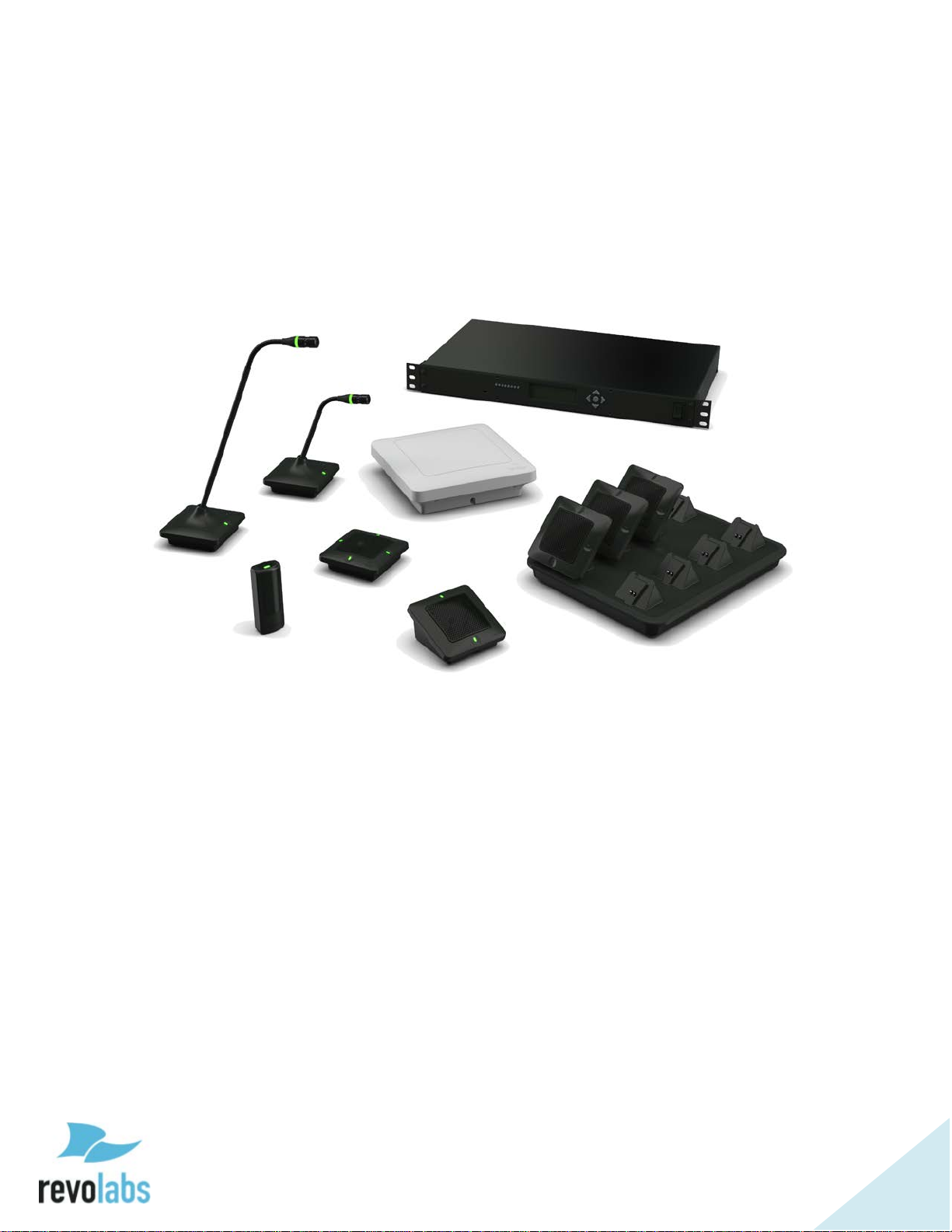
Components
Depending on which system you’ve purchased, your Revolabs Executive Elite™
System package contains the following:
• Rack mountable 4 or 8 channel Base DSP Unit
• Remote Antenna receiver unit with mounting plate
• 4 or 8 Microphone Charger Base with external Power Supply
• Power cable, USB cable, network cable
• Euroblock connectors
• Documentation
In addition, you might have bought one or more Revolabs Elite wireless
microphones. Each microphone package will include:
• Revolabs Elite wireless microphone (different styles)
• Lanyard and over-the-ear speaker element (wearable microphone only)
• Batteries
• Documentation
The Executive Elite Base DSP unit contains all the logic required to support the
audio signal from the microphones in the different output formats (analog
audio, digital audio over AVB). It supports the management interfaces (front
panel, local web UI, room control system UI), as well as communication with
the remote cloud based UI.
The Remote Antenna receiver contains all components required to receive (and
send) audio signals from (and to) the microphones. It includes the required
diversity antennas. The remote antenna also controls over the air
synchronization between systems, and provides the scan of the RF frequency to
determine how many (additional) microphones might be used in the area. The
remote antenna receiver communicates with the Elite Base DSP unit using a
direct IP connection (Cat 5e or Cat 6 cable).
The Charger Base stores and charges the wireless Elite microphones when not
in use. Communication capabilities are not required for the charger tray
because all information transferred between microphones and the Elite base
DSP unit passes over the wireless connection. This includes pairing of
microphones to receivers, firmware updates of microphones, and commands
sent to the microphones.
Page 15

15
Revolabs Elite wireless microphone systems are designed to work with other
audio equipment typically found in an installation. This equipment is typically
used for:
• Audio Mixing
• Acoustic echo cancellation (AEC)
• Feedback elimination
• Level control
• Equalization
• Noise cancellation
The Revolabs Elite system provides some of these features as well. It is
recommended to use either external or Revolabs audio control systems to
change settings and adapt the audio to your exact needs. Best audio quality is
easier to attain when only one system is used to adapt the audio.
The Revolabs Elite system is designed to optimize audio capture/reproduction
by providing:
• Consistent audio input from all participants
• Minimize room noise
• Mute control
• Wireless encryption
• Automatic channel selection
• Full duplex audio.
Page 16

16
Revolabs wireless microphones and transceivers, receive signals (audio,
commands) from the remote antenna receiver, while sending audio back to the
antenna and the Base DSP unit. There are several different microphone and
microphone adapter types available with the Executive Elite:
• Omni directional tabletop microphone
• Directional (Cardioid) tabletop microphone
• 12in Gooseneck tabletop microphone
• 6in Gooseneck tabletop microphone
• Wearable Presenter microphone and transceiver
• TA4 microphone adapter (mini-XLR) and transceiver
• XLR microphone adapter and transceiver
To transmit audio, Microphones need to be paired to their receiver and antenna
as described later in this document.
Finally, you might have purchased additional components like the ceiling
mount kit for the remote antenna receiver, or the cross-over adapter to install
wireless tabletop microphones permanently or semi-permanently on your
tables.
Page 17
17
Installation
2 1 3
4
5 6 7 8 9
10
11
12
13
14
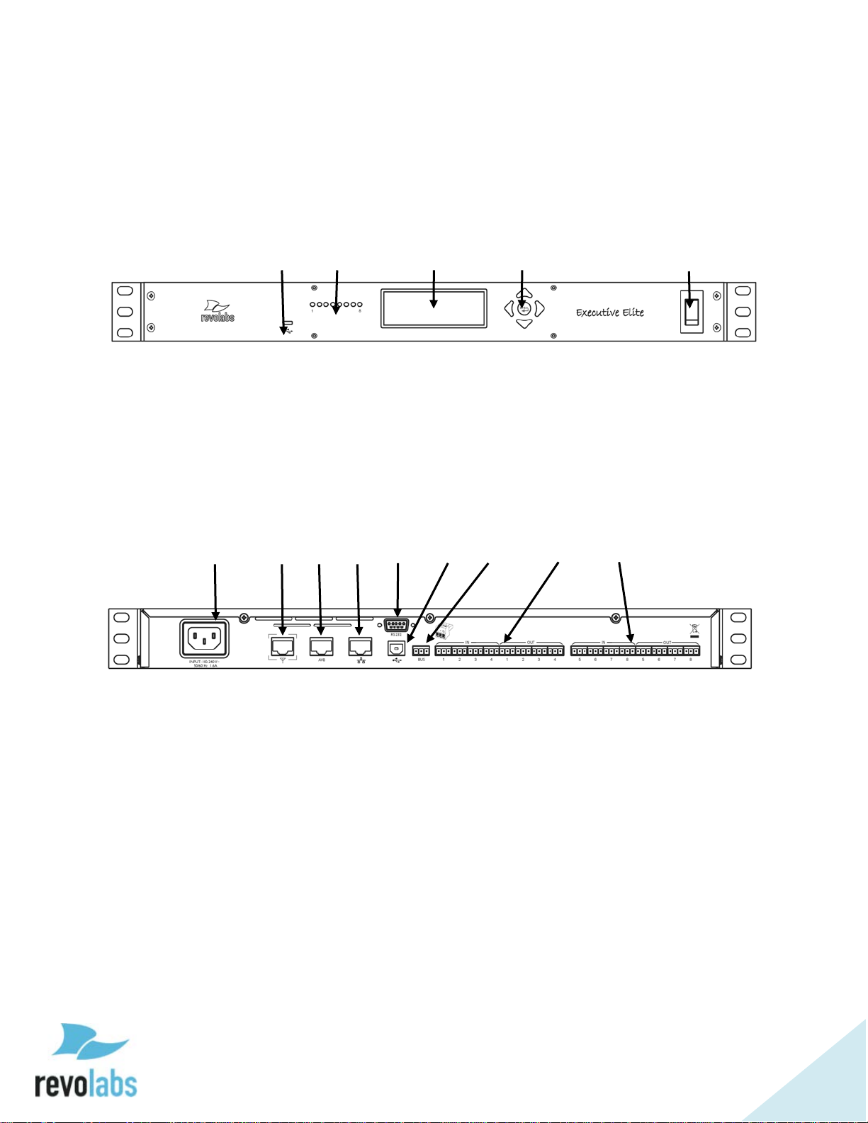
Base DSP Unit
The Revolabs Executive Elite Base DSP Unit, shown below in front and rear
panel views, provides the audio output of the wireless microphones and the
management interfaces to administer the microphone system.
Front View
1. USB web access to local web user interface
2. Microphone status LEDs, showing pairing and mute status (8 LEDs on
the Executive Elite 8 microphone system, 4 LEDs on the executive
Elite 4 microphone system)
3. Front panel LCD displaying system information
4. Navigation buttons controlling content of front panel LCD display
5. On/Off switch
Rear View
6. Power In Receptacle (100-240 VAC, 50/60 Hz)
7. Remote Antenna Connector, PoE enabled
8. AVB network connector
9. LAN network connector
10. Serial port for room control interface
11. USB connector, future use
12. Euroblock connector (grey), Executive HD compatible synchronization
bus
13. Euroblock Connectors, analog audio in (black) and audio out (green),
microphone channels 1-4
14. Euroblock Connectors, analog audio in (black) and audio out (green),
microphone channels 5-8 (only on Executive Elite 8 microphone
systems)
Page 18
18
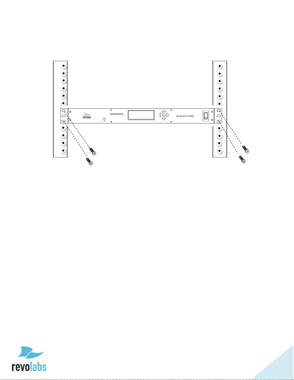
The Revolabs Executive Elite Base DSP Unit is designed to be installed into a
standard 19” AV rack using the attached rack ears. Screws are not provided.
Page 19
19
Remote Antenna Receiver
Routing channels
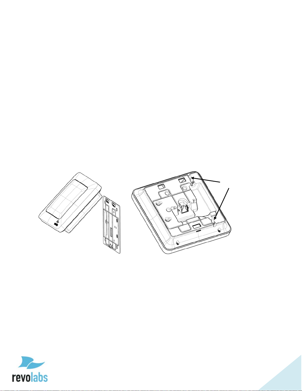
The Remote Antenna Receiver consists of two pieces – the mounting plate and
the Antenna housing. The Remote Antenna Receiver is installed similar to a
wireless access point. Best locations are high on the wall, facing into the room
in which the microphones are located. Each Remote Antenna Receiver
supports one Base DSP Unit. If more than one Base DSP Unit is installed for a
room, e.g. more than eight microphones are required, several Remote Antenna
Receivers will be installed in this room. It is best to install the receivers on the
same wall facing into the room, spaced at least 12 inches (30 cm).
The Remote Antenna Receiver contains several antennas to provide the best
transmission and reception of the radio signal to and from the microphones.
Page 20
20
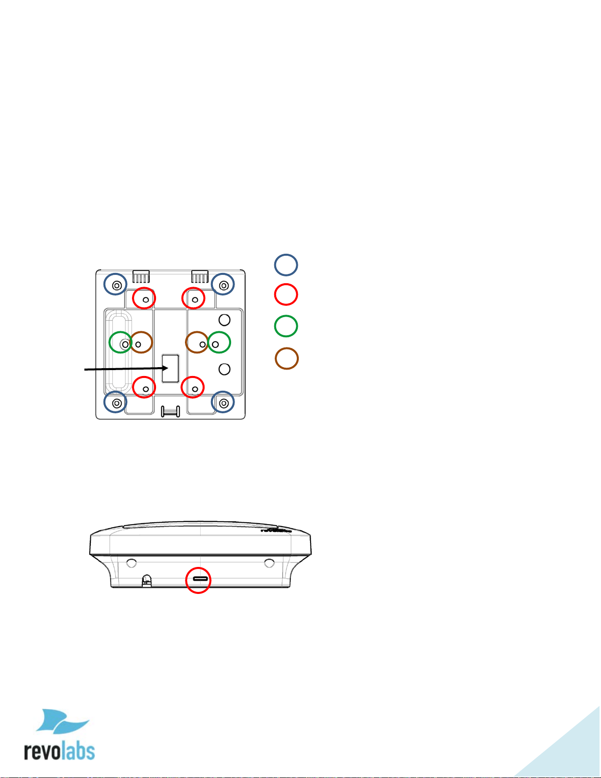
The back-plate of the Remote Antenna Receiver provides means to install the
TOP
Four corner holes – wall installation
Four central holes – US single gang
Two outside horizontal holes –
Two inside horizontal holes –
Under-ceiling installation
Network
antenna in different environments. See the below diagram on how to install in
the different environments.
Independent on which way the wall plate is attached, do not over-tight the
screws.
When installed on the wall or on an electrical one gang or two gang box the
network cable can be routed through the Network cable opening. Alternatively,
the network cable can be routed to leave the Remote Antenna Receiver either
on the top or the bottom, using the provided routing channels.
cable
opening
or dual gang
European single gang
Once the back plate is attached to the wall and the network wire is connected
to the Remote Antenna Receiver and routed correctly, the Remote Antenna
enclosure is attached to the back plate by slipping it from the top onto the two
hooks, and then pressing the bottom back against the wall plate until the snap
clicks in.
To separate the Remote Antenna Receiver housing from the wall plate insert a
screwdriver from the bottom into the slit and press against the snap while
carefully pulling the Antenna Receiver forward until the Antenna Receiver
releases from the snap. The Remote Antenna Receiver housing can now be
detached from the wall plate.
Page 21
21
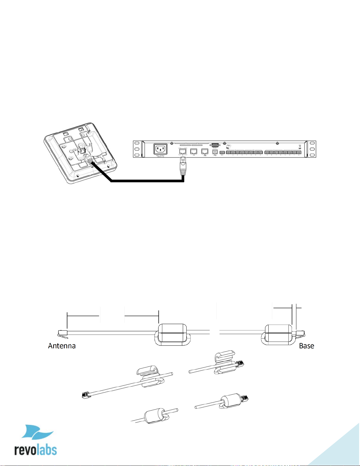
Connect Remote Antenna Receiver to Base DSP Unit
5 in
13 cm
1/4 – 3/8 in
7 – 10 mm
Connect the Remote Antenna Receiver with the Antenna output of the Base
DSP Unit using a CAT 5e or Cat 6 cable.
NOTE: This needs to be a, point to point connection between the two
units. This is a time crucial connection. Routing this connection
through a switch will fail.
The Antenna output of the Base DSP unit provides Power over Ethernet which
is required to power the Remote Antenna.
Before connecting the network cable, ferrite beads need to be installed on
either end of the cable to minimize electro-magnetic interference. One ferrite
bead should be attached ¼-⅜ of an inch (7 – 10 millimeters) from the end of
the cable that will connect to the Base DSP unit. The second ferrite bead needs
to be attached 5 inches (13 centimeters) from the end of the cable that will
attach to the antenna.
NOTE: The Antenna Receiver provides room for the ferrite to be placed in
the antenna casing, underneath the mount plate. If running the
cable through the Network Cable Opening in the mount plate the
ferrite must be installed after the cable has been pulled through.
Otherwise it will not fit through the opening.
Page 22

22
System set-up
Once the Remote Antenna Receiver has been connected to the Base DSP unit,
connect that unit to the power mains and turn the switch on the front of the
unit to “1” from “0”. The unit will now power up. You will see messages on the
front screen providing information until the unit is operational. Once the
Screen with the VU screen is shown, and the Antenna symbol is constant, the
system is operational.
For additional system configuration instructions, see later sections describing
the different user interfaces in this manual.
Revolabs Executive Elite Audio Connections
The Executive Elite Base DSP unit offers three different ways to deliver the
audio from the microphones to post-processing equipment as well as to provide
back channel audio to the microphones.
While all three audio output paths will be active at all times, only one of the
back-channel audio paths can be active. The user interfaces allow selecting
which path should deliver the audio back to the microphones.
Analog Audio
The back panel of the Executive Elite DSP eight channel base unit provides
eight 3.5mm Euroblock inputs and eight 3.5mm Euroblock outputs (the four
channel unit provides four input and four output connectors), providing access
to each channel’s audio signal.
The Euroblock connectors included in the package are designed for easy
wiring. The three terminals (from left to right) correspond to positive +, negative
-, and shielded ground G.
To connect audio In/Out on the Base Station:
1. Use the screws on top of the connector to first open the
terminals.
2. Insert an appropriate 3-conductor cable (2 conductors and
shield) into the terminals.
3. Tighten the screw to secure the cable.
4. Push the connector onto the pins centered under the desired input or
output port on the back of the Base DSP unit until firmly secured.
The microphone output connectors need to be attached to the line-level (0dBu)
input connectors of the post-processing audio equipment (mixer, DSP).
If the analog audio in is used for the back-channel audio, the Base DSP Unit
input connectors (also 0dBu) may then be attached to the output channels of
the post-processing equipment.
Page 23

23
AVB Audio
Beside the analog audio, Executive Elite also supports digital audio input and
output. The AVB connection on the back of the Base DSP unit can be
connected to an AVB enabled network and delivers streams of output audio
data for each microphone, as well as can consume streams of input audio data
for each microphone. For information on how to set up an AVB network and
define AVB talkers and listeners see your AVB network management software.
Synchronizing Executive Elite units
If more than one Revolabs Executive Elite Base DSP unit is used in an area,
the units should be synchronized to ensure best usage of the radio frequency
space, and best system performance. The Executive Elite system provides
three means to synchronize systems, the Sync Bus, the AVB network, and Over
the Air synchronization.
Microphone Density and Radio Frequency Interference
Synchronizing Executive Elite systems is important to maximize the density of
microphones that can be supported in one area. Non-synchronized systems in
the same space block a higher number of radio frequency channels than the
number of microphones they support, causing RF loss and audio drop-outs. It
is therefore important to synchronize all Executive Elite systems that are in
proximity with each other to limit the number of potential audio issues. There
is no disadvantage in synchronizing systems that are not in close proximity.
Synchronization only affects the internal clocks of systems, not the channel
selection they make for their microphones. It is therefore better to error on the
safe side and synchronize even systems not expected to be in direct proximity.
Maximum Density of microphones in one area is affected by the selected audio
quality and whether back-channel audio to the microphones is enabled or not.
It is also dependent on other wireless radio frequency traffic in the vicinity, and
whether that traffic is synchronized or not. Selecting the right RF power
setting is important to limit the area in which RF traffic of a microphone and
receiver is being seen to the coverage area, therefore reducing interference with
adjacent areas. See later user interface sections for information on how to set
these parameters.
Selecting Synchronization Method
Choosing a Synchronization method may be done through either the Web UI, or
the Front Panel LCD.
From the Front Panel the synchronization mode may be selected from the
System Clock submenu, under System Settings. Once the mode is selected,
the interface will automatically prompt the user with a choice of Internal or
External clock mode. Only one Internal can be set for any sync mode; this
Page 24
24
device will be the clock source to all synchronized systems. All other devices
need to be set as External, and use the clock signal of the Internal.
Through the Web UI, synchronization mode can be set on the System
Configuration page. In the table on the bottom left of that page are two
dropdown menus. The first is for the synchronization mode, and the second
for setting the system as Internal (Primary on the Executive HD) or External
(Secondary Mode on HD) clock mode.
Synchronization Bus
The synchronization bus allows connecting several Executive Elite Base DSP
units together to manage the clock between the systems.
The Synchronization bus also allows synchronizing Executive Elite Base DSP
units with Executive HD™ receivers in the same vicinity. While the
synchronization bus in Executive HD installations also managed group mute
control, this capability is handled differently in Executive Elite. When installed
together with Executive HD systems the bus will therefore only provide
synchronization data, not mute data between Executive Elite and Executive HD
systems. However, mute groups managed between Executive HD systems can
still be managed using the bus.
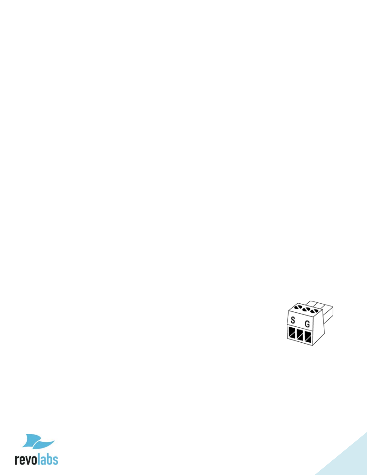
The synchronization bus cable is connected to the grey Euroblock BUS
connector on the Executive Elite Base DSP unit using a standard 3.5mm
Euroblock connector. The wire used should be 26AWG or better, shielded
cable. The distance between the furthest External and the Internal must not
exceed 300’ (90 meters).
The terminals of the BUS connector should be wired in parallel via either a
daisy chain connection or terminal block split. The three contacts of the
Euroblock connectors are as follows from left to right.
S. Sync
¯¯. Not used in Executive Elite (Master Mute in Executive HD)
G. Ground
If the synchronization bus is used to synchronize Executive Elite
systems with Executive HD systems, one of the Executive HD systems needs to
be set as the Internal, making that system the clock master. All Executive Elite
Base DSP units will have to be set to use the external clock.
AVB Synchronization
If all Executive Elite Base DSP units are connected to the same AVB network,
the AVB network can be used to synchronize the systems with each other.
This simplifies installation of Executive Elite systems as no additional
Page 25

25
synchronization bus is required. However, it does not allow synchronization in
a mixed environment with both Executive HD and Executive Elite systems as
Executive HD Systems do not support AVB.
The Setup for ABV sync is through an AVB capable switch. Once the Executive
Elite synchronization mode is set in the Web UI or Front Panel to AVB, select
Auto as the Clock Mode. Through the AVB networking software set up a
network of elite systems, where at least one system is a “Talker” and the other
systems are “Listeners” to that system. The architecture also allows for
communication chains, where one Elite is set up as a Listener to a system in
the chain, and as Talker to systems further down in the chain.
OTA Synchronization1
Executive Elite systems have the ability to synchronize with other Executive
Elite systems in radio frequency range using over the air (OTA)
synchronization. This synchronization method does not require any wiring
between Executive Elite Base DSP units. In OTA mode, systems exchange
synchronization information using radio signals, therefore allowing systems in
vicinity to auto synchronize. To enable OTA synchronization, select OTA as the
Clock Source.
1
OTA Synchronization will be available starting with Executive Elite Software version 1.2
Page 26

26
Front panel user interface
The Front panel user interface is one of four interfaces available to manage an
Executive Elite system. The others are the local web UI, the Cloud Server Web
UI, and the CLI (room control) interface and are described later in this
document.
The front panel contains four areas:
1. On/off switch
2. 4 / 8 LEDs (depending on the version of the Executive Elite base DSP
unit)
3. Graphics LCD display
4. 5 button navigation keypad.
The on / off switch powers the Executive Elite base and the connected remote
antenna receiver on and off. During operation, this switch should be in the
“1”, or ‘on’, position.
The LEDs on the front panel show the current microphone states. An LED that
is off indicates that there is either no microphone paired to this channel, or the
paired microphone is in the charger, out of reach, or switched off. A green
blinking LED indicates an active microphone that is unmuted. A red blinking
LED, showing a double blink, indicates an active microphone that is muted. A
rapidly red blinking LED with a single blink indicates the microphone is
upgrading. A constant red LED indicates a channel on which microphone
pairing is taking place at the moment.
The LCD screen together with the navigation keypad allows easy monitoring of
the Executive Elite system as well as managing some system settings without
additional equipment. Its home screens provide information on audio levels,
radio signal strength, and access to gain settings for the analog audio output.
The menu structure displays system information, and allows changes to some
system and audio settings. The front panel can also be used to pair and unpair microphones. It does not replace the local web UI interface or the cloud
based management interface to manage all options and functionality of an
Executive Elite system. The front panel interface will also not allow access to
password protected areas of the interface unless the system has first been set
up using the local web UI.
Page 27

27
Home Screens
When starting an Executive Elite system, the first page that comes up on the
Front Panel LCD is the Volume Unit (VU) screen. This screen is one of the 3
home screens on the Front Panel UI. Using the “up” and “down” keys to the
right of the LCD while on the VU page will show the other two home screens.
The VU screen shows the audio volume for each unmuted, linked microphone,
as well as battery charge information.
“Up” from the VU screen, the RF View home screen shows the radio signal
strength as measured on the receiver for each microphone.
“Down” from the VU screen, the Gain control screen shows the VU meters as
well as the input gain setting for each microphone channel, which the user can
change from this screen. To adjust the gain, a user presses the “Enter” while
on the gain screen, and a black highlighted selection will appear. The channel
is selected using the “left” and “right” keys and once in the correct channel, the
up and down keys change the gain in 1 dB steps. The gain setting for the
highlighted channel is listed on the right-hand side of the LCD. The user
cannot leave the gain control screen while in channel selection mode. To leave
the screen, press “Enter” again to get into the normal mode. “Up” and “Down”
will now switch between home screens again, and using the “Right” arrow key
will enter the main menu.
Page 28

28
When changing the gain or entering any menu in the front control panel that
allows the user to changing values, a password prompt will appear before the
user is allowed to proceed. To enter the password, use the right and left arrow
keys to select a digit, and the up button to change the number of that digit (0-
9). Hitting Enter will submit the password, and down brings the cursor to the
cancel button. On the front panel, the password will be valid for 20 minutes,
unless the user explicitly logs out in the Admin Settings submenu as described
further below. The factory preset password is 7386, and can be changed either
through the Admin Settings menu on the front panel interface, or the System
Configuration menu on the local Web UI.
Page 29
29
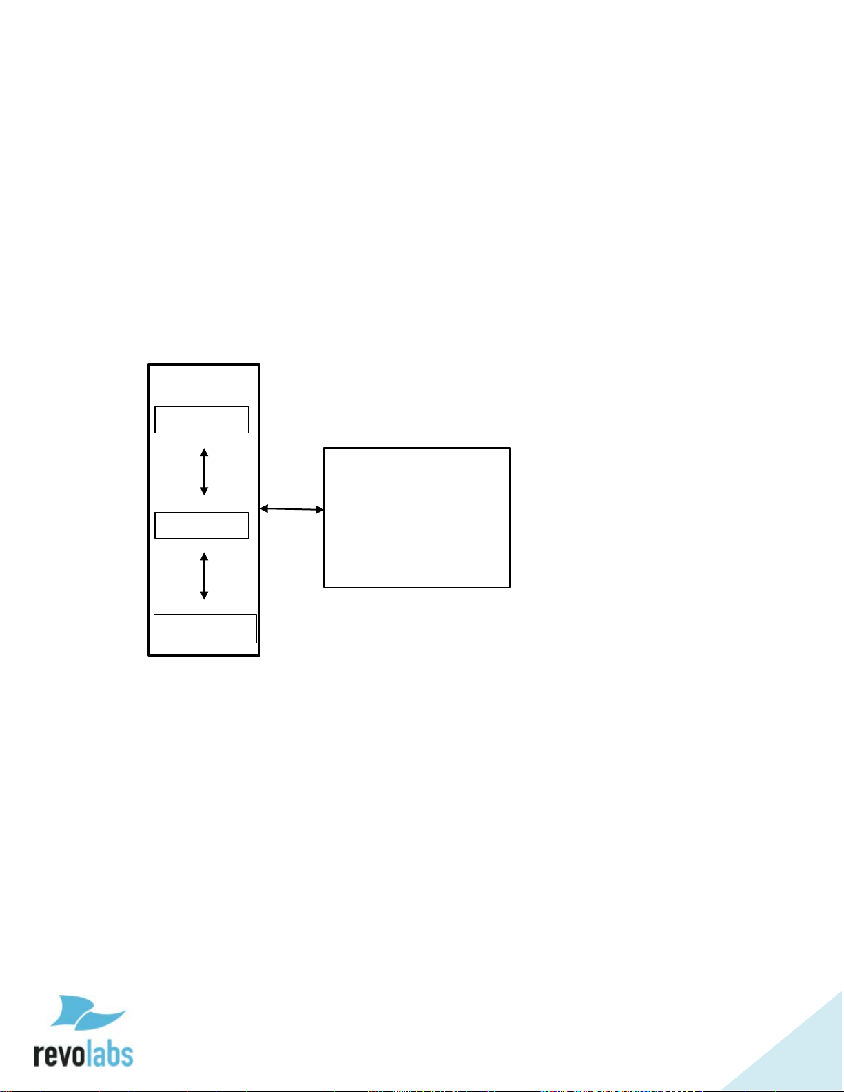
All three home screens are split into 3 sections, and each section shows a
different type of information. On the far right-hand side of the screen, the
Home screen name is displayed at the top of the external systems information
box. Underneath it there can be up to 4 icons, showing if certain external
systems are connected.
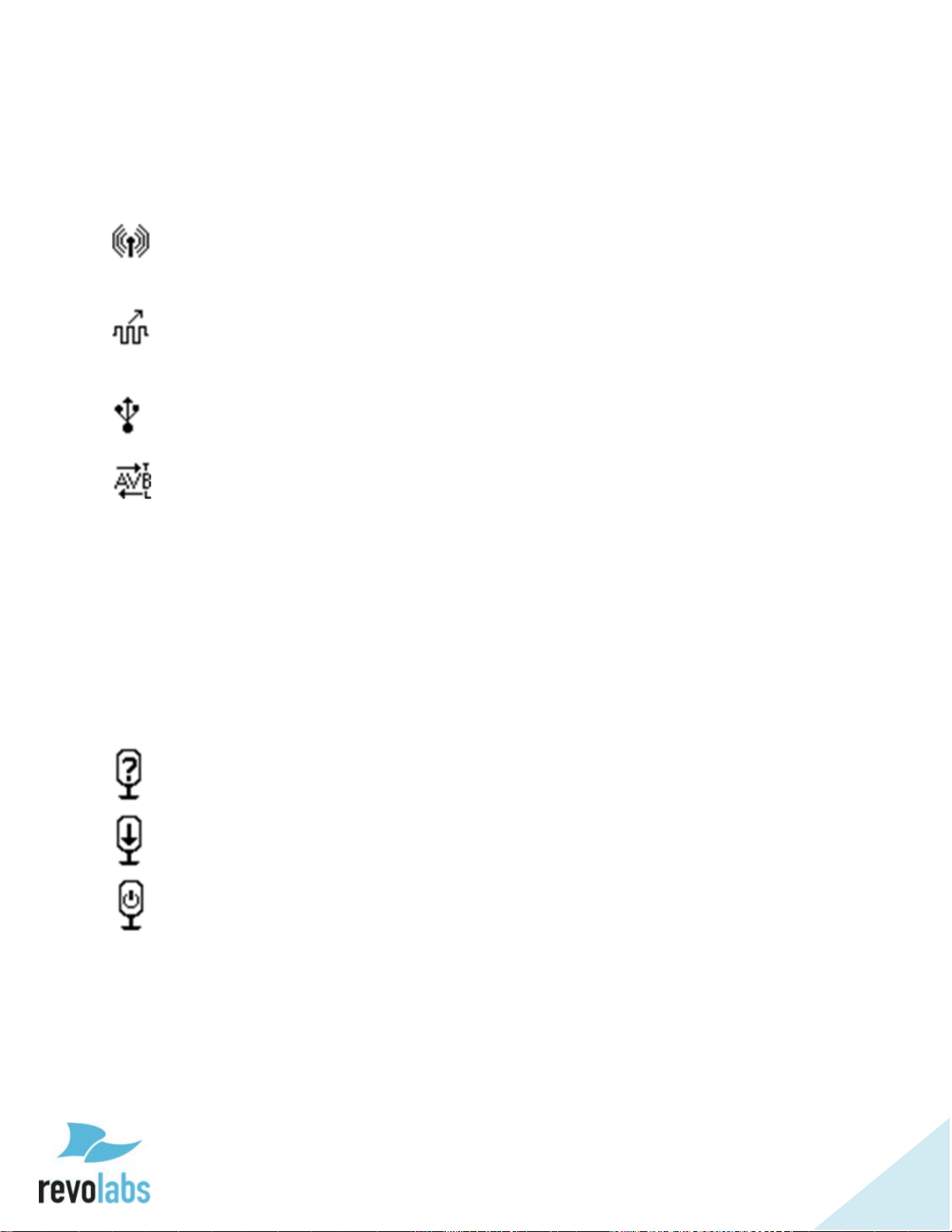
- Antenna. The only icon guaranteed to be in this box. If it is blinking, an
antenna is not communicating with the Base DSP unit. If it is solid,
communication is passing between the Antenna and Base.
- Wired Sync. If a wired sync buss is being used to sync clocks between
Executive systems, the synced Elites will show this icon. Remember that sync
mode must be set before the base will look for an external clock.
- USB. When the front panel USB is in use, this icon will show
communication is being received through that port.
- AVB. When AVB is plugged into the Base, the “AVB” icon will appear.
Until the Base is set up as a “talker” or “listener”, the arrows above or below
“AVB” will not appear. To check if the Base is set up for either, remember “T”
is for talker and “L” is for listener.
Separated from the external systems box by a vertical line is the channel
information section of the Front Panel UI. At the top, each channel is labeled,
and two rows underneath provide different information depending on which
home screen is currently selected.
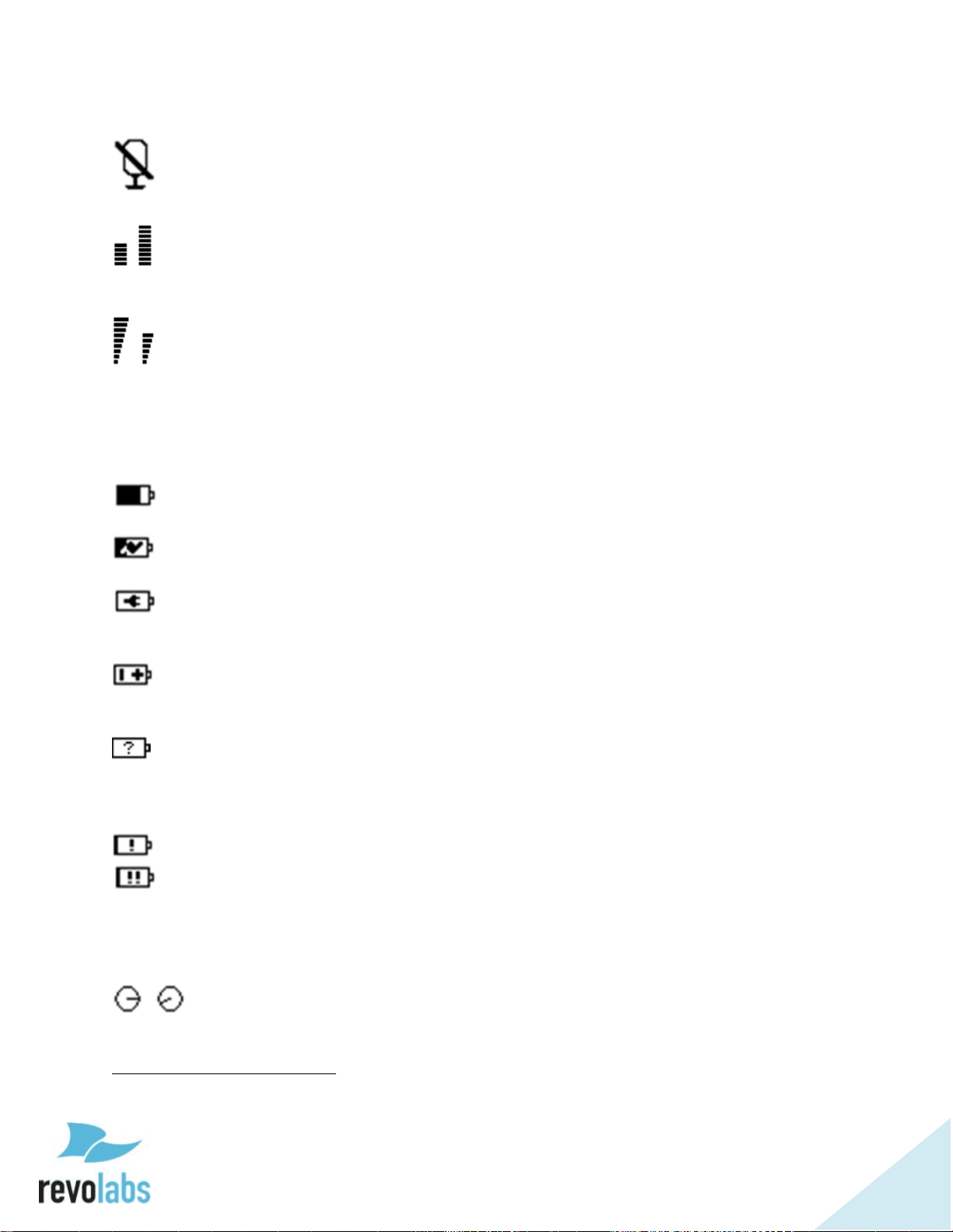
On all screens, the top row will show microphone status beyond linked with the
following icons:
- Microphone Lost Link, or Unknown Status Microphone
- Firmware Update in Process
- Stand-by Mode
Microphone channels that have no microphone paired, a charging microphone,
or when the microphone is switched off, will show no information.
Page 30
30
Additional information from this row can be found in the following forms:
- Mute Symbol. Will show on the VU screen for a linked, muted
microphone.
- VU or Gain Meters. VU screen shows a VU meter for a linked, unmuted
microphone, while the Gain screen meters look the same, but do not change
unless set, and appear for all linked microphones.
- RF Meters. The RF screen will display the strength of the transmission
from any linked microphone as it is received by the base. Microphones
experiencing interference or far away will have a lower RF.
The second row displays battery information when seen on the VU and RF
screens, using the following icons:
- For a linked microphone, the battery level icon will show the charge level
by the amount of black in the battery.
- While in the charger, the battery symbol also shows a charging symbol
overlaid over the battery-charge icon2.
- A microphone using a permanent cross-over adapter will be shown with
a power connector battery symbol. A permanent cross-over adapter is one
where the microphone does not use batteries.
- A battery symbol with a +/- indicates a non-rechargeable battery or
wrong battery type. Such a battery will not charge when placed in the charger
tray.
- The type of a battery is only determined when the microphone is placed
in a charger after inserting a new battery. Up until this time the battery
symbol will show a battery with a question mark in it, indicating that the
battery type is unknown.
- Low battery, under 10% remaining.
- Very low battery, under 5% remaining.
On the gain screen, this row will not show battery information, instead having
a row of digital gain “knobs” that will match the gain shown in the meters
above them.
- Gain knob
2
It might take a few minutes for the charge symbol to appear after a microphone was placed in
the charger.
Page 31
31
Front Panel Menu Tree
RF Screen
VU Screen
Gain Screen
Main Menu
6. Reboot
Home screens
The menu tree is navigated by using the “Right” button to enter a menu, the
“Left” button to leave a menu, and the “Up” and “Down” buttons to scroll
between the options in the menu. With the “Enter” button a menu entry is
selected – if it is a sub menu, the submenu will open, if it is a check box this
will either check or un-check the option, and if it is a selection (“radio button”)
it will select that value. If it is a value entry, it enables the “Up” and “Down”
buttons to change the value. Pressing enter again in that case will store the
value and leave the data entry mode.
Main Menu
1. System Info
2. System Settings
3. Audio Settings
4. Microphone
Management
5. Screen Contrast
In the main menu the first five options are sub menus that are described
below. The fifth entry “Screen Contrast” controls the contrast of the front panel
when selected, and the sixth entry “Reboot” reboots the system.
Page 32

32
System Information
System Info
Base Information
Antenna Information
Microphone Information
8. Mic 8 Information
Mic 1 Information
Network Information
Network Information (LAN)
Network Information
Network Information (AVB)
4. Master MAC
The first option in the Main Menu is System Information. System Information
offers information on the Base DSP unit, the Remote Antenna Receiver, the
Microphones, and the available network connections. None of the information
in this menu and the submenus can be changed.
1. FW Version
2. Product Version
3. System Name
4. Product Name
1. Base
Information
2. Antenna
Information
3. Microphone
Information
4. Network
Information
1. Link Status
2. MAC Address
3. FW Version
1. Mic 1 Information
:
1. Network Information
(LAN)
2. Network Information
(USB)
3. Network Information
(AVB)
1. Mic 1 Type
2. Mic 1 Version
3. Mic 1 ID
1. IP Address
2. MAC Address
3. Subnet
4. DHCP enabled /
disabled
5. Gateway
6. DNS Server 1
7. DNS Server 2
(USB)
1. IP Address
2. MAC Address
1. MAC Address
2. Link Status
3. PTP Mode
Base Information provides information on the current firmware running on the
base DSP unit, the product version, product name, and system name.
The Antenna Version menu indicates whether the link to the antenna is up or
down, shows the Mac address of the remote antenna, and lists the Firmware
version of the software running on the Remote antenna.
In the Microphone Information submenu paired microphones are listed.
Selecting any of these microphones will present the information on that specific
Page 33

33
microphone, including microphone type, firmware version, and the ID of the
System Settings
5. Admin settings
Region
18. Venezuela
RF Power
Admin settings
System Synchronization
microphone.
In the Network Information section the three different networks available to the
user are each given a submenu. Network Information (LAN) provides
information about the standard LAN connection, including whether DHCP is
enabled or disabled, the IP address of the base DSP unit in the LAN network,
the MAC address of the interface, as well as other network information. The
Network Information (USB) option provides network information for the USB
connector on the front of the Elite base DSP. Finally, Network Information
(AVB) provides information on the AVB connection in the back of the Elite base
DSP unit. This includes the link status, the MAC address of the interface, the
PTP mode, and the MAC address of the AVB master.
System Settings
The System Settings submenu allows the user to control some of the Executive
Elite’s system settings.
The Remote Management checkbox at the top of the menu enables and
disables the room control (CLI) interface on the base DSP unit.
The Region menu allows selecting the region in which the Executive Elite
system is used.
NOTE: You need to select the region or country you are using the system
1. Remote Management
On/Off
2. Region
3. RF Power
4. System Clock
1. USA/Canada
:
1. Auto Scaling on/off
2. 0 – 20 ft (0 – 6 m)
:
6. 150 – 300 ft (46 – 90 m)
1. Local
2. Sync Bus
3. AVB
4. System Clock Mode
1. Set Password
2. Log Out
in. As part of this selection the frequency band in which the
Page 34

34
Executive Elite system operates is selected. Selecting a country or
region different from the one you are in might revoke the right to
use the system. If you are unclear which region or country you
should select, please contact Revolabs support.
The RF Power settings allow adjusting the RF signal strength of the receiver,
limiting RF traffic and interference with other areas. It is recommended to
select an RF setting that provides good RF coverage with minimal local area
interference. An RF Power setting that provides a signal strong enough for a
microphone to be 150 – 300 feet away from the remote antenna receiver might
also be seen by other Revolabs devices in the vicinity. We recommend testing
with different RF settings and using the RF Spectrum Analyzer in the local web
UI to gauge the effect of the different settings. Auto Scaling should be disabled,
except in high RF environments as it allows the system to automatically reduce
RF power when it is not required.
The System Clock menu allows setting the synchronization mode of the
Executive Elite system. After selecting a mode, the system will open the
System Clock Mode submenu, prompting the user to choose if the system will
be Internal, and share its clock, or External, and search for an external clock
master. After selecting Internal or External, the base will reboot to apply the
changes.
In the Admin Settings menu the standard password used on the local web UI
and the front panel can be changed. The user can also log-out of the front
panel from here.
Page 35

35
Audio Settings
Audio Settings
3. Low Pass Filter
System Audio
4. Back Channel on/off
High Pass Filter
8. Microphone 8
Mic 1 High Pass Filter
5. 220 Hz
Low Pass Filter
8. Microphone 8
Mic 1 Low Pass Filter
4. 12000 Hz
1. System Audio
2. High Pass Filter
The Audio Settings section allows changing audio properties of the Executive
Elite system.
The System Audio submenu controls the partitioning of the available RF space,
controlling the number of bytes allocated to transport the audio data between
microphone and the base DSP unit.
Standard Definition (SD) reserves less RF space per microphone channel,
reducing the audio quality slightly as a higher compression has to be used, but
allows more microphones to be used at the same time. High Definition (HD)
allocates more RF space per microphone channel, increasing the audio quality,
but decreasing the number of microphones that can be used at the same time
in one area. The local Web UI provides additional information on the
recommended maximum number of microphones per area based on each
setting.
If the Executive Elite system is used together or in proximity with legacy
Revolabs systems (Executive HD), the Legacy Mode selection should be used for
best integration. Compared to the HD audio implementation in Executive Elite,
Legacy Mode requires more RF space per microphone. It should be turned off
in environments where no Executive HD systems are present.
The back channel audio checkbox enables or disables return audio from the
base to the Executive Elite microphones. If back channel audio is not used,
this option may be switched off to open additional RF space. If the Executive
Elite system is used in Legacy HD mode, the checkbox cannot be unselected,
as legacy systems require the audio back channel.
1. Standard Definition (SD)
2. High Definition (HD)
3. Legacy Mode on/off
1. Microphone 1
:
:
1. Microphone 1
1. None
2. 110 Hz
3. 140 Hz
4. 175 Hz
1. None
2. 4000 Hz
3. 8000 Hz
Page 36

36
NOTE: The System audio page in the local web UI provides information on
Microphone Management
9. Microphone 8: linked
Options:
Linked: Turn off or un-pair
Pair All Wizard
pairing of all microphones
the recommended maximum number of microphones for each
selected setting. The RF analyzer page in the local web UI shows
the exact use of the RF space, and provides information on
additional microphones that can be added based on average and
peak activity in the RF environment.
The High-Pass and Low-Pass filter menus manage audio filters for each
microphone. High-Pass filters should be used in rooms that have high level of
background noise from air conditioners, projectors, etc. Low-Pass filters
should be used in applications and installations that do not support wide band
audio to ensure that no unwanted side effects occur.
Microphone Management
:
Pairing and un-pairing of microphones is managed by the Microphone
Management menu.
The “Pair All Microphones Wizard” guides the user through pairing of
microphones to all channels and should be used when installing a new system
or when all microphones on an existing system are being exchanged. The
wizard allows channels to be skipped during the process, and may therefore be
used to pair less than a full set of microphones to a system as well.
Selecting an individual microphone will open options based on the current
status of the microphone on that channel. Any channel with a microphone
paired to it can unpair that microphone. A microphone can also be re-paired,
deleting the current pairing information on the base DSP unit, and starting the
pairing process. The last option in this menu only appears when a paired
microphone is active (linked). A linked microphone may be shut down
remotely by selecting “Turn off”.
If no microphone was paired to the selected channel, the menu will only offer
the pairing option.
1. Pair All Wizard
2. Microphone 1: unpaired
3. Microphone 2: paired
4. Microphone 3: link lost
5. Microphone 4: charging
6. Microphone 5: charged
Wizard guiding user through
Unpaired: Pair microphone
Link lost: Re-pair or un-pair
Charging: Re-pair or un-pair
Charged: Re-pair or un-pair
Paired: Re-pair or un-pair
Page 37

37
Local Web UI
The local Web UI allows managing an Executive Elite base DSP unit through a
web browser. The local web UI can be accessed either through the IP network
if the Executive Elite base DSP unit is connected to the LAN using an Ethernet
cable, or through the USB connector in the front of the base DSP unit.
Running the local web UI requires Java to be installed on the computer that is
opening the browser page.
NOTE: Supported web browsers are Microsoft Internet Explorer, Google
Chrome, and Mozilla Firefox.
Connecting to the local web UI
When connecting a Computer for the first time using the USB interface, the PC
may need to install driver software to enable web access through the USB port.
This installation could take several minutes. During this time an installation
message like this might be shown on the Computer:
NOTE: If you do not see this or a similar message, the driver may not have
been successfully installed. If this occurs, connection to the web
interface of the Executive Elite System cannot be established
through the USB port. This is likely due to your computer’s driver
update configuration. If the problem continues, please check if
your computer has ‘auto update’ disabled and/or contact your
administrator.
Once the driver is installed, the front panel LCD will show an overlay with the
IP address for the USB interface. The IP address of the USB interface can also
be found by visiting Main Menu – System Information – Network Information –
Network Information (USB).
If the Executive Elite Base DSP unit is connected to the LAN, you can also use
a computer on the same subnet with no firewall in between to access the web
UI interface. The Elite system is factory pre-configured for DHCP and will
request an IP address from your DHCP server. The IP address of the LAN
interface can be determined through the front panel interface by visiting Main
Page 38

38
Menu – System Information – Network Information – Network Information
(LAN).
Logon page
Open a supported web browser on your Computer or laptop and type in the IP
address of the Executive Elite Base DSP unit. Once the web browser connects
to the Executive Elite base DSP unit, it will show the logon page, asking for the
system password. The password for the local web UI and the front panel is
shared, and the factory default is 7386. If this password is changed, either
through the front panel or the web UI, both interfaces will require the new
changed password.
After entering the password and clicking on the Login button, the web interface
will progress to the next page.
The checkbox on the bottom of the password entry form will prevent the Web
UI from timing out during a period of inactivity. The Web UI will still log out 60
seconds after the browser window is closed. When selecting this option
remember to log off through the web interface, or close your web browser
before leaving the computer.
Page 39

39
First time usage
When installing the Executive Elite Base DSP unit and opening the web
interface for the first time, the system will require some system wide settings
that need to be made before the system becomes operational. Webpages to
make these selections will be opened first.
The New Systems Configuration page asks for system information. The system
name will help identifying the system in multi-system installations. It is
mandatory to provide a name. Country/Region is required to define wireless
settings in the system. You need to select the country or region in which the
system is being used.
NOTE: Selecting a different region than the region you are using the
system in may void your right to use the system! If you are unsure
about which region to select, please contact Revolabs support at
support@revolabs.com.
Cluster Name allows for common microphone group definitions across several
Elite Systems. Elite Systems that are in the same Cluster will find each other
in the network, and coordinate mute commands. This allows definition of
microphone groups across several Base DSP units, enabling mute behavior
across larger groups of microphones. In standalone systems that are not
supposed to coordinate behavior with other systems, do not provide a Cluster
Name. If you are not sure whether this system will be part of a Cluster, or you
currently do not know the cluster name, do not provide a name at this time.
Page 40

40
You can enter a Cluster Name later through the System Configurations page of
the web user interface.
Click Next once you have provided the information on this page.
The New System Configuration page allows registering the Executive Elite with
an existing revoCloud account. If a registered user email and password are
provided, the Elite Base DSP unit establishes communication with the Cloud
Server and adds its information to the system registry on the server.
The Create New Account button will bring up a registration window to create a
new account on the Cloud Server. Further details on this process are provided
in the revoCloud section of this document.
If the Elite System will not be registered with the Cloud Server at this time,
Remind Me Later will close the window, and remind the user to register after
the next login. “Do not Register” will skip the registration, and will not remind
the user to register the system later. The Elite System can always be registered
at a later time through the local management interface.
After leaving the System Registration page, a popup will appear, asking if
microphones should be paired now or later.
If the microphones are ready to begin pairing, a short pairing wizard will walk
the installer through the process of pairing them to the available channels. If
Page 41
41
microphones are not ready to be paired at this time, they can be paired from
the Web interface later on.
Once pairing is finished, or if “later” was selected on the pairing page, the Local
Web UI will redirect to the Monitor page. This page will also be the first page to
come up after logging in on all future visits to the Web UI.
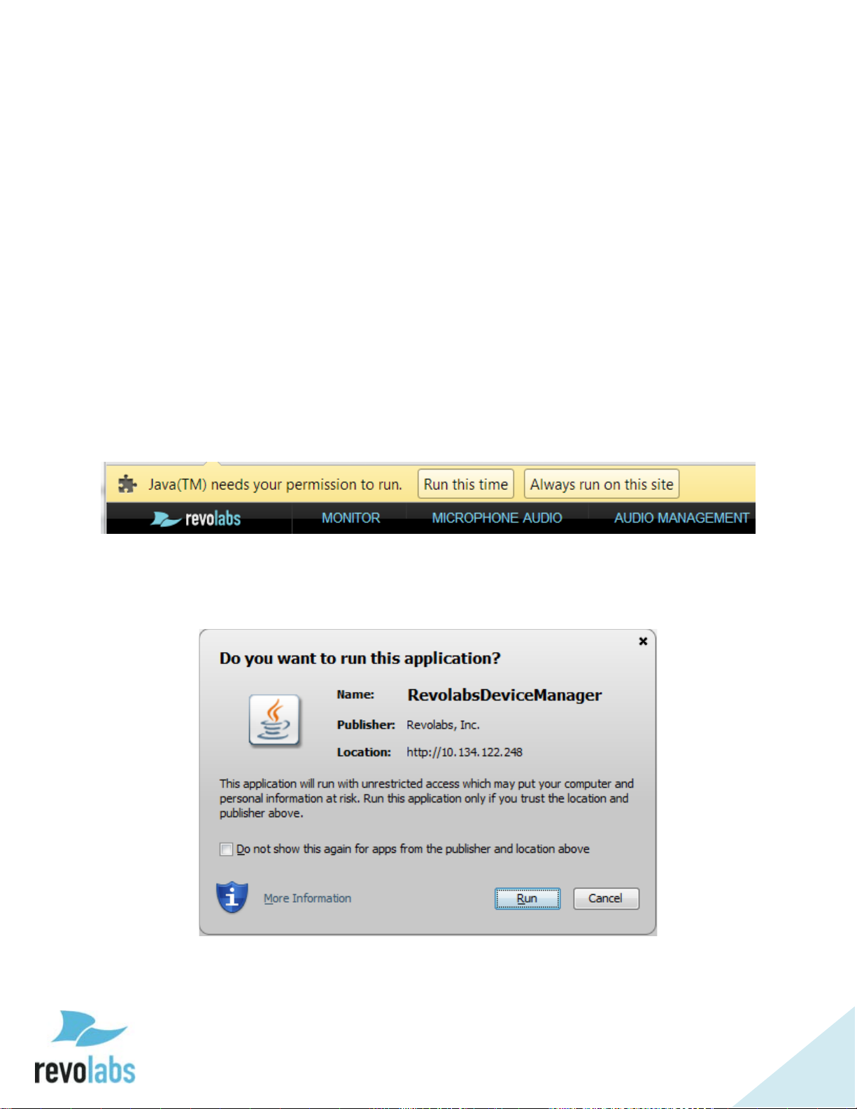
Monitor Page
The local Web UI requires Java applets to provide real-time information on the
system status and manage the system. Therefore when entering the page the
first time and depending on the web browser that is being used, two warnings
might be displayed. The first one asks to run Java, and depending on your
preferences, you might allow Java to run on this page this time, or always.
NOTE: If Java is not enable on your computer, or you do not allow the
Java applet to run, the local web UI cannot provide all of the
system information, changes to settings might not be
communicated to the Executive Elite base DSP, and the user might
be barred from some features of the web UI.
The web browser might also ask permission to run the Java application.
Again, depending on the preference, you may allow Java to run just this time,
or always. If you check the box on the screen, a trusted security certificate is
added to the Java security settings.
The Monitor page provides current status information for the microphones in
your current system. The page lists the microphone channels, either in
Page 42
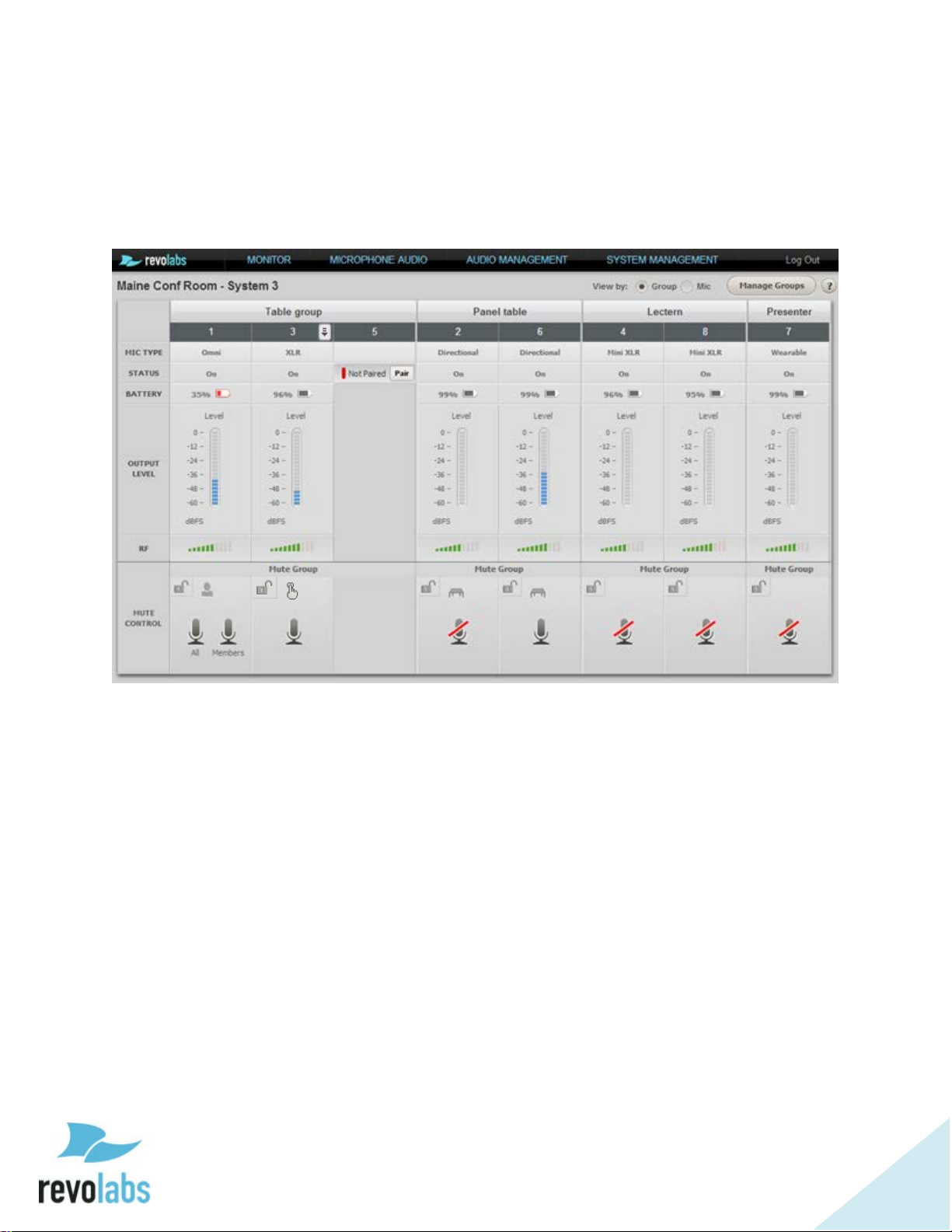
42
numerical order or sorted by groups, and information on each channel. If no
1
2 3 4 6 5
7
microphone is paired on a channel, a pairing button is provided to pair a
microphone.
The top line provides the group name. Factory preset, all microphone channels
are assigned to a group called “Default”.
1 – Mute Lock Button – Enable or Disable mute from the microphone.
2 – Chairman Symbol – This Microphone is set as Chairman for its group.
3 – Individual Mute Button – Works like the microphone’s mute would, but
through the Web UI.
4 – Tabletop Mute Symbol – Indicates Tebletop mode.
5 – Push-to-Talk Mute Symbol – Indicates Push-to-Talk mode.
6 – Chairman Mutes (All and Members) – Mute all microphones in the group or
mute every microphone besides the chairman.
7 – Microphone Dropdown Menu – Appears when mouse is hovered over the
column. Click for Microphone menu.
For a paired microphone, the Monitor page provides the type of microphone,
the current status, the battery charge percentage, the current audio output
level, and the strength of the radio signal of the microphone as detected by the
remote antenna. The Mute Control area provides information on mute group
settings and the current mute setting per microphone or per group. This area
allows changing microphone settings, from locking a microphone mute button
Page 43

43
to muting and unmuting microphones based on the group settings. The
microphone symbols reflect the current mute status for each microphone.
If it is preferable to view microphones in numerical order, rather than by group,
the “View By:” option at the top right of the page will change the view mode.
Beside this option, the Manage Groups button will navigate to the Group
Management page, also found under the Audio Management menu.
Both the Monitor and Microphone Audio pages have a microphone control
dropdown menu accessible from the microphone tables. To open the menu,
hover over the desired microphone’s column and a black-on-white arrow
button will appear in the upper right corner. Clicking the arrow opens the
microphone control menu, allowing access to the following options:
• Unpair Mic – The selected microphone will be unpaired from the Elite
Base Unit. The microphone will not relink if turned back on.
• Restart Mic – The selected microphone turns off and reboots, relinking
after it turns back on.
• Enter Standby/Leave Standby – All microphones in the same group as
the selected microphone will enter standby mode. In this mode, the
microphone will show a single Yellow blink every 10 seconds. Standby
mode uses minimal power, and can be turned off by touching the
microphone’s mute or selecting “Leave Standby” in the microphone
control dropdown.
• Power down Mic – The selected microphone is powered off, but not
unpaired. Turning the microphone back on will cause it to relink.
Page 44
44
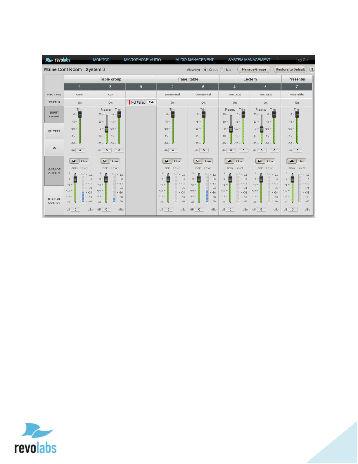
Microphone Audio Page
The microphone audio page allows setting audio parameters for each
microphone individually. The page is structured into two areas. The top area
is set up for adjusting the input signal, and processing the signal by applying
filters, and EQ settings to the audio. The bottom of the table is focused on
output signal and an output gain stage as well as the microphone/line level
setting for the analog audio output.
Input Signal
The Input Signal area allows trimming the input signal for each microphone
separately, allowing for input levels of different microphones to be optimized
individually.
For XLR and TA4 adapters, an additional pre-gain stage is offered. The
Revolabs microphones (omni-directional, directional, gooseneck, and wearable)
are set to provide signals on the same level with a focus on providing the best
signal to noise ratio with the lowest risk of clipping of audio. XLR and TA4
adapters’ third party microphone elements are provided by the customer. The
pre-gain stage is provided to enable greater control over leveling the analog
signal of these microphones for highest signal levels without clipping. Please
ensure that signals are correctly set based on the microphone elements used
with these adapters.
Page 45

45
Filters
Band
Start Frequency
Center Frequency
End Frequency
Low
100 Hz
150 Hz
250 Hz
Low-mid
250 Hz
489 Hz
1,000 Hz
Mid-hi
1,000 Hz
1,739 Hz
3,000 Hz
Hi
3,000 Hz
4,450 Hz
6,000 Hz
High-Pass and Low-Pass filters are provided to adjust to room and application
requirements. Use the High-Pass filter in rooms that have a high background
noise in the low frequencies (air conditioning, lighting fixtures, etc.). The LowPass filter allows limiting high frequencies, based on the applications used. All
filters are bi-quad filters, reducing the signal by 6dB per octave.
EQ
The EQ works in four bands.
Gain adjustment is up to +/- 10dB around the center frequency within the
band, with drop-off to 0dB adjustment at the border frequencies.
Analog Output
When selecting “Analog Output”, the VU meter shows the audio signal as
provided to the analog ports. The final gain stage provided here allows gain or
trim to be applied to the signal before it leaves the Executive Elite Base unit.
“Line” level output provides the signal with an additional 20dB gain compared
to the “Mic” level output.
Digital Output
The digital output shows VU meters for the output signal as provided over AVB.
No gain stage is offered for the digital output, as it is assumed that the data
will be further manipulated at the receiving component.
Page 46

46
Audio Management
The Audio Management menu houses the Manage Groups and System Audio
pages.
Manage Groups
Microphone groups allow defining different mute behavior between individual
microphones or groups of microphones. Microphones in one Executive Elite
System can be assigned to any number of microphone groups. Each group can
then be assigned a specific mute behavior for that group. Using the Cluster
concept, mute groups can be extended across several Executive Elite Base
units, to include microphones from different systems. To create mute groups
across several Executive Elite units, the Elite bases need to be connected to an
IP network, and to be part of the same subnet (see page Error! Bookmark not
defined. on how to set up clusters). When adding an Executive Elite base DSP
to an existing Cluster, mute group names will be exchanged between the
system that was added and the systems priviously in the Cluster ensuring that
all systems in the cluster have the same mute groups.
NOTE: Up to 10 Mute groups can be created within one Executive Elite
base DSP or Cluster. If several Executive Elite Clusters or nonclustered Executive Elite Base DSPs are on the same network or
using the same synchronization bus, the Mute Groups in each of
these Clusters and unclustered Executive Elite Base DSPs are
independent of each other and do not affect the maximum number
of mute groups in each Cluster or Base DSP.
NOTE: To find other units in the same cluster, Executive Elite units
communicate over the IP network using port 5001. While this port
is typically blocked in routers and firewalls going in and out of a
corporate network, you should ensure that this port is open inside
your network, but closed going out of your network.
Executive Elite bases that are assigned to the same cluster and that are in the
same subnet will communicate mute information between each other. Groups
by the same name on different Executive Elite bases in the cluster are
automatically assumed to be the same group, so when mute information is
being exchanged between these bases, mute changes to the same-named
groups will affect microphones on both Elites.
All Executive Elite base DSP units have one group called “Default” which
contains all microphones of a newly configured system.
Page 47

47
1
2 3 4 5 6
7
The Manage group screen shows a list of the groups defined for this system on
the left, and the currently active group on the right side.
Pressing the “+” sign (1) in the top left of the right column will create a new
group. A group name needs to be entered to create the group. Each Executive
Elite Base DSP unit and therefore every Base DSP cluster can have up to 10
mute groups within that cluster. Delet mute groups that are no longer
required in your installation.
To manage and change a group, the group needs to be the active group on the
right side of your screen. The group name of the active group is shown in the
Group field (2). To select a different group as the active group either select it
from the drop-down in the Group field in the right column, or click on the
“Edit” button (3) of that group in the left column. The group will now be
opened on the right side of the screen.
To delete the active group click on the trash can symbol (4). The only group
which cannot be deleted or renamed is the “Default” group.
To change the name of the active group click on the pen symbol (5) and enter
the new name.
Page 48

48
Once a group is active for management microphones can be added to it. Select
any microphone currently in another group listed in the left column, and drag
it over to the right column to add it to the active group.
To remove a microphone you can mouse over the microphone you want to
remove, and click the “x” symbol on the top right, automatically adding that
microphone to the “Default” group.
To define the mute behavior for the active group select the mute behavior from
the Mute Type drop down list(6), see page 94 for information on the different
mute group options.
The “Unmute at Startup” checkbox (7) next to the Mute Type menu determines
whether microphones start unmuted when linking to the base, or muted.
Chairman microphones provide a separate level of control to one microphone in
a group. Independent of the selected mute group behavior, the chairman
microphone in any group can mute all other microphones in that group. A
chairman mute cannot be undone by the non-chairman microphones. The
chairman has to unmute the group before the mute button on the other
microphones can control the mute behavior again.
Chairman mute passes through three stages. First, the chairman mutes all
microphones except itself. Touching the mute area again, all microphones in
the group, including the chairman, are being muted. The next touch on the
mute area will unmute all microphones.
When the group is not in Chairman Microphone mute, the microphones react
as defined in the mute setting for the group.
To select a chairman microphone, move the mouse to hover over that
microphone and the chairman symbol will appear under the microphone.
Click on the chairman symbol to make that microphone chairman. To remove
chairman rights from that microphone, click on the symbol again.
When selecting a microphone as the chairman, mute settings for the group will
automatically change to “Individual Mute” and “Unmute at Startup”. These
settings can be changed afterwards if required.
Only one chairman microphone may exist in any one group. Setting another
microphone in the group as chairman will revoke the previous chairman’s
rights and transfer it to the new chairman microphone. Similarly, only one
chairman can be active in groups shared across a Cluster. If a chairman is
located on another base in the cluster, it will be listed next to the Chairman
icon in the active group header, followed by @<its Elite MAC Address>.
Page 49

49
System Audio Settings
The System Audio Settings Page allows selecting the audio compression in the
system, as well as selecting back channel audio and the source for the back
channel audio.
Microphone audio can either be Standard definition (SD), or High Definition
(HD). HD audio provides double the bit rate for audio transfer over the wireless
link per microphone.
Back channel audio is audio delivered to a wearable microphone or TA4
adapter. If back channel audio is selected, it will be of the same audio format
as the microphone audio. In applications where the back channel audio is not
required it can be switched off, allowing the RF space to be used more
efficiently and increase the maximum number of microphones that can be used
in that environment. If back channel audio is provided, the source for that
audio needs to be defined. It can come either from the analog audio-in ports
on the base or through AVB audio in.
The web page does provide information on the expected number of
microphones that can be active in the selected audio mode in one room. This
number does not take into account other Revolabs systems and microphones
already in use, or other DECT equipment in vicinity. See page 55 on how to
use the RF spectrum for actual RF traffic in the DECT space, and its impact on
the use of Executive Elite microphones.
Page 50

50
NOTE: Systems in vicinity of each other, and either connected via a
synchronization bus, synchronizing via AVB, or synchronizing over
the air, should all use the same System Audio settings. Max
Microphone availability will be significantly reduced if different
settings are being used.
Legacy mode should be used if the Executive Elite Base is connected via the
synchronization bus to an Executive HD unit. Legacy will not allow disabling
the back channel audio.
System Management
The System Management section of the local web user interface contains
information on the Executive Elite system and its components, as well as
system settings. The various submenus are described below.
System Information
The System Information page provides information on the Executive Elite’s
components.
“General Info” displays the System Name, the serial number, and the base
firmware version.
The “Remote Antenna Receiver” section shows the antenna’s MAC Address,
DECT IDs for the 2 (Executive Elite 4 microphone system) or 4 (Executive Elite
8 microphone system) basebands (antennas), and the antenna firmware
version. This section also includes information on whether the antenna is
currently connected or not.
Across the middle of the page, microphones are listed by channel, from 1 to 4
or 1 to 8 based on the number of microphones supported by the system, with
their microphone type, DECT ID, and the current firmware version provided. A
channel with no microphone paired will show no information.
“Connected Units in Cluster” shows the IP Address of any other Executive Elite
base DSP units in the subnet that share the same cluster name. The cluster
name can either be set during the initial setup wizard, or on the System
Configuration page described in the next section.
The “Base Digital Signal Processing Unit” table displays the Base’s IP Address,
MAC Address, and the static IP Address used by the USB port on the front of
the base. Any changes made to this information through the Network
Management page will be displayed here.
“AVB Information” shows the system’s AVB MAC Address, AVB sync mode, the
IP Address of the Internal, or clock master, and if the link is up or down. If
Page 51

51
AVB is not connected, the Link Status will show “Down” and there will be no
Master IP Address.
System Configuration
The System Configuration page allows setting several of the system
configuration values, including system name, cluster name, and region.
Changes to any entry on this web page only take effect when clicking the Save
button. Leaving the page without previously saving changed information will
discard the changes.
System Name allows changing the descriptive name under which a system is
being identified. It is recommended to select a name that helps identifying a
system in the cloud web UI or in a cluster.
The Cluster name allows grouping several Executive Elite systems together for
larger installations. Executive Elite Systems using the same cluster name in a
subnet share group and microphone mute information, allowing common mute
behavior to be defined across several Executive Elite systems. Every Executive
Elite base intended to be in that cluster has to use the exact same cluster
name. To remove a base from a cluster, delete the cluster name and leave the
cluster name field empty. To make the Executive Elite base part of a different
cluster, simply enter the name of that cluster in the field. An Executive Elite
base DSP can only be part of one cluster at a time.
Page 52

52
To reset the system password used on the front panel user interface and the
local web interface enter the new password in the password field, and confirm
it in the confirm password field before saving. The password needs to be
numeric, and has a minimum length of 4 digits.
The Enable Telnet Server setting will enable or disable telnet access to the
Base. Please note that if this setting is set to ‘Off’ the Telnet option for servers
on the External Control Page will not function.
Selecting “Base Pairing Lock” will disable the pairing functionality from the
system’s front panel. Even if Base Pairing is not locked, the front panel
requires the password before allowing pairing of microphones.
In installations where several Executive Elite systems are in proximity, the
systems need to be synchronized to allow for best usage of the RF space and
highest number of active microphones at the same time. The “System Clock”
section sets up and controls synchronization.
Clock Source allows a user to specify which transport is used for the
synchronization. Local means that the system is a stand-alone system not
synchronizing with any other system. Serial means that the 3-wire bus is used
for synchronization between different systems. AVB indicates that the AVB
network is used for synchronization between the Executive Elite systems. And
finally OTA3 shows that synchronization is achieved over the air between the
remote antennas in an installation.
The Clock Mode drop down menu allows specifying the clock source. Internal
sets this Executive Elite system as the clock source. External indicates that a
different connected system is the clock source, and Automatic allows the
Executive Elite Systems to check if it is receiving an external clock or if it
should be providing one.
3
Available in Version 1.2
Page 53

53
Network Management
On this page Network Information for the Executive Elite is organized for easy
access and management.
The DHCP section allows enabling or disabling DHCP on the Executive Elite
base DSP. If DHCP is enabled, the Executive Elite base DSP will request an IP
address from your DHCP server.
If DHCP is disabled, the IP section allows setting a static IP Address and other
network information. While DHCP is enabled, these fields cannot be accessed
and changed; enabling DHCP will delete any data previously entered into the
static address fields.
It is important that this information be filled out correctly before saving
changes, as otherwise the Executive Elite system will not be accessible through
the IP connection.
NOTE: If the network settings are configured incorrectly it can cause the
Elite to become disconnected from the network, making access to
the Web UI over the LAN impossible, even to fix the network
configuration settings. However, the Web UI can still be accessed
from the USB port on the front panel of the Elite. Connect your
computer with the Executive Elite base’s front panel USB port
using a micro USB cable. If required, the operating system will
install driver software on your computer. After that is complete go
into the menu on the Front Panel LCD, where a popup should have
Page 54

54
appeared, giving the static IP Address for the USB
connection. Open a web browser and enter the IP Address, then
log into the Web UI. Now you may correct any network settings to
connect the executive Elite base to your IP network.
Below the IP information is the USB IP table. In this table the Static IP address
and the subnet for the USB interface on the front of the Elite base are defined.
In the upper left is the Network Time Protocol (NTP) server table. List the NTP
servers the Elite has access to in this area.
NOTE: The Cloud server requires that the system time on the Executive
Elite base DSP is correct. If the NTP servers listed here are not
reachable for the Pebble system and system time is therefore
incorrect, access to the cloud server will be declined for the system,
and it cannot be managed through the cloud server.
RF Spectrum Analyzer
The Executive Elite’s Remote Antenna receiver has a built in RF Scanner which
can be accessed through the “RF Spectrum Analyzer” page, providing a colorcoded graph of the local RF environment activity.
After clicking the “Start” button in the upper left corner of the page, the graph
will fill in from the right to left. The scan can be stopped at any time by
returning to the page and pressing the “Stop” button, but the information will
Page 55

55
be cleared from memory once the scan has been stopped and the page is
redirected away from. To save the scan result, take a screenshot of the page
before navigating away, and store it using your preferred image editing
application.
If you navigate away from the page while a scan is running, the scan will
continue in the background as other parts of the Web UI are used or even if the
web interface is closed, as long as the antenna or base is not rebooted.
However, only Average and Peak data will be calculated, no graphical data will
be provided for such times.
The red part of the scan represents the percentage of the RF that is currently in
use, the blue is RF space that shows noise, but could be used by the Executive
Elite system, and green represents available RF space. As each snapshot of the
RF environment is added to the graph, the average is calculated and displayed
in a column beside it, and the peak activity so far is displayed next to that.
The table to the right of the graph shows the number of additional microphones
the RF Environment can support at either average or peak activity, calculated
for each of the Executive Elite’s System Audio modes.
While the graph is set up to display information over a 10 minute period, the
longer the scan is allowed to run, the better estimate it can provide on average
and peak activity for the local RF environment. Running the RF scan does not
impact microphone functionality. The scan can run while all microphones are
being used with no impact on audio performance.
RF Power
The power of the broadcast from an Executive Elite’s remote antenna can be
set from the RF Power menu. The higher the RF power, the further
Page 56

56
microphones can be from the base, but the more impact the broadcast will
have on other RF devices in the vicinity.
The different RF power settings provide suggested ranges in feet and meters for
the maximum distance between the remote antenna and the microphones.
While distances are provided in the setting, obstructions in a room do impact
the maximum possible distance. Please keep that in mind when selecting a RF
power level and testing connectivity.
Automatic Power Scaling allows a microphone to detect the RF power coming
from the antenna, and modify its own output. This way, a microphone closer
to the antenna can reduce its RF impact by limiting the RF signal. Automatic
Power Scaling should be enabled in installations that require high transmit
power settings (long distances) and include multiple Executive Elite Systems.
We recommend experimenting with several different RF settings to find the best
one for your RF needs.
External Control Configuration
The External Control menu enables aspects of the Executive Elite to be
controlled through a room control system or supported external DSPs.
When connected to an external DSP, the Elite can grant that device control
over the mute and unmute status of its audio. Supported external DSPs can
be selected from the external Mute drop down as shown below.
Select the Connection Mode used to communicate to the external system. If
Serial connection is selected, select the baud rate from the opening window.
To set up connection to a Control System, the Elite can either be the Server or
the Client. If Telnet is selected and the Executive Elite system is a client, the IP
Address, login information and port number of the Control System (Server)
must be entered.
Page 57

57
Administration
The Administration menu allows administrator level system control.
Under Logging, system logs can be downloaded for advanced system
information. The dropdown menu can be used to choose the minimum severity
logging level of the messages that will be retrieved.
Below that, system configuration settings can be exported and imported.
Importing a configuration will overwrite all currently active settings in this
Executive Elite System. Export and Import can be used to easily duplicate
settings from one Executive Elite Base DSP to another.
On the right hand side of the page, the components of the Executive Elite can
be restarted independently or in groups.
Restart Base Digital Signal Processing Unit will restart the base and the remote
antenna.
Restart Remote Antenna Receiver will force the Remote Antenna only to restart.
Restart All Microphones forces all currently linked microphones to restart.
Finally, Restart All Components forces the Base DSP unit, the Remote
Antenna, and all linked Microphones to restart.
Restore Factory Defaults resets all settings in the Base DSP unit to the factory
defaults, as listed in the table below. A Reset Factory Defaults will restart the
initial installation dialog to collect system name, region, and cluster
Page 58

58
information. Cloud registration information is not deleted as part of the system
reset. If a system was registered before, the cloud registration window will not
open. Microphone pairing information is also not affected by restoring Factory
Defaults, previously paired microphones are still paired to the system. If
microphones are paired, the microphone pairing dialog will not open.
Page 59

59
Factory Default Settings
Web UI Page
Feature
Default Setting
Mic Audio
Preamp Gain (XLR style microphones)
0 dB
Mic Audio
Input Signal Trim
0 dB
Mic Audio
High-Pass filter - all microphones
110Hz
Mic Audio
Low-Pass filter - all microphones
None
Mic Audio
EQ (4 bands) - all microphones
0 dB
Mic Audio
EQ Enabled - all microphones
Off
Mic Audio
Output Level (mic/line level) - all microphones
Line Level
Mic Audio
Analog Output Gain - all microphones
0 dB
Manage Groups
Group
Default
deleted)
Manage Groups
Chairman mic
None
Manage Groups
Group mute type (tabletop, push-to-talk,
individual)
Individual
Manage Groups
Unmute at Startup
Off
System Audio
Legacy Mode
Off
System Audio
Mic Audio (SD, HD)
HD
System Audio
Back Channel Audio (None, SD, HD)
None
System Audio
Back Channel Audio Source (Analog, AVB)
Analog
Sys Config
System Name
<<empty>>
Sys Config
Cluster Name
<<empty>>
Sys Config
Password
7386
Sys Config
Enable / Disable Telnet connection
On
Sys Config
Language
English
Sys Config
Country/Region
keeps previous value
Sys Config
Time Zone
GMT
Sys Config
Base pairing lock
Off
Sys Config
Clock Source (Local, Sync Bus, AVB,OTA)
Local
Sys Config
Clock Mode (Internal, External, Auto)
Internal
Network Mgmt.
DHCP
On
Network Mgmt.
<<empty>>
Network Mgmt.
Subnet Mask
<<empty>>
(all other groups
Static IP Address
Page 60

60
Web UI Page
Feature
Default Setting
Network Mgmt.
Default Gateway
<<empty>>
Network Mgmt.
DNS1
<<empty>>
Network Mgmt.
DNS2
<<empty>>
Network Mgmt.
192.168.10.4
Network Mgmt.
255.255.255.0
Network Mgmt.
NTP Servers (4)
nist1-ny.ustiming.org
RF Power
Automatic (on/off)
Off
RF Power
Max power level
30 - 75 ft.
External Control
Config
External Control Processor
None
External Control
Config
External Mute (on/off)
Off
External Control
Config
Audio channels (1-8; 9-16; 17-24; 25-32)
1-8
External Control
Config
Connection Mode (Serial/Telnet)
Telnet
External Control
Config
Line Speed (9600, 19200, 38400, 57600,
115200)
115200
External Control
Config
<<empty>>
External Control
Config
<<empty>>
External Control
Config
<<empty>>
External Control
Config
<<empty>>
Admin
Set Log level – dropdown
Debug
Online Access
Registered To
keeps previous value
Online Access
Disable/Enable online access
On
Front Panel
Display Contrast
15
Mic Audio
Preamp Gain (XLR style microphones)
0 dB
Mic Audio
Input Signal Trim
0 dB
USB Static IP Address
USB Subnet Mask
nist1-atl.ustiming.org
nist1-sj.ustiming.org
IP Address
Port
Username
Password
Page 61

61
revoCloud Access
To use an Executive Elite through the Cloud Server, it first needs to be
registered. If registration was not completed during the Initial Setup, it can be
registered through the Online Access page.
An unregistered Elite’s revoCloud Access page takes the same appearance as
the registration request page in the Initial Setup wizard. Selecting cancel on
the popup navigates back to the Monitor page.
For a system registered to the Cloud Server, revoCloud Access will lead to a
Cloud Server permissions page instead of the registration page. The Cloud
Server permission page lists the account the system is registered to, and allows
enabling or disabling online access.
To take advantage of the cloud web UI, a system needs to be registered, and
online access needs to be enabled.
Page 62

62
Software Upgrade
The Software Upgrade page offers two different methods to upgrade the
firmware of an Executive Elite system.
1. An Executive Elite system registered to the Cloud Server may use the
“Check for Latest Version” button to search revoCloud for the most
recent version of the product firmware available on the server. If that
release doesn’t match the current firmware on the Executive Elite
system, the Executive Elite will offer to upgrade through the Cloud. This
method will not work if the Executive Elite has not been registered, or
Cloud Server access is disabled.
2. “Browse for Software File” requires a software bundle to exist on a
computer or server the Elite’s Web UI has access to. Browse to the
software file, select it, and the Executive Elite system will load this
version into the system.
For more information on firmware upgrades see page 76.
Page 63

63
revoCloud
The revoCloud Server is a Web Client allowing for remote access and control of
multiple Executive Elites from any computer with an internet connection.
From the revoCloud website, cloudsupport.revolabs.com, Administrators can
check which Executive Elite systems are online and up-to-date, as well as
accessing basic information about each system. Additional functionality will be
added as it becomes available.
NOTE: The revoCloud website is cloudsupport.revolabs.com.
All data exchange between Executive Elite systems and the cloud server is
secure using https protocol on port 443. Communication between the
executive Elite and the Cloud server is restricted to system usage information,
microphone and battery usage information, user access logging, system change
logging, system logging, RF information, and system settings. No audio data is
ever transported to or saved on the Revolabs cloud server.
Page 64

64
Creating a revoCloud Account
To create an account for use on the revoCloud Server, first navigate to the
Cloud Support web page at cloudsupport.recolabs.com. The home page will
provide a box for login information. Click on the “Create New Account” button
in the upper right hand corner.
To create an account, an Organization or account name, email address, and
password are required. Optionally, a User first and last name may be entered
as well. The email address will be required for future logons to the revoCloud
or to register Executive Elite systems to the cloud. After the required
information has been entered, please read and accept the Terms, Conditions,
and privacy Policy, enter the CAPTCHA code and submit the application.
After the application has been submitted, an activation email will be sent to the
email address specified. This email can be re-sent by logging into the
revoCloud using the email and password from account creation, and selecting
the “Re-Send Verification Email” option on the welcoming page.
Page 65

65
The link provided in the verification email will expire 24 hours after the email
was sent, so please verify the account as soon as possible. Once you click on
the link provided in the verification email, you will be forwarded to the
revoCloud web page, where you will see the verification message.
revoCloud Home
After registering a revoCloud account, log in using the email address and
password of the verified account. If no system has been registered to this
account yet, the home page will list that there are no registered systems at this
time.
Registration of systems needs to be initiated from the Executive Elite local Web
UI. Navigate to the “Online Access” page of a system that was previously
configured, or use the Initial Setup wizard of a new system to register the
Executive Elite system to this cloud account.
Page 66

66
Once an Executive Elite system has been registered to the cloud account, the
home page will list the registered systems.
The revoCloud home page lists all Executive Elite systems registered to the
account. Their system name and status as online or offline will appear at all
times. When an Elite is online, that device’s IP Address, firmware version, and
name of the Cluster it belongs to if applicable, will all be shown. Under status,
the revoCloud server will report if the current firmware version on each base is
up to date and display the progress of upgrades that have been started using
the cloud.
From the Home Page, devices can be selected with the checkboxes on the left of
the screen. All selected devices may be upgraded at the same time by selecting
the Upgrade button at the top of the table, while unselected devices will be left
as they are.
Clicking on any system name will open the System Information page for that
system.
Page 67

67
System Information
The System information page provides additional information on any specific
Executive Elite system. Beside the IP address of the system, cluster
information, and the firmware version running on the system, it will also
display the base serial number, the MAC address of the IP connector, and the
run-time since the last start. This page allows remote download of logs from
the Executive Elite. It also allows unregistering the executive Elite system.
Account Management
The link to the Manage Account page is in the upper left-hand corner of the
revoCloud home page. On this page user name, organization or account name,
account email, and password can all be changed.
To update any part of this page enter the new information in the field and save
the updates to the system. “Cancel” will clear any entered information, and
return the user to the home page.
To change the account password, enter the new password in both the
“Password” and “Confirm Password” boxes before choosing the “Update
Account” button. If the passwords entered in the two fields are different a
warning message is displayed, and the password is not changed.
Page 68

68
Serial Control Processor (Room Control Interface)
The Executive Elite Base DSP is capable of being monitored and controlled via
a control system. Communication can either be over the serial port of the
Executive Elite, or over an IP connection. If several Executive Elite Base DSPs
are part of an installation, each requires its own connection to the control
system in order to communicate.
To use the control system API, the External Control Configuration setting the
type of external processor and the connection method has to be defined to
match the external control system’s settings.
Executive Elite supports server mode or client mode for the control interface.
Selecting the right mode is required for correct interoperability with the
connected control system.
When using a control system, the Executive Elite can be configured for external
mute on the External Control Configuration page of the local web UI. When
external mute is On, the Executive Elite base DSP will always pass audio, even
when the microphones show that they are muted. In this case it is the
responsibility of the installer to ensure that mute is performed in an external
component of the installation.
NOTE: Both a control system and DSP cannot be connected to an
Executive Elite Base Station at the same time. When using a
control system and DSP at the same time, connect the Executive
Elite Base DSP to the control system. The external DSP must be
controlled by the control system as well.
Serial Command & Return Strings
The Serial Strings of an Executive Elite Base Station begin with the Argument
and terminates with a Carriage Return. The Command String structure is as
follows:
<Argument> <Command> [ch <Channel #> <Value>] <CR>
The argument is either ‘set’ or ‘get’. A subset of the available commands is
listed below. For a full list of commands visit the “Executive Elite Control
Interface” documentation.
If specific microphone channels are affected by the command, the string ‘ch’ is
followed by the microphone number, and then the value which is sent (‘set’
command).
Page 69

69
All variable changes on any microphone or the Executive Elite Base Station will
result in a Return String. A Return String will begin with “val” and terminate
with a Carriage Return. Return Strings will be received for every value change
that has taken place in the microphones or base station including changes that
are a result of a Command String sent to the Executive Elite Base Station, but
also for changes initiated from the microphone or the web interface or front
panel interface. The Return String structure is as follows:
val <Command> ch <Channel #> <Value> <CR>
Executive Elite’s Command interface is backwards compatible with Executive
HD’s command interface. Control applications written to control HD systems
will also work with Executive Elite systems. The Executive Elite system’s
control interface has to be configured in the same way the Executive HD’s
command interface was configured.
The Command Interface of the Executive Elite has been expanded significantly
with additional and new functionality. These commands will not work with
Revolabs Executive HD systems.
Channel #:
The options for the <Channel#> portion of the serial strings are 1-8 for an
Executive Elite 8, and 1-4 for an Executive Elite 4 system, since each Base
station can only control its own 8 or 4 microphones, respectively. The
<channel#> corresponds to the channel number the microphone is paired to in
the Executive Elite.
A <Channel#> of “A” will control all microphones.
Examples:
The following string would set microphone channel 3 to be the chairman
microphone for its mute group:
Command: set chairmanmic ch 3 1 Return: val chairmanmic ch 3 1
The following strings would turn off all microphones on the Elite:
Command: set shutdownmic ch A Return: val shutdownmic ch A
The following strings would retrieve the battery status of microphone 5 @ 98%:
Command: get batterystatus ch 5 Return: val batterystatus ch 5 98
Page 70

70
String Tables:
Property/Action
Command Format
Description
Response
audioquality
get audioquality
Retrieve the audio
1 - SD, 2 - HD.
val audioquality
audioquality
set audioquality
Configure audio quality
1 - SD, 2 - HD.
val audioquality
backchannel
get backchannel
Retrieve the back
0 - off, 1 - on.
val backchannel
backchannel
set backchannel
Configure back
0 - off, 1 - on.
val backchannel
batterystatus
get batterystatus ch
Retrieve the given
status.
get batterystatus ch
<percentage>
chairmanmic
get chairmanmic ch
Retrieve the given
1 - chairman.
val chairmanmic ch
chairmanmic
set chairmanmic ch
Configure the given
1 - chairman.
val chairmanmic ch
chairmanmicgroup
set
Configure a
val
name>
chairmanmicgroup
get
Get current chairman
val
id>
chairmanmute
get chairmanmute
Retrieve the given
2 - all muted
val chairmanmute
The following table includes a number of the Elite’s commands. Both
Executive HD legacy commands and new generation Executive Elite commands
will work when programing for the Executive Elite. Please consult the Room
Control API document available at
http://www.revolabs.com/support/product-line/executive-elite
for the complete list.
<1/2>
<0/1>
<channel number>
<channel number>
<channel number>
<0/1>
quality setting,
setting,
channel setting,
channel setting,
microphone's battery
microphone's chairman
state,
For response,
0 - non-chairman,
microphone's chairman
state,
0 - non-chairman,
<1/2>
<1/2>
<0/1>
<0/1>
<channel number>
<channel number>
<0/1>
<channel number>
<0/1>
chairmanmicgroup ch
<channel number>
<group name>
chairmanmicgroup
<group name>
ch <channel
number>
microphone in a
certain group to be
chairman mic
mic in the given group.
channel's chairman
mute state.
0 - all unmuted,
1 – members muted,
chairmanmicgroup
ch <channel
number> <group
chairmanmicgroup
<group name> <mic
ch <channel
number> <0/1>
Page 71

71
Property/Action
Command Format
Description
Response
chairmanmute
set chairmanmute
ch <channel
Configure the given
2 - all muted
val chairmanmute
eq
get eq ch <channel
Retrieve the four EQ
the given channel.
get eq ch <channel
<eq2> <eq3> <eq4>
eq
set eq ch <channel
Configure the four EQ
EQ range -10 to 10 db.
val eq ch <channel
groupmutetype
get groupmutetype
Retrieve group mute
2 - Push to talk.
val groupmutetype
groupmutetype
set groupmutetype
Configure group mute
2 - Push to talk.
val groupmutetype
groupstandbymode
get
<groupname>
Retrieve group's
val
<groupname> <0/1>
groupstandbymode
set
Set group standby
2 - toggle.
val
legacymode
get legacymode
Retrieve the legacy
1 - Legacy mode on
val legacymode
mastermutemicgroup
get
Retrieve the given
1 - muted.
val
mastermutemicgroup
set
Configure the given
1 - muted.
val
micgain
set micgain ch
<gain value>
Set gain value in dB,
A.
val micgain ch
<gain value>
micgain
get micgain ch
Get gain value in dB,
A.
val micgain ch
<gain value>
number> <0/1/2>
channel's chairman
mute state.
0 - all unmuted,
1 – members muted,
ch <channel
number> <0/1/2>
number>
number> <eq1> <eq2>
<eq3> <eq4>
<group name>
<group name>
<0/1/2>
groupstandbymode
groupstandbymode
<groupname>
<0/1/2>
values associated with
values associated with
the given channel,
type,
0 - Individual mute,
1 - Tabletop mute,
type,
0 - Individual mute,
1 - Tabletop mute,
standby mode state.
mode,
1 - Enter standby,
0 - leave standby,
number> <eq1>
number> <eq1>
<eq2> <eq3> <eq4>
<group name>
<0/1/2>
<group name>
<0/1/2>
groupstandbymode
groupstandbymode
default 1
mastermutemicgroup
<group name>
mastermutemicgroup
<group name> <0/1>
<channel number>
<channel number>
mode setting value.
0 - Legacy mode off,
group's master mute
state,
0 - unmute,
group's master mute
state,
0 - unmute,
channel number 1-8 or
channel number 1-8 or
<0/1>
mastermutemicgroup
<group name> <0/1>
mastermutemicgroup
<group name> <0/1>
<channel number>
<channel number>
Page 72

72
Property/Action
Command Format
Description
Response
micstandbymode
get micstandbymode
ch <channel number>
Retrieve mic standby
A
val micstandbymode
micstandbymode
set micstandbymode
Set mic into standby
2 - toggle.
val micstandbymode
micstatus
get micstatus ch
Retrieve the given
8 – updating
val micstatus ch
mictype
get mictype ch
Retrieve the given's
11 - unknown
val mictype ch
mutestatus
get mutestatus ch
Retrieve the mic mute
type>,<mute lock>
val mutestatus ch
regnotify
Regnotify
Register to listen to
system notifications.
regnotify
outputgain
get outputgain ch
Retrieve the given
val outputgain ch
<output gain>
outputgain
set outputgain ch
Configure the given
to 5 dB
val outputgain ch
outputlevel
get outputlevel ch
Retrieve the channel
1 - line level.
val outputlevel ch
status,
channel number 1-8 or
ch <channel
number> <0/1>
ch <channel number>
<0/1/2>
<channel number>
<channel number>
mode,
1 - Enter standby,
0 - leave standby,
microphone's current
status,
0 - off,
1 - on,
2 - standby,
3 - charging,
4 - out of range,
5 - not paired,
6 - pairing,
7 - unpairing,
microphone's type.
0 - Wearable,
1 - Omni,
2 - Directional,
3 - XLR,
4 - Mini XLR,
5 - Gooseneck,
10 - Handheld,
ch <channel
number> <0/1>
<channel number>
<status>
<channel number>
<type>
<channel number>
<channel number>
<channel number>
<output gain>
<channel number>
status, value is a
comma delimited
string:
<mute>,<mute
channel's output gain.
channel's output gain,
output gain range -20
output level,
channel number
1/2/../8/A,
0 - mic level,
<channel number>
<mute>,<mute
type>,<mute lock>
<channel number>
<channel number>
<output gain>
<channel number>
<0/1>
Page 73

73
Property/Action
Command Format
Description
Response
preampgain
get preampgain ch
<channel number>
Retrieve the given
val preampgain ch
<preamp gain>
preampgain
set preampgain ch
Configure the given
to 0 dB.
val preampgain ch
pushtotalk
get pushtotalk <group
Retrieve group push to
0 - not set.
val pushtotalk
pushtotalk
set pushtotalk <group
Configure group push
2 - toggle.
val pushtotalk
pushtotalkmic
get pushtotalkmic ch
Retrieve microphone's
0 - not set.
val pushtotalkmic ch
shutdownmic
shutdownmic ch
Power the microphone
shutdownmic ch
tabletopmutegroup
get
Retrieve the given
1 - tabletop mute.
val
tabletopmutegroup
set
Configure the given
1 - tabletop mute.
val
batt
get batt ch <channel
Retrieve battery status
channel.
val batt ch <channel
fp
set fp <0/1>
Set front panel display
0 - Off, 1 – On
val fp <0/1>
gain
set gain ch <channel
Configure input gain,
0 - set gain to 0
val gain ch <channel
gain
get gain ch <channel
number>
Retrieve input gain for
specified channel.
val gain ch <channel
number><80-120>
lock
set lock ch <channel
Turns Mic Lock on or
0 - Off, 1 - On
val lock ch <channel
channel's preamp gain.
<channel number>
<channel number>
<preamp gain>
name>
name> <0/1/2>
<channel number>
<channel number>
tabletopmutegroup
<group name>
channel's preamp gain,
preamp gain range -20
talk setting value,
1 - push to talk set,
to talk setting,
1 - push to talk set,
0 - not set,
push to talk state.
1 - push to talk set,
off.
group's tabletop mute
state,
0 - not tabletop mute,
<channel number>
<preamp gain>
<group name> <0/1>
<group name>
<0/1/2>
<channel> <0/1>
<channel number>
tabletopmutegroup
<group name> <0/1>
tabletopmutegroup
<group name> <0/1>
number>
number> <0/1/2/80120>
number> <0/1>
group's tabletop mute
state,
0 - not tabletop mute,
for mic in specified
lock on or off;
values 80 - 100 set the
gain from -20 to 0 dB
values 101 – 120 will
all set the gain 0 dB
1 - modify gain by +1,
2 - modify gain by -1,
off;
tabletopmutegroup
<group name> <0/1>
number><1/2/3/4>
number>
<0/1/2/80-120>
number> <0/1>
Page 74
74
Property/Action
Command Format
Description
Response
lock
get lock ch <channel
number>
Retrieve Mic Lock for
specified channel.
val lock ch <channel
number> <0/1>
mute
set mute ch <channel
number> <0/1>
Mute or unmute
0 - Unmute, 1 - Mute
val mute ch <channel
mute
get mute ch <channel
Retrieve mute state for
val mute ch <channel
/5>
Notifications
Notification Format
Description
mute_group_change
notify mute_group_change
Notify client that changes
delete, 'ren' - rename.
mute_group_member_change
notify
<mic index>
Notify client that a mic has
mute_group_mute_type_change
notify
Notify client that the given
2 - Push to talk.
set_mute_status
notify set_mute_status
Notify client the given
0 - unlocked, 1 – locked
startup_unmute_group
notify startup_unmute_group
Notify client that the given
0 - mute at startup.
status_change_antenna_link
notify
<status>
Notify client antenna link
0 - unlinked, 1 - linked.
specified channel:
number> <0/1>
number>
specified channel.
number><0/1/2/3/4
Notifications:
The Executive Elite command ‘regnotify’ will turn on notifications.
<group name> <action>
mute_group_member_change
<group name> bid <box id>
active <0/1> type <type> index
mute_group_mute_type_change
<group name> <mute type>
that affect a given group
have occurred. Actions
include 'add' - add, 'del' -
changed its group.
mute group's mute type has
changed,
0 - Individual mute,
1 - Tabletop mute,
ch<channel number>
<mute>,<mute type>,<mute
lock>
<group name> <state>
status_change_antenna_link
microphone's mute status
changed.
<mute> values:
0 - unmuted, 1 - muted
<mute type> values:
0 - Individual Mute,
1 - Tabletop mute,
2 - Push to talk mute
<mute lock> values:
mute group's unmute at
startup setting changed,
1 - unmute at startup,
status changed,
Page 75
75
Notifications
Notification Format
Description
status_change_battery
notify status_change_battery
ch<channel number>
<percentage>
Notify client the given
changes.
status_change_mic
notify status_change_mic
Notify client the given
8 – updating
status_group_mute
notify status_group_mute
Notify client the given
0 - group unmuted.
Batt
val batt
Mic battery status.
3 - 75%, 4 - 100%
Mute
val mute…
Mic mute state;
5 - microphone charging
Type
val type…
Mic type;
5 - Countryman Adapter
microphone's battery status
ch<channel number> <status>
<group name> <group mute
state>
microphone's status
changed,
0 - off,
1 - on,
2 - standby,
3 - charging,
4 - out of range,
5 - not paired,
6 - pairing,
7 - unpairing,
group's mute status
changed.
8 - group muted,
1 - 25%, 2 - 50%,
0 - unmuted,
1 - self muted,
2 - muted,
3 - microphone off,
4 - microphone out of
range,
1 - Lapel
(Wearable),
2 - Omnidirrectional
Tabletop
3 - Directional Tabletop,
4 - XLR Adapter,
Page 76

76
Firmware updates
Executive Elite Firmware can be upgraded two different ways. An Executive
Elite system registered to the revoCloud can be upgraded to the most recent
build from the Cloud Support web page. Select the system on the cloud
webpage, and click on “Upgrade to latest build” to immediately upgrade the
system as described on page 67.
Any system, independent on whether it is registered on the cloud server or not,
can be updated through the Software Upgrade page of the local Web UI. If the
system is registered to the cloud server, the webpage allows checking the Cloud
Server for an upgrade. An unregistered Executive Elite system can be
upgraded from the Web UI using an upgrade software bundle accessible from
the computer connected to the Executive Elite system as described on page 62.
Upgrade bundles are available on Revolabs website in the support section.
Firmware upgrades upgrade all linked components on an Executive Elite
system.
• The Software Download pages show the progress of the Base then Antenna
upgrades, in that order.
• After the upgrade is successful, linked microphones will begin upgrading
over RF. If microphones are not linked, they will begin upgrading the next
time they are linked.
• Microphones in a charger will still upgrade as long as they are paired to the
Elite unit that is upgraded.
• An upgrade of the Base unit and the antenna takes about ten minutes.
• Depending on the System Audio Setting, Microphones can take up to 6
minutes to upgrade. Audio modes in which back-channel audio is disabled
will take longer to update the microphones.
Page 77

77
Microphones
Revolabs Executive Elite offers a wide variety of wireless microphones and
adapters to use with the system:
• Revolabs Elite Wearable Wireless Microphone
• Revolabs Elite Omni-directional Tabletop Wireless Boundary Microphone
• Revolabs Elite Uni-directional Tabletop Wireless Boundary Microphone
• Revolabs Elite 6 inch Tabletop Gooseneck Microphone
• Revolabs Elite 12 inch Tabletop Gooseneck Microphone
• Revolabs Elite Universal Wireless Adapter for Handheld Microphones (XLR
adapter)
• Revolabs Elite Wireless TA4 Adapter (mini XLR adapter)
NOTE: Before using microphones they must be paired to the Base DSP
unit and Remote Antenna. Each microphone is assigned a unique
channel on the Base DSP unit. See pairing instructions below on
how to pair microphones.
NOTE: Replace batteries only with Revolabs approved rechargeable
batteries. Non-approved batteries or rechargeable batteries might
impact performance of the microphone, and might cause harm to
the microphone, users, or the environment. Using non-approved
batteries will void the warranty on the microphones. When
replacing the batteries, ensure that the batteries are placed in the
correct way.
Page 78
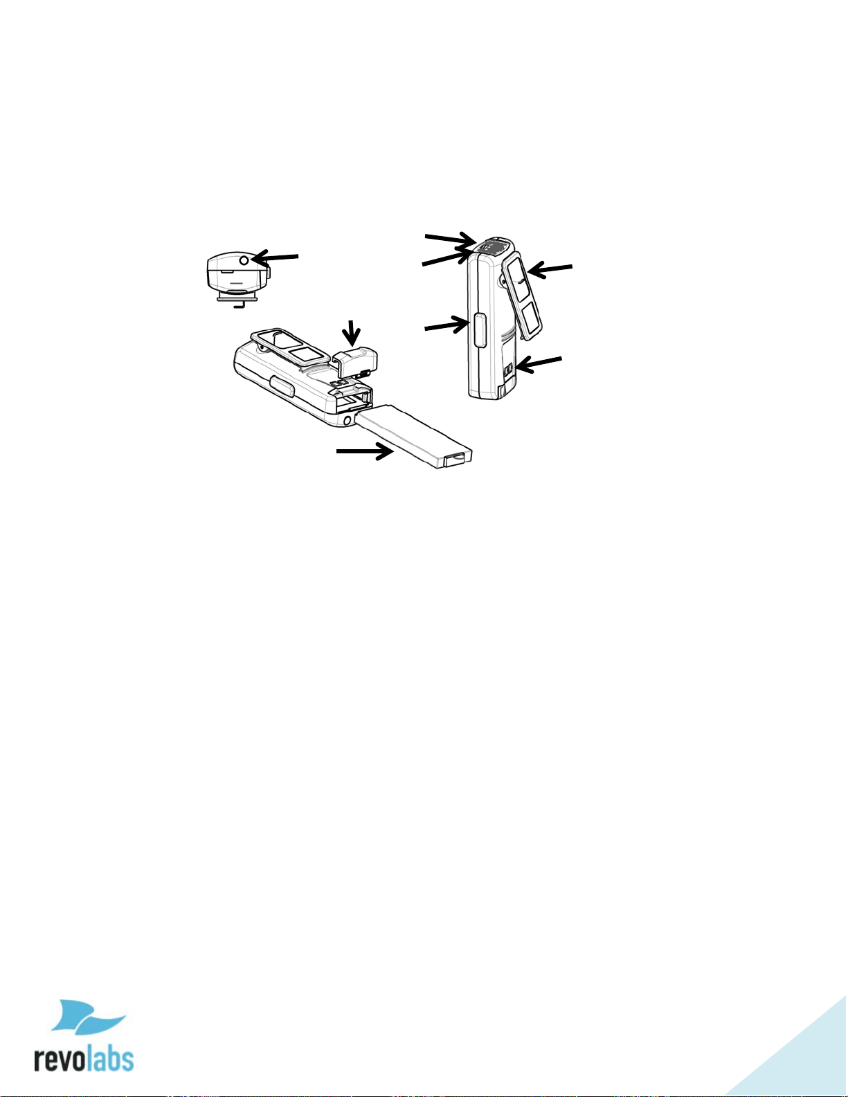
78
The Elite Wearable Wireless Microphones
1 2 3 4 5 6 7
8
The Revolabs Elite Wearable Microphones, shown in the following figure, can
be worn on the user’s shirt, lapel, blouse, or on a lanyard. They provide high
quality full duplex audio between the users and the conferencing or audio
system.
1. Earpiece jack — accepts the 2.5mm plug of the earpiece.
2. Battery door — push towards the back of the microphone to open
the battery compartment.
3. Li-Ion rechargeable battery — can be taken out and replaced after
opening the battery door.
4. Mute LED — visual status for mute, un-mute, and pairing.
5. Battery charge status LED — under the screen, warns for low
battery. When there is approximately 2 hours of talk time
remaining, this LED will turn yellow. When the LED turns red,
there is approximately 1 hour of charge remaining.
6. Mute button — press to mute, un-mute, and pair microphone.
7. Clip — used to attach microphone to a shirt, lapel, blouse or
lanyard.
8. Charging connector — connects to the charging pins of the Elite
charging tray.
Revolabs Elite Wearable Microphones turn on when removed from Charger
Base. To reduce noise while they are being attached, we recommend muting
the microphone when attaching and detaching it.
Page 79
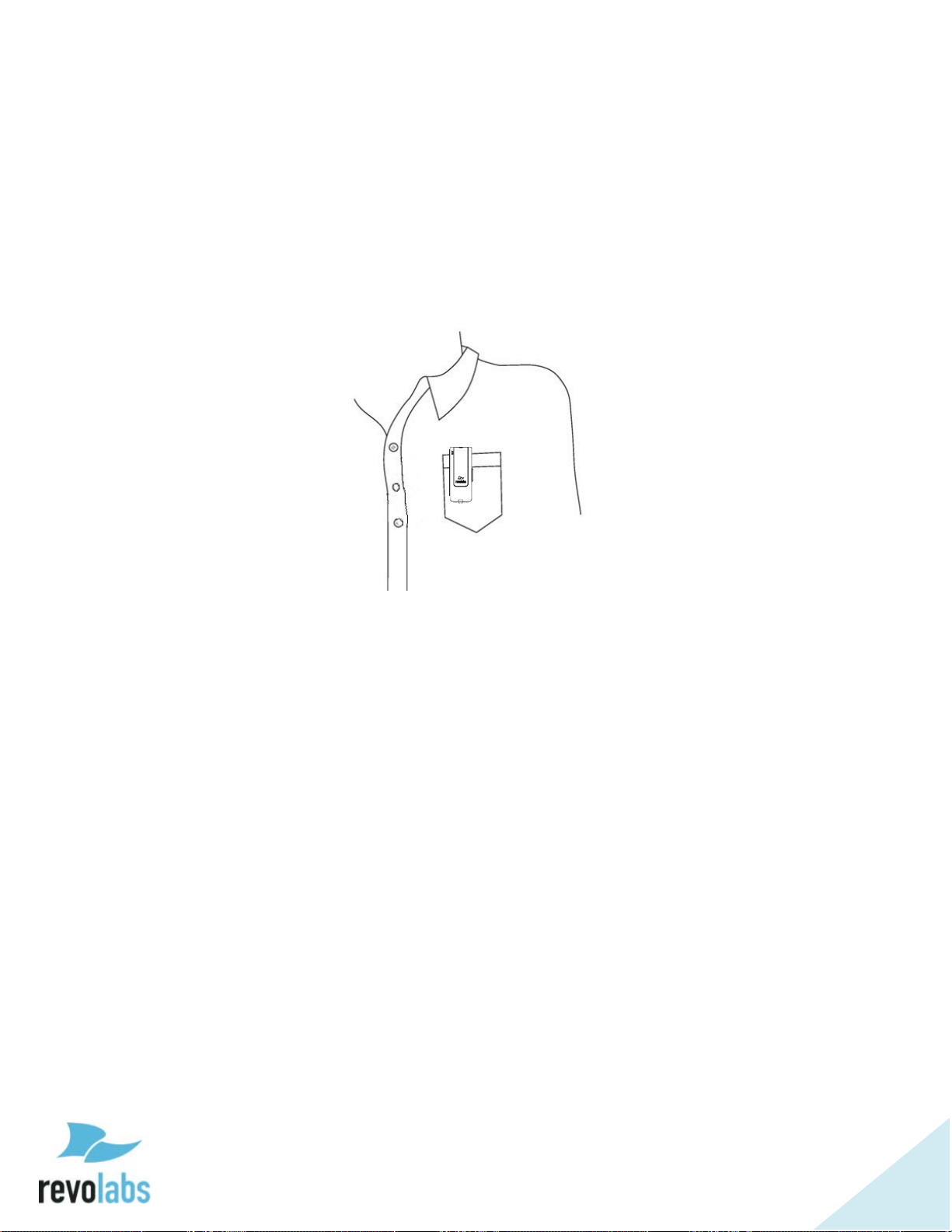
79
To use the Elite Wearable Microphone:
1. Remove the microphone from the Charger Base.
2. Attach the microphone to clothing or to a lanyard, positioning the
microphone just above the sternum or breastbone, within 6 - 12 inches (15
– 30cm) from the mouth. Make sure that the microphone is attached
securely. The Elite wearable microphone utilizes an omni-directional
microphone element, it is therefore not important that the microphone
points up towards the mouth.
3. After positioning the microphone, based on the mute behavior defined for
that microphone un-mute and mute it by pressing and releasing the Mute
button (confirm by a flashing green LED or red LED, respectively). If the
volume is too low, mute the microphone, relocate it closer to the mouth, and
unmute it again.
4. To turn the microphones off, return the microphone unit to the Charger
Base or press and hold the Mute button for about 10 seconds until the LED
turns solid red, then release the button. The microphone can also be
turned off from the local web UI or the room control interface. Note that, in
push to talk mode the microphone cannot be shut down using the mute
button.
If the microphones are moved out of range of the Remote Antenna (depending
on the RF power setting this can be 300 feet, 90 meters, or more from the
Remote Antenna), the connection will be dropped, the LED flashes red, yellow,
green, yellow, and the microphone will mute.
After 15 seconds the microphone will beep, and will continue beeping every 30
seconds to remind the user to return the microphone to the conference room. If
the microphone is moved back into range of the Remote Antenna within 15
minutes the connection will automatically be re-established to its original state,
and the beeping will cease. If not, the microphone will turn off.
Page 80

80
Adjusting the Volume on the Wearable Microphone Earpiece
To change the volume on the Wearable microphone earpiece, use the dial on
the earpiece wire.
Turning the dial as shown in the figure will increase decrease the volume. Use
the attached clothing clip to secure the earpiece wire.
Page 81

81
The Elite Omni-Directional Wireless Tabletop Boundary
1 2 3
4
5
Microphones
The Elite Omni-directional Wireless Tabletop Boundary Microphones enable
multiple conference attendees to use a single microphone.
1. Mute touch areas & LEDs — touch to mute, un-mute, or pair the
microphone. LEDs provide visual status for mute, un-mute, and pairing.
The omni-directional microphone provides four mute touch areas and status
LEDs, one on each side of the microphone. Any one of these touch areas
may be used to mute and unmute the microphone.
2. Charging connector — connects to the charging pins of the Elite charging
tray or crossover adapted.
3. Battery door latch — open the battery door using this latch.
4. Rechargeable batteries — replace batteries only with NiMH 2000mA
rechargeable batteries. Non-rechargeable batteries or rechargeable batteries
of a different type or lower charge might impact performance of the
microphone, and might cause harm to the microphone, users, or the
environment. Using non-approved battery types will void the warranty on
the microphones. When replacing the batteries, ensure that the batteries
are placed in the correct way as indicated by the print in the battery cavity
of the microphone.
5. Battery charge status LED — under the screen, warns for low battery. The
LED will turn yellow when there are 4 hours of talk time remaining and red
for the last two hours of charge.
Page 82

82
To use the Elite Omni-Directional Tabletop Microphone:
1. Remove the microphone from the Charger Base. The microphone will
automatically turn on. Based on settings in the Base DSP, the microphone
will start either un-muted or muted, indicated by green or red blinking
lights, respectively.
2. Omni Tabletop microphones can be centered on the table within 2 to 6 feet
(0.6 to 2m) away from people speaking and do not need to be pointing any
particular direction because they pick up sound from all directions. It is
always better to place a microphone as close to the people speaking as
possible, while avoiding placing the microphone where it might be blocked
by equipment or paperwork. Do not place microphones too close to an
audio or video conference speaker to avoid echoes. Make sure that the
microphone’s rubber feet are sitting atop a flat surface.
3. With the microphone in position on the table, see picture above for an
example, mute or un-mute the microphone by touching any of the four
mute areas (confirm by flashing green or flashing red LEDs, respectively). In
push-to-talk mode, touch a mute area and keep the finger there to unmute
the microphone. Removing the finger from a touch area will mute the
microphone.
4. To turn the microphone off, return it to the Charger Tray or touch and hold
any of the Mute areas for about 10 seconds until the LEDs turn solid red,
then remove the finger from the touch area. The microphone can also be
turned off from the local web UI or the room control interface. In push to
talk mode the microphone cannot be shut down using the mute areas.
If the microphones are placed too far away from the Remote Antenna
(depending on the RF power setting this can be 300 feet, 90 meters, or farther
from the Remote Antenna) the connection will be dropped (LEDs flash redyellow-green-yellow) and the microphone will mute. After 15 seconds the
microphone will beep, and will continue beeping every 30 seconds to indicating
that it is out of range.
Move the microphone closer to the Remote Antenna and the connection will
automatically be re-established to its original state, and the beeping will cease.
Otherwise, the microphone will continue beeping until it turns off after about
15 minutes.
Page 83
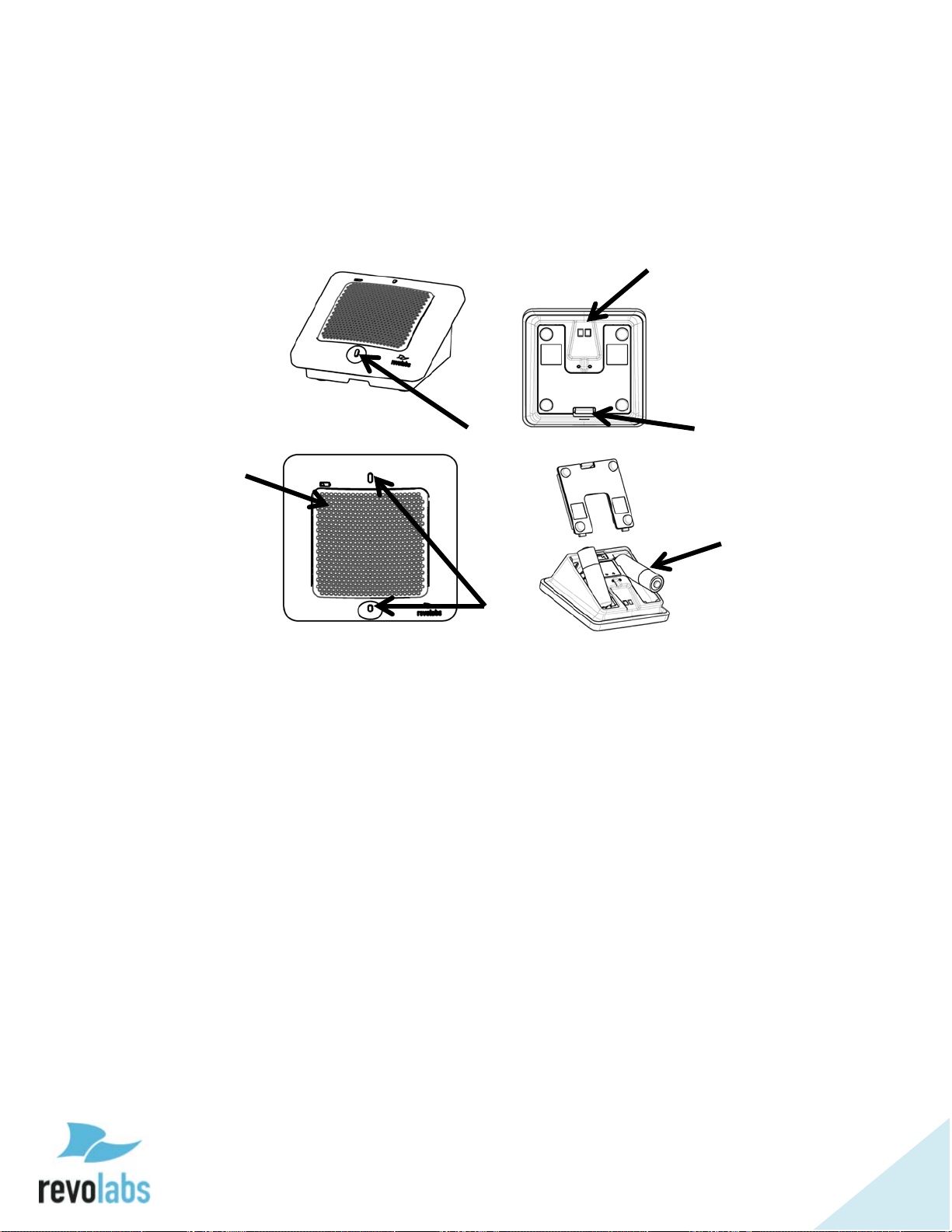
83
The Elite Directional Wireless Tabletop Boundary
1
2
3
4
5
6
Microphones
The Elite Directional Wireless Tabletop Boundary Microphone, shown below, is
designed to provide optimum coverage when placed on a conference room table
in front of one to three people.
1. Mute touch area — touch to mute, un-mute, or pair the microphone. The
directional microphone provides one mute touch area on the edge closest to
the speaker.
2. Charging connector — connects to the charging pins of the Elite charging
tray or crossover adapter.
3. Battery door latch — open the battery door using this latch.
4. Rechargeable batteries — replace batteries only with NiMH 2000mA
rechargeable batteries. Non-rechargeable batteries or rechargeable batteries
of a different type or lower charge might impact performance of the
microphone, and might cause harm to the microphone, users, or the
environment. Using non-approved battery types will void the warranty on
the microphones. When replacing the batteries, ensure that the batteries
are placed in the correct way as indicated by the print in the battery cavity
of the microphone.
5. Battery charge status LED — under the screen, warns for low battery. The
LED will turn yellow when there are 4 hours of talk time remaining and red
for the last two hours of charge.
6. Status LEDs — provide visual status for mute, un-mute, and pairing.
Page 84
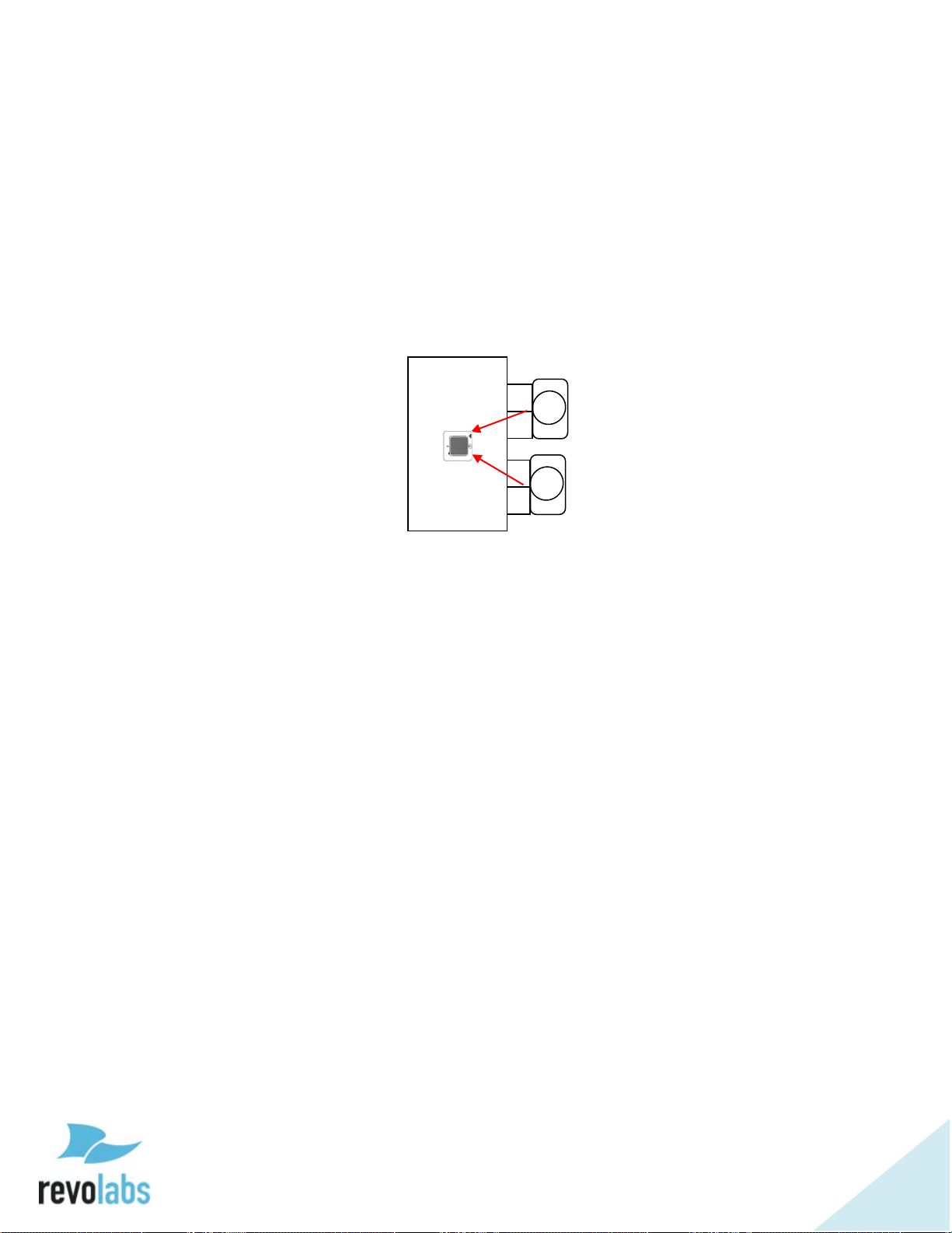
84
To use the Elite Directional Tabletop Microphone:
1. Remove the microphone from the Charger Base. The microphone will
automatically turn on. Based on settings in the Base DSP, the microphone
will start either un-muted or muted, indicated by green or red blinking
LEDs, respectively.
2. Directional Tabletop microphones should be located on the table with the
metal screen facing toward the users, trying to keep the microphone 2 to 6
feet (0.6 to 2m) from the target people. The pick-up pattern for this
directional microphone is approximately +/- 65º to either side of directly in
front of the microphone. Refer to the diagram below:
It is always better for the microphone to be as close to the person speaking
as possible, but avoid placing the microphone where it might be blocked by
equipment or paperwork. Avoid placing microphones too close to an audio
or video conference speaker to avoid echoes. Make sure the microphone is
sitting on its rubber feet, and not on its side.
3. With the microphone in position on the table, see picture above for an
example, mute or un-mute the microphone by touching the mute area
(confirm by flashing green or flashing red LEDs, respectively). In push-totalk mode, touch the mute area and keep finger there to unmute the
microphone. Removing finger from a touch area will mute the microphone.
4. To turn the microphone off, return it to the Charger Base or touch and hold
the Mute touch area for about 10 seconds until the LEDs turn solid red,
then remove the finger. The microphone can also be turned off from the
local web UI or the room control interface. In push to talk mode the
microphone cannot be shut down using the mute area.
If the microphones are placed too far away from the Remote Antenna
(depending on the RF power setting this can be 300 feet, 90 meters, or more)
the connection will be dropped (LEDs flash red-yellow-green-yellow) and the
microphone will mute. After 15 seconds the microphone will beep, and will
continue beeping every 30 seconds to indicate that it is out of range.
Move the microphone closer to the Remote Antenna and the connection will
automatically be re-established to its original state and the beeping will cease.
Otherwise, the microphone will continue beeping until it turns off after about
15 minutes.
Page 85

85
The Elite Wireless 6 inch and 12 inch Wireless
2 3 1 4 5 6 7
Gooseneck Tabletop Microphones
The Elite Wireless 6 inch and 12 inch Wireless Gooseneck Tabletop
Microphones, shown below, are designed to provide optimum coverage when a
personal microphone is being assigned for each participant in the meeting or
panel.
1. Mute touch area & LED — touch to mute, un-mute, or pair the microphone.
LED provides visual status for mute, un-mute, and pairing.
2. Charging connector — connects to the charging pins of the Elite charging
tray or crossover adapter.
3. Battery door latch — open the battery door using this latch.
4. Rechargeable batteries — replace batteries only with NiMH 2000mA
rechargeable batteries. Non-rechargeable batteries or rechargeable batteries
of a different type or lower charge might impact performance of the
microphone, and might cause harm to the microphone, users, or the
environment. Using non-approved battery types will void the warranty on
the microphones. When replacing the batteries, ensure that the batteries
are placed in the correct way as indicated by the print in the battery cavity
of the microphone.
5. Battery charge status LED — warns about low battery.
6. Additional LED — provides visual status for mute, un-mute, and pairing.
7. Flexible microphone stem — use to position microphone facing the desired
direction.
Page 86

86
To use either of the Elite Gooseneck Tabletop Microphones:
1. Remove the microphone from the Charger Base. The microphone will
automatically turn on. Based on settings in the Base DSP, the microphone
will start either un-muted or muted, indicated by green or red blinking
lights, respectively.
2. Gooseneck Tabletop microphones should be located on the table with the
microphone pointing toward the user, trying to keep the microphone 18 to
24 inches (45 to 60 cm) from the speaker. The pick-up pattern for this
directional microphone is cardioid, focusing a “beam” towards the speaker.
It is always better for the microphone to be as close to the person speaking
as possible, but avoid placing the microphone where it might be blocked by
equipment or paperwork. Avoid placing microphones too close to an audio
or video conference speaker to avoid echoes. Make sure that the microphone
is always placed standing on its rubber feet atop a flat surface. Refer to the
diagram below:
3. With the microphone in position on the table, see the picture above for
example, mute or un-mute the microphone by touching the mute area
(confirm by flashing green or flashing red LEDs, respectively). In push-totalk mode, touch the mute area and keep the finger there to unmute the
microphone. Removing the finger from the touch area will mute the
microphone again.
4. To turn the microphone off, return it to the Charger Tray or touch and hold
the Mute touch area for about 10 seconds until the LEDs turn solid red, and
remove the finger. The microphone can also be turned off from the local
web UI or the room control interface. In push to talk mode the microphone
cannot be shut down using the mute area.
If the microphones are placed too far away from the Remote Antenna
(depending on the RF power setting this can be 300 feet, 90 meters, or more)
the connection will be dropped (LEDs flash red-yellow-green-yellow) and the
microphone will mute. After 15 seconds the microphone will beep, and will
continue beeping every 30 seconds to indicating that it is out of range.
Move the microphone closer to the Remote Antenna and the connection will
automatically be re-established to its original state, and the beeping will cease.
Otherwise, the microphone will continue beeping until it turns off after about
15 minutes.
Page 87

87
1 4 3 2 5
6
7
8
Elite Wireless XLR Adapter
The Elite Wireless XLR Adapter allows dynamic hand-held microphones to be used
with an Executive Elite system.
1. Earpiece jack — accepts a 2.5mm earpiece plug.
2. Battery door — push towards the back of the microphone to open
the battery compartment.
3. Li-Ion rechargeable battery — can be taken out and replaced after
opening the battery door. Replace batteries only with Revolabs
approved rechargeable batteries.
4. Battery charge status LED — warns for low battery. When there is
approximately 2 hours of talk time remaining, this LED will turn
yellow. When the LED turns red, there is approximately 1 hour of
charge remaining.
5. Mute LED — visual status for mute, un-mute, and pairing.
6. Mute button — press to mute, un-mute, and pair microphone.
7. Charging connector — connects to the charging pins of the Elite
charging tray.
8. XLR connector — male XLR connector, connecting to dynamic XLR
handheld microphones.
Page 88

88
To use the Elite Wireless XLR Adapter:
1. Remove the wireless adapter from the Charger Base.
2. Attach a dynamic handheld microphone to the adapter, following safety
precautions and user information provided with that microphone.
3. After positioning the microphone at the distance it will be used at, unmute
it and go to the Microphone Management page of the Web UI. The XLR
adapter’s column will have a Pre-Amp gain setting once the adapter is
paired. This slider will allow different types of microphones to be integrated
with the Executive Elite system. Select the highest setting on the pre-amp
where clipping is not observed, to allow for the highest signal to noise ratio.
4. Based on the mute behavior defined for the adapter in the local web UI,
mute or un-mute the microphone by pressing the mute button on the
adapter (confirmed by flashing green or flashing red LEDs, respectively). In
push-to-talk mode, press the mute button and keep the finger there to
unmute the microphone. Removing the finger from the mute button will
mute the microphone again.
5. To turn the XLR adapter off, return the unit to the Charger Base or press
and hold the Mute button for about 10 seconds until the LED turns solid
red, then release button. The adapter can also be turned off from the local
web UI or the room control interface. In push to talk mode the adapter
cannot be shut down using the mute button.
NOTE: Do not place the XLR adapter into the Charging base while the
handheld microphone is still attached. Place only the adapter in
the charging Base.
NOTE: The XLR adapter does not provide phantom power. Use only
dynamic hand-held microphones with the adapter.
If the adapters are placed too far away from the Remote Antenna (depending on
the RF power setting this can be 300 feet, 90 meters, or more from the Remote
Antenna) the connection will be dropped (LEDs flash red-yellow-green-yellow)
and the microphone will mute. After 15 seconds the adapter will beep, and will
continue beeping every 30 seconds to indicating that it is out of range.
Move the adapter closer to the Remote Antenna and the connection will
automatically be re-established to its original state, and the beeping will cease.
Otherwise, the adapter will continue beeping until it turns off after about 15
minutes.
Page 89

89
1 2 3 4 5
6 6 7 8 9
The Elite Wireless TA4 (mini XLR) Adapter for lapel and ear-set microphones
The Elite Wireless TA4 (mini XLR) Adapter allows small lapel or over-the-ear
microphones to be used with an Executive Elite system.
1. Earpiece jack — accepts a
2.5mm earpiece plug.
2. Battery door — push towards
the back of the microphone to
open the battery
compartment.
3. Li-Ion rechargeable battery —
can be taken out and replaced
after opening the battery
door. Replace batteries only
with Revolabs approved
rechargeable batteries.
4. Battery charge status LED —
warns for low battery. When
there is approximately 2
hours of talk time remaining,
this LED will turn yellow.
When the LED turns red,
there is approximately 1 hour
of charge remaining.
5. Mute LED — visual status for mute, un-mute, and pairing.
6. Mute button — press to mute, un-mute, and pair microphone.
7. Clip — used to attach adapter to clothing or a belt.
8. Charging connector — connects to the charging pins of the Elite charging
tray.
9. TA4 (Mini XLR) connecter — use to connect a lapel or over-the-ear
microphone to the TA4 adapter. See picture below for the wiring of the
TA4 adapter.
Page 90

90
NOTE: Use only microphones compatible with the wiring of the TA4
adapter.
NOTE: The TA4 adapter provides 2.7 volts of phantom power.
To use the Elite Wireless TA4 (mini XLR) Adapter:
1. Remove the mini XLR Adapter from the Charger Base.
2. Attach a microphone to the top of the adapter and clip the end to clothing or
a belt. Make sure that the microphone and adapter are attached securely.
3. After positioning the microphone at the distance it will be used at, unmute
it and go to the Microphone Management page of the Web UI. The TA4
adapter’s column will have a Pre-Amp gain setting once the adapter is
paired. This slider will allow different types of microphones to be integrated
with the Executive Elite sound system. Select the highest setting on the
pre-amp where clipping is not observed, to allow for the highest signal to
noise ratio.
4. Based on the mute behavior defined for the adapter in the local web UI,
mute or un-mute the microphone by pressing the mute button on the
adapter (confirmed by flashing green or flashing red LEDs, respectively). In
push-to-talk mode, press the mute button and keep the finger there to
unmute the microphone. Removing the finger from the mute button will
mute the microphone again.
5. To turn the mini XLR adapter off, return the unit to the Charger Base or
press and hold the mute button for about 10 seconds until the LED turns
solid red, then release the button. The adapter can also be turned off from
the local web UI or the room control interface. In push to talk mode the
adapter cannot be shut down using the mute button.
NOTE: Do not place the TA4 adapter into the Charging Base while the
handheld microphone is still attached. Place only the adapter in
the Charging Base.
If the adapter is placed too far away from the Remote Antenna (depending on
the RF power setting this can be 300 feet, 90 meters, or more from the Remote
Antenna) the connection will be dropped (LEDs flash red-yellow-green-yellow)
and the microphone will mute. After 15 seconds the adapter will beep , and will
continue beeping every 30 seconds to indicating that it is out of range.
Move the adapter closer to the Remote Antenna and the connection will
automatically be re-established to its original state, and the beeping will cease.
Otherwise, the adapter will continue beeping until it turns off after about 15
minutes.
Page 91

91
Batteries
Replace batteries in the microphones only with Revolabs approved batteries!
The tabletop microphones require standard Nickel Metal Hydrate NiMH
rechargeable batteries with a 1.2 V voltage and a charge capacity of 2000mAh.
Example batteries following these specifications are Sony NHAAB4KN or
Panasonic HHR-210AAB.
Revolabs warranty is voided if a battery is used that
• uses a different battery technology than rechargeable NiMH batteries,
• uses a battery with a different voltage than the required 1.2V,
• uses a battery with a different charge capacity than the required 2000 mAh.
The wearable microphone, as well as the XLR and TA4 adapters use a custom
Li-Ion rechargeable battery. Use only Revolabs provided batteries for these
microphones. Using any other battery will void Revolabs warranty.
Caution: Risk of explosion if batteries are mishandled or replaced by an
incorrect type. Do not disassemble batteries or attempt to charge outside the
system. Do not dispose of batteries in fire. Dispose of batteries in accordance
with manufacturer’s instructions and local regulations.
Pairing Wireless Microphones to Remote Antenna and Base DSP Station
Pairing creates a link between the Elite wireless microphone and the Base DSP
Unit through the Remote Antenna with a unique electronic serial number.
When the microphone and Base DSP Station have been previously paired, the
microphone will automatically try to connect (“link”) to the same Base DSP Unit
whenever it is lifted from the Charger Tray.
NOTE: New microphones in a system must be paired to the Base DSP Unit
with each microphone assigned to a unique channel on the base
unit.
NOTE: The microphone needs to be in range of the Remote Antenna
during the pairing process. Pairing is done wirelessly, the
microphone communicates through the Remote Antenna to the
Base DSP Unit during pairing.
A microphone that is not paired will be indicated by a cycling red-green LED
pattern. A Base DSP Unit channel that is not paired to a microphone will not
Page 92

92
show any activity on the channel LED and front panel LCD, and will be shown
as “Not Paired” on the web interfaces.
During pairing, the microphone LEDs and the channel LED on the front of the
Base DSP Unit will stay solid red.
Only one microphone can be paired to any single Base DSP channel at a time.
Any Base DSP Unit will protect against several channels pairing at the same
time. However, if pairing is started from several Base DSP Units and
microphones in parallel, microphones might pair to any of the Base DSP Units
currently in paring mode.
Both the front panel interface and the web interface support a pairing wizard,
managing pairing of several microphones in succession. This supports setup of
new systems with multiple microphones to be paired.
To pair an individual microphone to the Base DSP Station and the Remote
Antenna:
1. Turn the microphone off (no LED activity). If the microphone is ON, touch
and hold the Mute area or press the mute button for about 10 seconds until
the LED turns solid red. Release the touch area or mute button to turn the
unit off. Note that the microphone beeps once after about 5 seconds while
holding the mute button. This does not indicate that the microphone is
switched off.
2. Place the microphone into pairing mode by touching the Mute area or
holding the mute button for several seconds until the LED turns solid red
and then release the touch area or button. The LED first turns green; do not
release the touch area at that time. Once the LED is constant red, the
microphone is in pairing mode.
3. Within one minute put the desired channel of the Base DSP Station into
pairing mode using either of the management interfaces of the Elite Base
DSP Station. See page Error! Bookmark not defined. on how to put a
microphone channel into pairing mode using the front panel, or go to the
monitor or microphone audio page of the local web UI and press the pair
button on the channel you want to pair the microphone to. The LED on the
front panel for that channel will turn solid red. Once the LEDs on the front
panel and on the microphone start flashing either red (muted) or green
(unmuted) pairing is complete.
4. If pairing fails, the microphone LEDs will start blinking red-green if it was
not paired before. If the microphone was paired to a different channel on
the same Base DSP Station or to a different Base DSP Station before, it will
try to link back to that channel. Previous pairing information is not deleted
on the microphone during a failed pairing attempt.
Page 93

93
LED patterns
Base DSP Station
Channel LEDs
Microphone in
Solid yellow
Off
Battery Type Test
Solid red
Off
Charging in Progress
Solid green
Off
Charging Complete
2 RED flashes every
2 RED flashes
Microphone is upgrading its
Off
Off
Non-Rechargeable Batteries
Microphone not in
Off
Off
Microphone powered off or
Two red flashes
Two red flashes
Microphone paired and
One green flash
One green flash
Microphone paired and “live”
One red flash every
One red flash
Microphone paired and
Solid red
Solid red
Pairing mode or
Alternating slow
Pairing failed
Alternating slow
Off
Microphone not paired
Alternating red,
Off
Searching for a connection,
2 RED flashes every
2 RED flashes
Microphone is upgrading its
Groups of five rapid
Off
Unit is faulty. Contact your
One yellow flash
Microphone is in Sleep
The following table shows activities associated with the various states shown
by microphone or adapter mute LEDs.
Equipment Use Microphone LED
Charger Base
Charger Base
second
every 1.5 seconds
every 1.5 seconds
1.5 seconds
every second
every 1.5 seconds
every 1.5 seconds
every 1.5 seconds
Meaning
firmware over the air.
battery discharged
muted
(unmuted)
system muted
(ex: tabletop mute)
confirmation of poweringdown.
green and red
yellow, green, yellow
second
RED flashes
every 10 seconds
green and red
every second
or out of radio range. The
Microphone will try to reestablish the link for about
15 minutes, and then turn
off automatically.
firmware over the air.
AV service provider for
advice.
mode.
Page 94

94
Charge LED
Battery Status
Off
Remaining Battery charge > 20%
Yellow flashing
Remaining Battery charge <20%, but more
Red flashing
Remaining battery charge <10%, maximum
The charge status LED provides additional information on the current charge
level of the microphone batteries. The following information is for a
microphone that is out of the charger and switched on.
than 10% (1-2 hours talk time remaining on
wearable, XLR adapter, TA4 adapter; 2-4
hours talk time remaining on tabletop
microphones)
remaining talk time 1 hour on wearable
microphone, XLR adapter, and TA4 adapter;
maximum 2 hour remaining talk time on
tabletop microphones.
Mute Groups
With Executive Elite, Revolabs introduces a very flexible way to define
microphone groups. The main reason for microphone groups is to define a
common mute behavior between the microphones (therefore the name “Mute
Groups”). Beside a common mute behavior within the group, the Web User
Interface also allows to monitor and manage microphones within one group.
The web user interfaces allows creating mute groups and assigning of
microphones to the different groups. Different Base DSP units in the same
cluster share with each other their mute group definitions. See the description
of the user interfaces earlier in this document on how to create clusters,
groups, and assign microphones to these groups.
Each Executive Elite Base DSP unit and therefore every Base DSP cluster can
have up to 10 mute groups within that cluster. Delet mute groups that are no
longer required in your installation.
Within the Mute Groups, Executive Elite supports several mute types for the
microphones, allowing the user to select the mute behavior that best reflects
their use case.
Unmute at Startup
The Unmute at Startup setting defines the mute state of a microphone when it
is turned on, restarted, or taken out of a charger base. If this mode is selected,
all microphones in the group will unmute in these circumstances. If it is not
selected, then all microphones in the group will start muted.
Page 95

95
Individual Mute
A mute group that is set to “Individual Mute” allows each microphone to
control its own mute behavior. Touching the mute area of one microphone will
toggle that microphone between muted and unmuted state, but will not affect
other microphones in the group.
TableTop mute
The “TableTop Mute” option enables all tabletop microphones (directional,
omni-directional, gooseneck) to mute all microphones in the group when a
mute area is touched. Once another tabletop microphone mute area is touched
all tabletop microphones will un-mute and all Wearable microphones, TA4
adapters and XLR adapters will return to their previous state. Wearable
microphones, XLR adapters, and TA4 adapters will be able to individually mute
at that time as described in the “Individual Mute” setting.
Push to Talk
In a group that is set to “Push to Talk” all microphones are muted unless the
mute area is touched. While it is touched, the microphone is in the unmuted
state. Each microphone controls its own mute behavior only and touching the
mute area of one microphone will have no effect on other microphones in the
group.
Because the touch area of a microphone in a Push to Talk group must be held
continuously for the microphone to remain unmuted, holding the touch area
will not turn off the microphone. Instead the microphone must be turned off
through the Web UI, through the Front Panel, through the room control API, or
by returning it to the charger base.
Chairman Microphone
In each microphone group, one microphone can be designated as a chairman
microphone. If a second microphone is selected to be chairman, the first
microphone will lose its rights as chairman, and the new chairman will gain
them. When setting a chairman microphone for a group with no chairman,
that group’s mute mode will be automatically changed to Individual Mute and
Unmute at Startup will be activated. Mute types and Unmute at startup
settings can be adjusted after a chairman microphone has been set.
When pressing the mute area of the chairman microphone, all microphones in
the group will change between three different states.
The first state has the chairman microphone unmuted, and allows all other
microphones in the group to act according to the group’s mute type (Individual
Mute, TableTop Mute, or Push to Talk). When the chairman touches the Mute
area the first time, all microphones in the group, except the chairman
microphone, will go into a mute state, and cannot be unmuted from any of the
other microphones in the group. Touching the mute area of the chairman
Page 96

96
microphone again will put all microphones into mute, including the chairman
microphone. None of the other microphones in the group can unmute at this
time. Touching the mute area on the chairman microphone a third time will
put the group back into the first state again.
The Web UI allows these three mute states to be activated individually through
the Monitor page.
Mute lock
Mute lock allows locking the mute areas on each microphone separately. When
mute lock is enabled, the touch areas of the microphone are disabled. The
mute state of the microphone can only be changed by other microphones in the
group, or through the web user interfaces.
To set mute lock for a microphone click the “unlocked” icon that appears next
to its mute icon on the Web UI’s Monitor page. The icon will change to a locked
lock. Clicking the icon again will return the microphone to an unlocked state.
Page 97

97
Warranty
Revolabs, Inc. warrants this product to be free of manufacturing defects.
Repair or replacement of any defective part or unit (at the discretion of the
Seller) will be free of charge for the period defined in the Revolabs Professional
Products Limited Warranty.
Any attempt by the user to alter the equipment, or equipment damaged by
negligence, accident, or Acts of God voids this warranty.
The Seller shall not be liable for any consequential damage resulting from the
malfunction of this product. Should the user experience unsatisfactory
performance from this equipment, contact the Seller to obtain instructions for
return, or replacement, as deemed necessary.
This warranty is not transferable by the original end user. Complete details and
terms of the Limited Warranty can be found at www.Revolabs.com.
Revolabs, Inc.
144 North Road SUITE 3250
Sudbury, MA 01776
www.revolabs.com
800.326.1088
Page 98

98
GPL Licensed Software
License Type
Web address
GNU GPLv1
https://www.gnu.org/licenses/gpl-1.0.html
GNU GPLv2
http://www.gnu.org/licenses/gpl-2.0.html
GNU LGPLv2.1
http://www.gnu.org/licenses/lgpl-2.1.html
GNU GPLv3
http://www.gnu.org/licenses/gpl.html
Apache
http://www.apache.org/licenses/LICENSE-2.0.html
Oracle
http://www.oracle.com/us/corporate/contracts/license-service-
Postfix/IBM Public
http://opensource.org/licenses/IPL-1.0
MIT
http://opensource.org/licenses/MIT
BSD
http://opensource.org/licenses/BSD-2-Clause
BSD (2-clause)
http://opensource.org/licenses/BSD-2-Clause
BSD (3-clause)
http://opensource.org/licenses/BSD-3-Clause
XMOS License
http://www.xmos.com
Free Software
http://www.astro.caltech.edu/~mcs/tecla/LICENSE.TERMS
The following table lists the open source software in the Executive Elite
products and the respective licenses under which these software packages are
used.
The different software licenses and license templates can be found on the
internet at the following addresses (January 2014):
agreement/index.html
License
Page 99

99
The specific Open Source software packages used in the Executive Elite
Name
Version
License Type
3.8.2
GNU GPLv2
OpenFire User Service
1.3.3
GNU GPLv2
OpenFire Presence Service
1.5.1
GNU GPLv2
Apache
2.2.22
Apache
MySQL
5.5.29
Oracle
Postfix
2.10
Postfix/IBM Public
PHP
5
BSD
stophe.js
1.0.2
MIT
psp_linux
12.0
GNU GPLv2
psp_omap
3.20.00.14
GNU GPLv2
mtd-utils
1.0
GNU GPLv1
Udev
055
GNU GPLv2
Busybox
1.00
GNU GPLv2
Buildroot
2013.08.1
GNU GPLv2
Glibc
2.3.3
GNU LGPLv2.1
XMOS AVB
5.2
XMOS License
USB-Audio-2.0-XS1-L2-Software
5.3
XMOS License
Opus (on mic)
0.9.5
BSD (2-clause)
Opus (in base)
1.0.1
BSD (3-clause)
Mini-gmp
5.1.0
GNU LGPLv3
JamVM
1.5.4
GNU GPLv2
GNU Classpath
0.98
GNU GPLv3
Qt
4.6.3
GNU LGPLv2.1
Tecla library
1.6.2
Free Software License
C CGI library
1.1
GNU GPLv2
jQuery
1.10.2
MIT
Strophe.js
1.0.2
MIT
cURL
7.33.0
MIT
OpenLLDP
0.4alpha
GNU GPLv2
product are:
OpenFire Server
Source code for these open source software packages can be obtained by
contacting Revolabs at support@revolabs.com.
Page 100

100
Troubleshooting
Accessing the Web UI through the Front Panel USB
If the network settings are configured incorrectly it can cause an Executive
Elite system to become disconnected from the network, making access to the
Web UI over the LAN impossible. However, the Web UI can still be accessed
from the USB port on the front panel of the Elite. Using a micro USB cable
connect the computer you wish to use with the front USB connector of the
Executive Elite DSP base. Driver software might need to be installed on your
computer on first connection. Once the driver is installed and available, a
popup on the Front Panel LCD gives the static IP Address for the USB web
connection. Open a web browser and enter the IP Address, then log into the
Web UI. Now you may correct any network settings so that the Executive Elite
base DSP can register with your IP network.
If installing the driver software fails, the IP Address popup does not appear, or
the USB IP Address Web UI doesn’t load, then the USB connection may be
faulty. Try adjusting the wire or try again with a new cable.
Antenna Symbol Blinking
This indicates that the Elite Base DSP Unit and Antenna are not
communicating. During a firmware update, after the base upgraded its
firmware, this state might persist for up to 10 minutes, while antenna firmware
is being updated.
If no update occurred recently, ensure that the antenna cable is plugged into
the back of the Elite Base Unit and into the Remote Antenna.
If the cable is connected correctly, restart the Remote Antenna from the
Administration page of the local Web UI.
If the Antenna hasn’t relinked 2 minutes after the restart command was issues,
restart the base.
Technical Support
If you are experiencing technical problems or if you have questions about the
operation, configuration or troubleshooting of any Revolabs product, please
email support@revolabs.com or call 1-800-326-1088.
 Loading...