

Page 1
RS-600AF
RS-850AF
RS-1200AF
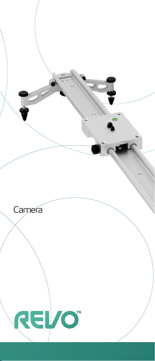
Camera
Track Slider
With Adjustable Feet
Page 2
Congratulations on your purchase of the Revo
Camera Track Slider.
Revo’s camera track slider is a sturdy, portable, and
lightweight mini dolly that adds production value to any
video shoot. It provides the ability to get quick, smooth
short-run dolly shots and a variety of tracking shots without
having to carry a full dolly system and track.
The heavy-duty aluminum construction with
precision-engineered rails provide smooth and quiet
panning for the entire length of the rails and ensure
effortless motion for a rig of up to 21 pounds. Individually
adjustable feet and an integrated bull’s-eye bubble level
make leveling the rail easy and ensure that it won’t wobble
if placed on a slightly uneven surface. Threaded mounts
(3/8” and 1/4”-20) on the mounting plate assure
compatibility with most cameras or tripod heads.
The camera track slider is easily assembled without tools.
One or two sets of threaded 1/4”-20 and 3/8” holes on the
rail provide the option of mounting the slider on top of a
single tripod (RS-600AF), or between two tripods
(RS-850AF and RS-1200AF).
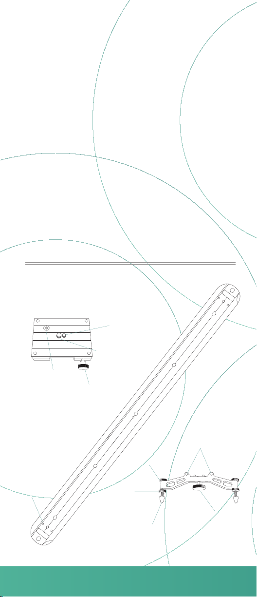
Components
Camera mount platform
Camera sliding rail
Bubble
level
1/4”-20
threaded
holes (for
adjustable
feet)
1/4”-20 mounting
screw
3/8” mounting
screw
Tension
control knob
Locking
nut
Height
adjustment
knob
Leg with
adjustable
feet
2× Adjustable feet
Rubber
pads
Thumb
screw
Page 3

Instructions
Attaching a camera or tripod head to the camera
mount
Remove the camera mount from the sliding rail by
1
sliding the camera mount off of the rail. This may
require removing either of the adjustable feet.
Unscrew the mounting screw that will not be used
2
from the camera mount and set it aside.
Use the 3/8” or 1/4”-20 mounting screw to attach a
3
camera or tripod head to the mounting plate.
1/4”-20 screw3/8” screw
Note: the mounting screw may need to be tightened with
an Allen key (not included.)
Attaching the legs and adjusting the feet
Align the two posts on the leg with the guide holes on
1
the rail. Make sure the rubber pads on the frame are
facing in toward the center of the rail.
Rubber Pads
Tighten the thumb screw until tight and the leg is
2
secure.
Once one leg has been attached, slide the camera
3
mounting plate with the tripod head/camera onto the
rail.
Attach the second leg.
4
Refer to the bubble level on the camera mounting
5
plate to determine if it is level. Also check to see if the
assembled track slider wobbles.
Loosen the locking nuts on all of the feet.
6
Page 4

Adjust the height of each foot until the bubble in the
7
bubble level is within the bull’s-eye, or until all feet rest
uniformly on the surface without wobbling.
B
A
Tighten the locking nuts by tightening them against
8
the frame of the leg.
Tripod attachment
The rail has 3/8” and 1/4”-20 threaded holes for attaching
to one or two tripods.
The RS-600AF is designed to be attached to a single
tripod, and the threaded holes are located in the center of
the rail.
The RS-850AF and the RS-1200AF are designed to
attach to two tripods, and the threaded holes are located
at either end of the rail.
To attach the rail to one or two tripods, do the following:
Remove one of the adjustable feet and the camera
1
mounting plate from the rail.
(RS-600AF) Screw the threaded mount of the tripod
2
into the threaded hole of the rail.
(RS-850AF and RS-1200AF) After attaching one end
3
of the rail to the first tripod, slide the camera mounting
plate onto the rail from the other end, and then attach
the second tripod to the other side of the rail.
Reattach the feet so that feet are in place at both ends
4
of the rail and prevent the camera from sliding off.
Page 5

Adjusting the tension of the camera mounting
plate
To adjust the tension, do the following:
To add tension, turn the tension control knob
1
clockwise.
For less tension, turn the tension control knob counter
2
clockwise.
Specifications
RS-600AF
Load capacity: 21 lbs. (1 0 kg)
Dimensions: 3.5˝ × 2.75˝ × 23.6˝ (9 × 7 × 60 cm)
Weight: 1.86 lbs. (847 g)
Height adjustment: 0.5˝ (1 cm)
RS-850AF
Load capacity: 15.4 lbs. (7 kg)
Dimensions: 3.5˝ × 2.75˝ × 33.5˝ (9 × 7 × 84.3 cm)
Weight: 2.5 lbs. (1.13 kg)
Height adjustment: 0.5˝ (1 cm)
RS-1200AF
Load capacity: 11 lbs. (5 kg)
Dimensions: 3.5˝ × 2.75˝ × 47.2˝ (9 × 7 × 120 cm)
Weight: 3.18 lbs. (1.44 kg)
Height adjustment: 0.5˝ (1 cm)
Visit revocinegear.com for more information on
our complete line of video mounting products.
Page 6

Warnings
Please read and follow these instructions, and keep this
manual in a safe place.
Handle the unit with care.
Camera sliding rail may have sharp edges
Clean the unit with a soft, dry cloth.
Use only parts provided by the manufacturer.
Make sure everything is secure before proceeding.
Make sure the item is intact and that there are no
missing parts.
Do not exceed the maximum load capacity.
All photos are for illustrative purposes only.
One-Year Limited Warranty
This REVO product is warranted to the original purchaser to be
free from defects in materials and workmanship under normal
consumer use for a period of one (1) year from the original
purchase date or thirty (30) days after replacement, whichever
occurs later. The warranty provider’s responsibility with respect to
this limited warranty shall be limited solely to repair or replacement, at the provider’s discretion, of any product that fails during
normal use of this product in its intended manner and in its
intended environment. Inoperability of the product or part(s) shall
be determined by the warranty provider. If the product has been
discontinued, the warranty provider reserves the right to replace it
with a model of equivalent quality and function.
This warranty does not cover damage or defect caused by misuse,
neglect, accident, alteration, abuse, improper installation or
maintenance. EXCEPT AS PROVIDED HEREIN, THE WARRANTY PROVIDER MAKES NEITHER ANY EXPRESS WARRANTIES
NOR ANY IMPLIED WARRANTIES, INCLUDING BUT NOT
LIMITED TO ANY IMPLIED WARRANTY OF MERCHANTABILITY OR FITNESS FOR A PARTICULAR PURPOSE. This warranty
provides you with specific legal rights, and you may also have
additional rights that vary from state to state.
To obtain warranty coverage, contact the Revo Customer Service
Department to obtain a return merchandise authorization
(“RMA”) number, and return the defective product to Revo along
with the RMA number and proof of purchase. Shipment of the
defective product is at the purchaser’s own risk and expense.
For more information or to arrange service, visit www.revocinegear.com
or call Customer Service at 212-594-2353.
Product warranty provided by the Gradus Group.
www.gradusgroup.com
TM
REVO
A Gradus Group Brand
REVO is a registered trademark of the Gradus Group.
© 2015 Gradus Group LLC. All Rights Reserved.
GG1
 Loading...