

Page 1
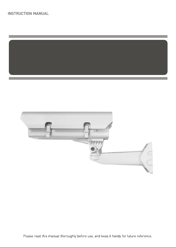
540TV Lines Super
High Resolution Color Camera
Page 2

Page 3
- ii -
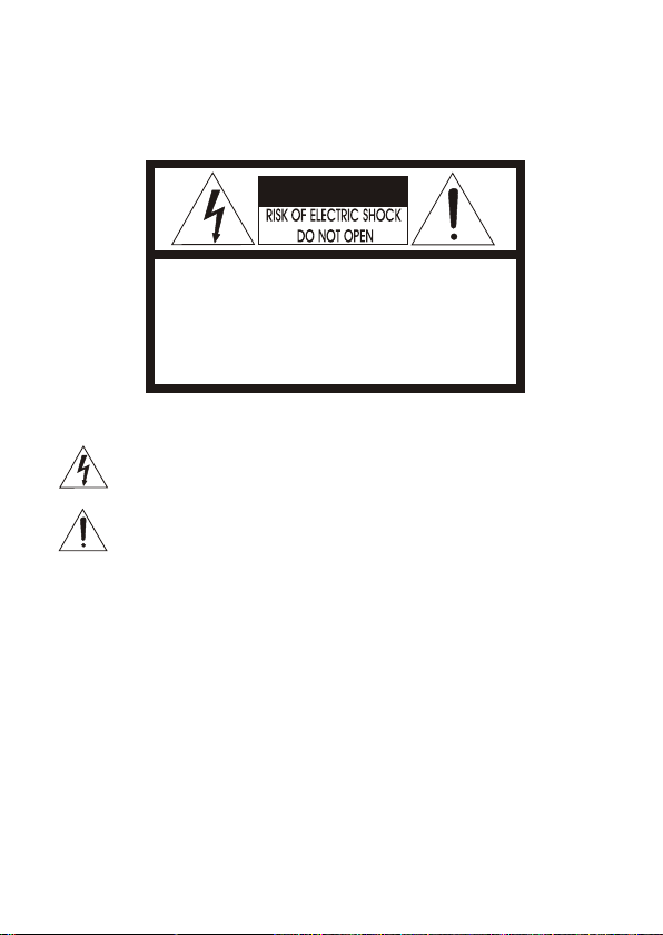
WARNINGS:
CAUTION:
CAUTIONCAUTION
CAUTION: TO REDUCE THE RISK OF ELECTRIC SHOCK,
DO NOT REMOVE COVER(OR BACK).
NO USER-SERVICEABLE PARTS INSIDE.
REFER SERVICING TO QUALIFIED SERVICE PERSONNEL.
EXPLANATION OF GRAPHICAL SYMBOLS
The lightning flash with arrowhead symbol, within an equilateral triangle, is
intended to alert the user to the presence of uninsulated "dangerous voltage"
within the product's enclosure that may be of sufficient magnitude to constitute a
risk of electric shock to persons.
The exclamation point within an equilateral triangle is intended to alert the user to
the presence of important operating and maintenance (servicing) instructions in the
literature accompanying the product.
Should any liquid or solid object fall into the cabinet,
unplug the unit and have it checked by the qualified
personnel before operating it any further.
Unplug the unit from the wall oulet if it is not going to
be used for several days or more. To disconnect the
cord, pull it out by the plug. Never pull the cord itself.
Allow adequate air circulation to prevent internal heat
build-up. Do not place the unit on surfaces (rugs,
blankets, etc.) or near materials(curtains, draperies)
that may block the ventilation holes.
Height and vertical linearity controls located at the
rear panel are for special adjustments by qualified
personnel only.
Do not install the unit in an extremely hot or
humid place or in a place subject to excessive
dust, mechanical vibration.
The unit is not designed to be waterproof.
Exposure to rain or water may damage the unit.
Clean the unit with a slightly damp soft cloth.
Use a mild household detergent. Never use
strong solvents such as thinner or benzine as
they might damage the finish of the unit.
Retain the original carton and packing
materials for safe transport of this unit in the
future.
Safety ----------------------------------------- Installation -----------------------------------
Cleaning --------------------------------------
PRECAUTIONS
TO REDUCE THE RISK OF FIRE OR ELECTRIC SHOCK, DO NOT EXPOSE THIS PRODUCT TO RAIN OR
MOISTURE. DO NOT INSERT ANY METALLIC OBJECTS THROUGH THE VENTILATION GRILLS OR
OTHER OPENINGS ON THE EQUIPMENT.
Page 4
- iii -
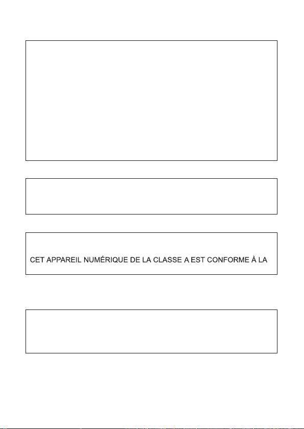
FCC INFORMATION : THIS EQUIPMENT HAS BEEN TESTED
AND FOUND TO COMPLY WITH THE LIMITS FOR A CLASS A DIGITAL
DEVICE, PURSUANT TO PART 15 OF THE FCC RULES. THESE
LIMITS ARE DESIGNED TO PROVIDE REASONABLE PROTECTION
AGAINST HARMFUL INTERFERENCE WHEN THE EQUIPMENT IS
OPERATED IN A COMMERCIAL ENVIRONMENT. THIS EQUIPMENT
GENERATES, USES, AND CAN RADIATE RADIO FREQUENCY
ENERGY AND IF NOT INSTALLED AND USED IN ACCORDANCE WITH
THE INSTRUCTION MANUAL, MAY CAUSE HARMFUL INTERFERENCE
TO RADIO COMMUNICATIONS. OPERATION OF THIS EQUIPMENT IN
A RESIDENTIAL AREA IS LIKELY TO CAUSE HARMFUL
INTERFERENCE IN WHICH CASE THE USER WILL BE REQUIRED TO
CORRECT THE INTERFERENCE AT HIS OWN EXPENSE.
CAUTION : CHANGES OR MODIFICATIONS NOT EXPRESSLY
APPROVED BY THE PARTY RESPONSIBLE FOR COMPLIANCE
COULD VOID THE USER'S AUTHORITY TO OPERATE THE EQUIPMENT.
THIS CLASS A DIGITAL APPARATUS COMPLIES WITH CANADIAN
ICES-003.
NORME NMB-003 DU CANADA.
WARNING
THIS IS A CLASS A PRODUCT. IN A DOMESTIC ENVIRONMENT THIS
PRODUCT MAY CAUSE RADIO INTERFERENCE IN WHICH CASE
THE USER MAY BE REQUIRED TO TAKE ADEQUATE MEASURES.
CE COMPLIANCE STATEMENT
FCC COMPLIANCE STATEMENT
Page 5

- iv -
IMPORTANT SAFEGUARDS
1. Read t hes e i ns t ructions .
2. Keep t hes e i ns t ructions .
3. Heed a ll wa rni ngs .
4 . Foll ow al l i nstructions .
5. Do n ot us e t his a ppa rat us ne ar wa ter.
6. Clea n o nly w it h d ry cloth.
7. Do n ot bl ock a ny ve ntilatio n o pen in g s. Install i n a cco rda nce w ith t he
man ufa cturer's inst ruc tio ns.
8. Do n ot in sta ll n e ar any heat so urc es su ch as r adi ators, h eat r egi ste rs,
sto ves , or other a ppa rat us (i ncluding ampl ifi ers ) tha t produce heat.
9. Do n ot de fea t the s afety purp ose o f t he po larized or g rou ndi ng- typ e
plu g. A pola riz ed pl ug ha s two blad es wi th on e wid er than the other.
A gro und ing type p lug h as tw o bla des a nd a th ird g rou ndi ng prong.
The w ide blad e o r the t hird prong are pr ovi ded f or yo ur safety. If the
pro vid ed plug does not fi t i nto y our outl et, c ons ult a n electrician f or
rep lac ement of t he ob sol ete o utlet.
10.Pro tec t t he po wer c ord f rom b ein g wal ked o n o r pin ch e d particul arl y
at pl ugs , convenience r ece pta cle s, and the p oin t w here they exit fr om
the a ppa ratus.
11. On ly use attachme nts /ac ces sories s pec ifi ed by t he manufactur er.
12. U se on ly wi th th e cart, stan d, tr ipo d, br ack et, or t abl e spe cified b y t he
man ufa cturer, o r s old w ith the ap par atu s. Wh en a cart is u sed , u se
cau tio n when moving t he ca rt/ apparatus c omb ina tion to avoid i nju ry
fro m tip -over.
13. U npl ug th is a p paratus du rin g l igh tning stor ms or w hen u nus ed fo r
lon g per iods of time.
14. R efe r a ll servici ng to q ual ifi ed s e rvice pers onn el. S erv ici ng is
req uir ed when the appar atu s h as been damaged i n a ny wa y, s uch as
pow er- supply c ord o r p lug is d ama ged , liquid h as be en mo ist ure, does
not o per ate norm all y, o r h as been dropped .
15. C AUT ION T HES E SERVICIN G I NST RUC TIONS AR E F OR US E BY
QUA LIF IED SERV ICE P ERS ONN EL ONLY. TO REDUCE THE R ISK
OF EL ECT RIC SHOC K D O NOT P ERFORM AN Y SERVICING OTHE R
THA N THAT C ONTAINE D I N THE O PERATIN G INSTRUCTION S
UNL ESS Y OU QR E QUA LI F IED TO DO S O.
16. U se Ce rti fie d/Listed C las s 2 p owe r source o nly.
Page 6

TABLE OF CONTENTS
- v -
INTRODUCTION 1
CONTENTS OF PACKAGE 2
CAMERA CONNECTIONS 3
WALL BRACKET MOUNTING 4
CAMERA OVERVIEW 5
WIRING DIAGRAM 6
HOUSING KIT SPECIFICATIONS 7
SPECIFICATIONS 8
CONNECTIONS 6
Page 7

INTRODUCTION
- 1 -
The camera provides high-quality images using SONY CCD technology especially designed
for closed-circuit television (CCTV) and security
surveillance applications.
Features:
High resolution and high performance 1/3" SONY Super HAD CCD technology
Excellent picture quality
540 lines(Color) of resolution
0.25 Lux(Color) / 0.01 Lux(B/W) @ F1.2 Sensitivity (True D&N)
0.25 Lux(Color) @ F1.2 Sensitivity (Digital D/N)
C/CS, backfocus cam for easy adjustment
Auto electronic shutter [1/60(1/50) ~ 1/100,000] and manual electronic Shutter modes
Auto Trace White balance modes
Selectable BLC function
Day & Night (True D&N / Digital D/N)
AGC (Auto Gain Control)
Video out(BNC)
with 4-pin connector
Operates in 12VDC or 24VAC
Use Certified / Listed Class 2 power supply only.
Quick connect for video or DC lens
IMPORTANT : The user of this camera is responsible for checking and
complying with local, state, and federal laws and statutes concerning the
recording and monitoring of audio signals.
Page 8

Installation of the camera must be performed by qualified service personnel in accordance
with all local and national electrical and mechanical codes.
Carefully remove the color camera and its accessories from the carton
and verify that they were not damaged in shipment.
The contents of the package includes:
1. CAMERA HOUSING KIT
2. This manual
3. L-wrench (5mm) --------------- 1ea
(2.5mm) ------------- 1ea
4. ANCHOR (5mm) --------------- 4ea
CONTENTS OF PACKAGE
- 2 -
Page 9

- 3 -
CAMERA CONNECTIONS
2
1
REMINDER:
Never aim the
camera directly
into the sun.
1. Color Lead Wire & Color Display Label
2. Video : BNC connector used to connect the camera to a monitor, switcher, etc.
COLOR
BLACK
RED
DESCRIPTION
AC24V
AC24V
COLOR
BLACK
WHITE
DESCRIPTION
DC12V
DC12V
Page 10

1. Use fasteners of appropriate size and type to attach the bracket to the wall surface.
Position the housing so that it allow for viewing of the selected area.
2. Adjust the movable arm of the wall bracket to attain the desired position.
One it is in place,tighten the bolt located at the pivot point of the movable arm.
3. If you want to pull out the relevant cable, remove the knockout on the
wall bracket mounting.
1
2
3
WALL BRACKET MOUNTING
- 4 -
Page 11

- 5 -
CAMERA OVERVIEW
REAR VIEW
2
3
4
5
1
AUTO
COLOR
D/N
1
2
3
4
5
IRIS LEVEL
POWER INPUT TERMINAL
VIDEO OUTPUT CONNECTOR
POWER INDICATOR
FUNCTION SWITCH
DC 12V
~ AC 24V ~
1) IRIS LEVEL
2) FUNCTION SWITCH
Adjust the DC-type auto iris lens for an optimum picture using this volume.
- E/I (on/off)
When set to the ON position, the electronic iris switch automatically varies the camera's shutter
to mimic auto-iris control, allowing fixed or manual iris lenses to be used in a wider range.
When this switch is set to ON, turn the F/F switch OFF.
- FF (on/off)
This function is used for removing flicker, when camera signal format does not coincide with
power source frequency being used.
- BLC (on/off)
This on/off switch controls backlight compensation. When set to ON, the camera will
automatically try to maintain proper exposure in the specific area even if the lighting level changes.
- AGC (on/off)
The auto gain control switch allows the video signals to maintain a constant level. This switch is
useful when using the camera at low-light levels and when lighting levels change over time.
For best low light conditions, this switch should set to ON.
- Day/Night (Auto/Color)
Use this switch to set the camera Day/Night mode Auto(ON) or Color(OFF)
Auto : D/N mode converse automatically (AGC must set to ON)
Color : Only Color
- A/I (DC/VIDEO)
Use this switch to set the auto iris type.
3) POWER INPUT TERMINAL
4) POWER INDICATOR
5) VIDEO OUTPUT CONNECTOR
Page 12

- 6 -
CONNECTIONS
1) POWER INPUT TERMINAL
This terminal accepts a DC12V or AC24V power
source from a DC12V or AC24V +/-10% 60/50Hz +/- 1Hz
Use Certified / Listed Class 2 power supply only.
In DC power, use the Adapter mode than DC 12V 500mA Capacity.
CLASS 2
+ DC 12V -
~AC 24V~
2) VIDEO OUT CONNECTOR
BNC : This BNC connector provides a 1.0Vp-p/75 ohms composite video Signal.
WIRING DIAGRAM
24Vac Out
to Heater
24Vac Power
Supply Output
24Vdc Out
to Blower
24Vac Power
Supply Input
Ground
Ground
(B+)
(Ground)
J3
J6
J4 J5
J1
24 Vac
* HEATER AND BLOWER
Page 13

- 7 -
HOUSING KIT SPECIFICATIONS
5.5(14)
2.5(6.4)
2.3(5.9)
20.5(52.02)
9.68(24.6)
Unit: inch(cm)
Camera Housing Window Size 2.5" W x 2.3" H (6.4cm x 5.9cm)
Camera Housing Construction Die-cast, extruded, and sheet aluminum
Camera Housing Finish
Light-gray ployester powder coat
Wall Bracket Pan Adjustment 360
Wall Bracket Tilt Adjustment
70
Wall Bracket Locking Method
4 holes for fasteners of a suitable size & type.
Mount to a secure solid surface.
Total Dimension(WxHxL)
5.5" W x 9.68" H x 20.5" D
(14cm x 24.6cm x 52.02cm)
Total Weight
9.15Ib( 4.15kg)
Page 14

Power source
Power consumption
Image sensor
Total pixels
Scanning sys tem
Scanning fre quency
Sync. sys t em
Electronic s hutter
Resolution
Min. illumination
Video output
2:1 interlace
NTSC : 15.734KHz(H) x 59.94Hz(V) / PAL : 15.625KHz(H) x 50Hz(V)
NTSC : 1/60 ~ 1/100,000 sec. / PAL : 1/50 ~ 1/100,000 sec.
540 TV Lines
Color ( 0.25 Lux) / BW(0.01Lux)
@ F1.2, 50 IRE
1.0 Vp-p (75ohm, composite)
More than 50dB (AGC OFF)
ON / OFF
ON / OFF
Auto / Color Fix
DC / VIDEO
ATW Fixed
NTSC : 811(H) x 508(V) / PAL : 7 95(H) x 596(V)
MODEL
S/N ratio
BLC
AGC
Day/Night
Auto iris lens
White Balance
F
U
N
C
T
I
O
N
SPECIFICATIONS
General
Power
Power input
Lens mount
1/4''-20 UNC (top or bottom)
2-Pin Terminal block
4-Pin mini din jack (standard connection)
C/CS mount (Selected through back focus)
Mounting hol e
Connector
&
etc.
Video output
Auto iris output
Operating te mperature
Operating hu midity
BNC connector
0 ~ 96% (non-condensing)
DC 12V / AC 24V 10%
5.2 Watts
Internal
Dip switch
Camera Control
ON / OFF
ON / OFF
E/I
Flickerless
+50
True D&N
(NTSC) (PAL)
Digital D/N
(NTSC) (PAL)
4.0 Watts
Color ( 0.25 Lux)
@ F1.2, 50 IRE
Blower
Heater
Power Supply
Power Consumpti on
Blower ON
Blower OFF
Power Supply
Power Consumpti on
Heater ON
Heater OFF
24 Vac
3.4W
t C > 35 C +/-3 C
T F > 95 F +/-5 F
t C < 20 C +/-3 C
24 Vac
20W
t C < 5 C +/- 3 C
T F < 41 F +/- 5 F
t C > 15 C +/- 3 C
- 8 -
Page 15

Page 16

50302785B
540TV Lines Super High Resolution Color Camera
 Loading...