

Page 1
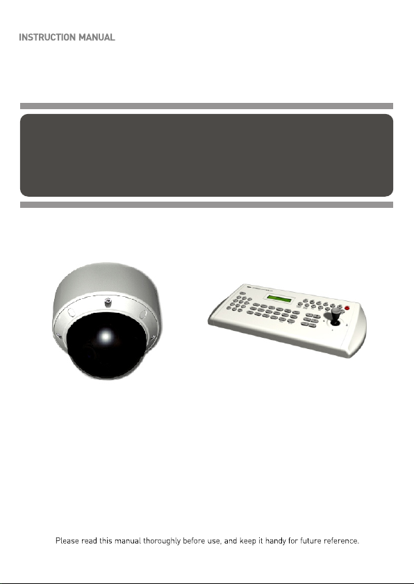
MINITRAX Dome Camera
PTZ VANDAL RESISTANT
COLOR DOME CAMERA
Keyboard Controller
(not supplied)
Surface mount
Page 2
ii
WARNINGS AND CAUTIONS:
CAUTION:
CAUTIONCAUTION
CAUTION: TO REDUCE THE RISK OF ELECTRIC SHOCK,
DO NOT REMOVE COVER(OR BACK).
NO USER-SERVICEABLE PARTS INSIDE.
REFER SERVICING TO QUALIFIED SERVICE PERSONNEL.
EXPLANATION OF GRAPHICAL SYMBOLS
The lightning flash with arrowhead symbol, within an equilateral triangle, is
intended to alert the user to the presence of uninsulated "dangerous
voltage" within the product's enclosure that may be of sufficient magnitude
to constitute a risk of electric shock to persons.
The exclamation point within an equilateral triangle is intended to alert the
user to the presence of important operating and maintenance (servicing)
instructions in the literature accompanying the product.
Should any liquid or solid object fall into the cabinet,
unplug the unit and have it checked by the qualified
personnel before operating it any further.
Unplug the unit from the wall oulet if it is not going to
be used for several days or more. To disconnect the
cord, pull it out by the plug. Never pull the cord itself.
Allow adequate air circulation to prevent internal
heat build-up. Do not place the unit on surfaces
(rugs, blankets, etc.) or near materials(curtains,
draperies) that may block the ventilation holes.
may block the ventilation holes.
Height and vertical linearity controls located at the
rear panel are for special adjustments by qualified
personnel only.
Do not install the unit in an extremely hot or humid
place or in a place subject to excessive dust,
mechanical vibration.
The unit is not designed to be waterproof.
Exposure to rain or water may damage the unit.
Clean the unit with a slightly damp soft cloth.
Use a mild household detergent. Never use strong
solvents such as thinner or benzine as they might
damage the finish of the unit.
Retain the original carton and packing materials for
safe transport of this unit in the future.
Safety ----------------------------------------- Installation -----------------------------------
Cleaning --------------------------------------
PRECAUTIONS
TO REDUCE THE RISK OF FIRE OR ELECTRIC SHOCK, DO NOT EXPOSE THIS
PRODUCT TO RAIN OR MOISTURE. DO NOT INSERT ANY METALLIC OBJECTS
THROUGH THE VENTILATION GRILLS OR OTHER OPENINGS ON THE EQUIPMENT.
Page 3
FCC COMPLIANCE STATEMENT
FCC INFORMATION : THIS EQUIPMENT HAS BEEN TESTED AND
FOUND TO COMPLY WITH THE LIMITS FOR A CLASS A DIGITAL DEVICE,
PURSUANT TO PART 15 OF THE FCC RULES. THESE LIMITS ARE
DESIGNED TO PROVIDE REASONABLE PROTECTION AGAINST HARMFUL
INTERFERENCE WHEN THE EQUIPMENT IS OPERATED IN A
COMMERCIAL ENVIRONMENT. THIS EQUIPMENT GENERATES, USES,
AND CAN RADIATE RADIO FREQUENCY ENERGY AND IF NOT INSTALLED
AND USED IN ACCORDANCE WITH THE INSTRUCTION MANUAL, MAY
CAUSE HARMFUL INTERFERENCE TO RADIO COMMUNICATIONS.
OPERATION OF THIS EQUIPMENT IN A RESIDENTIAL AREA IS LIKELY TO
CAUSE HARMFUL INTERFERENCE IN WHICH CASE THE USER WILL BE
REQUIRED TO CORRECT THE INTERFERENCE AT HIS OWN EXPENSE.
CAUTION : CHANGES OR MODIFICATIONS NOT EXPRESSLY
APPROVED BY THE PARTY RESPONSIBLE FOR COMPLIANCE COULD
VOID THE USER'S AUTHORITY TO OPERATE THE EQUIPMENT.
THIS CLASS A DIGITAL APPARATUS COMPLIES WITH CANADIAN ICES-003.
NORME NMB-003 DU CANADA.
WARNING
THI S IS A CLASS A PROD UCT. IN A DOME STI C ENV IRO NME NT THI S
PRO DUC T MAY CAUS E RAD IO IN TER FER ENC E IN WH ICH C AS E T HE
US ER MAY B E R EQ UI RED T O TAKE A DE QU ATE M EAS URE S.
CE COMPLIANCE STATEMENT
iii
Page 4

1. Read these instructions.
2. Keep these instructions.
3. Heed all warnings.
4. Follow all instructions.
5. Do not use this apparatus near water.
6. Clean only with dry cloth.
7. Do not block any ventilation openings. Install in accordance with the
manufacturer's instructions.
8. Do not install near any heat sources such as radiators, heat
registers, stoves, or other apparatus (including amplifiers) that
product heat..
9. Do not defeat the safety purpose of the polarized or grounding-type
plug. A polarized plug has two blades with one wider than the other.
A grounding type plug has two blades and a third grounding prong.
The wide blade or the third prong are provided for your safety. If the
provided plug does not fit into your outlet, consult an electrician for
replacement of the obsolete outlet.
10. Protect the power cord from being walked on or pinched
particularly at plugs, convenience receptacles, and the point where
exit from the apparatus.
11. Only use attachments/accessories specified by the manufacturer.
12. Unplug this apparatus during lightning storms or when unused for
long periods of time.
13. Refer all servicing to qualified service personnel. Servicing is
required when the apparatus has been damaged in any way, such
as power-supply cord or plug is damaged, liquid has been spilled or
objects have fallen into the apparatus, the apparatus has been
exposed to rain or moisture, does not operate normally, or has been
dropped.
14. CAUTION - THESE SERVICING INSTRUCTIONS ARE FOR USE
BY QUALIFIED SERVICE PERSONNEL ONLY. TO REDUCE THE
RISK OF ELECTRIC SHOCK DO NOT PERFORM ANY
SERVICING OTHER THAN THAT CONTAINED IN THE
OPERATING INSTRUCTIONS UNLESS YOU ARE QUALIFIED TO
DO SO.
15. Use Certified/Listed Class 2 power supply transformer only.
thy
IMPORTANT SAFEGUARDS
iv
Page 5

TABLE OF CONTENTS
Chapter 1. INTRODUCTION
1.1 Features 1
1.2
Chapter 2. INSTALLATION AND CONFIGURATION
2.1 Package Contents 3
2.2 Base Installation 3
2.3 Heater kit Installation (option) 6
2.4 Basic Configuration PTZ Dome Camera System 7
2.5 Setting Dome Camera Termination 8
2.6 Setting Protocol of Dome Camera 9
2.7 Setting Address (ID) of Dome Camera 10
2.8 Connecting Wiring 11
Chapter 3. PROGRAM AND OPERATION
3.1 Main Menu 12
3.2 Preset Menu 13
3.3 Tour Menu 15
3.4 Auto Scan Menu 16
3.5 Alarm Menu 17
3.6 Camera Setup Menu 18
3.7 Dome Setup Menu 23
Chapter 4. TROUBLESHOOTING AND MAINTENANCE
4.1 Troubleshooting 26
4.2 Preventive Maintenance 27
Chapter 5. SPECIFICATIONS
5.1 General Specifications 28
5.2 Dimensions 30
APPENDIX. PELCO PROTOCOL FUNCTION TEST 30
Operation Requirements 2
V
Page 6

Chapter 1.
Introduction
1.1 Features
The PTZ Dome keyboard controller and the PTZ Dome camera make up
the building blocks for any surveillance/security system. Using multiple
keyboard controllers and multiple dome cameras, no place is too large
for monitoring. Extensible and flexible architecture facilitates remote
control functions for a variety of external switching devices such as
multiplexers and DVRs.
60 Preset positions.
4 Tours consist of Preset
4 Auto Scans
Home Function: camera automatically goes to preset, tour, auto
scan after the controller has been idle for an amount of time.
1 Alarm input (OFF / NC / NO) and 2 Alarm states (momentary,
timeout).
Programmable user preferences (alarm, preset, title, etc.).
Up to 63 selectable camera addresses.
Built-in RS-485 receiver driver.
Clear bubble with black liner (shelter) for concealing the camera.
Optional tinted bubble, wall mount.
24VAC or 12VDC
If use 12VDC power adapter, use Certified/Listed Class 2 power
supply transformer only
Use Certified/Listed Class 2 power transformer only.
1
Page 7
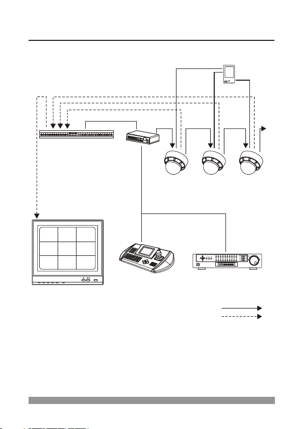
1.2 Operation Requirements
Typical System Configuration
Alarm Input
<Sensor>
J-box
PTZ DOME PTZ DOME PTZ DOME
MULTIPLEXER
MONITOR
KEYBOARD DVR
RS-485
RS-485
RS-485
VIDEO
2
Page 8

Chapter 2.
Installation and Configuration
2.1 Package Contents
The package contains the following.
PTZ Dome (Dome camera) 1
Instruction manual (This document) 1
RS-485, ALARM IN, POWER IN connector 1
Accessory kit for installing PTZ Dome 1
Template sheet 1
Safety wire 1
2.2 Base Installation
VIDEO OUT
RS-485 (2P-connector (Black))
To RS-485 connecting unit
To SENSOR
ALARM IN (2P-connector (Blue))
POWER IN (3P-connector (Red))
AC 24V/DC 12V
COMPOSITE CABLE
Note: When wiring, note the following:
For the RS-485, ALARM IN cable, insulate the bare conductor part not to be
exposed after wiring.
For the video cable, keep the BNC connector (metal part) away from any other
metal material.
Connection Cable Description
COLOR
BLACK
BROWN
RED
ORANGE
BLUE
VIOLET
DESCRIPTION
485 (+)
485 ( )
AC24V / DC12V
AC24V / DC12V
ALARM COMMON
ALARM IN
-
3
Page 9
2.2 Base Installation, continued
4
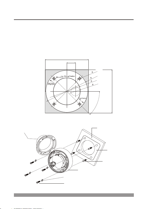
1. Make mounting holes and cable hole in the place (ceiling) to which this dome
camera is installed using the supplied template sheet.
Warning: The total mass of the main unit is approx 1.3kg. Check whether the
ceiling to which the Dome Camera is installed is strong enough to hold the unit
mass. If not, the Dome Camera could fall, causing injury.
Mounting Screw
M6x35 (4x)
Plastic Anchor (4x)
CEILING
Rubber
Washers(4x)
Template Sheet
Dome Cover
Dome Base
[Installation]
TEMPLATE SHEET
145.0
29.0
-
5
7
t
n
l
4
m
o
n
e
.
(
i
g
h
o
)
u
1
4
0
0
.
9
0
.0
(c
a
b
le
ho
le
)
3
0
.0
145.0
o
4
5
4
Page 10
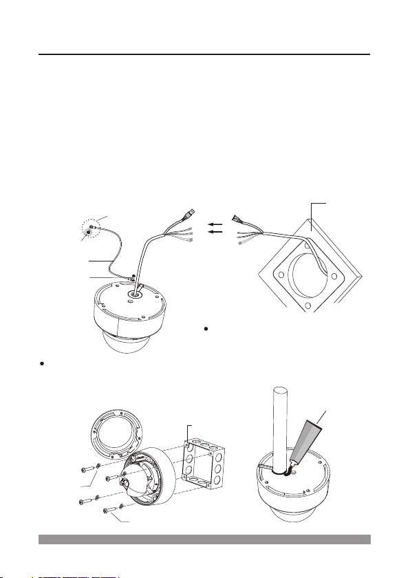
2.2 Base Installation, continued
2. Extract each wire through the cable hole and wire the supplied power,
RS-485 and alarm-in connecter .
3. Attach the safety wire for securing the dome camera to ceiling or structure
not to fall.
4. Unlock 4 torx screws on the dome cover and lock the dome base firmly with
supplied 4 fixing screws.
Warning: Fasten the fixing screws of the dome camera firmly, or the dome
camera could fall, causing injury.
5. Lock the housing cover with 4 torx screws.
CEILING
The housing can also be mounted
on a 4s or 2s electrical box.
WHEN MOUNTING HOUSING TO
THE ELECTRICAL BOX
ELECTRICAL
BOX
Torx screws
UNC 8-32 x 0.75
Rubber
Washers(4x)
WHEN USING PIPE OR PLUG
If you want to use a pipe or plug, you
should remove the hole grommet
outside and seal using sealant
(not supplied) not to be intruded water.
SILICON SEALANT
(not supplied)
Safety wire
M3x5 screw
To structure
(not supplied)
5
Page 11
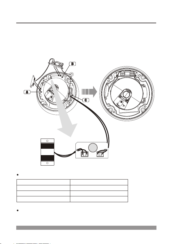
2.3 Heater kit Installation (option)
HEATER (IF APPLICABLE)
Use Certified/Listed Class 2 power supply transformer only.
POWER
Power Supply
Power Consumption
Heater ON
Heater OFF
24VAC / 12VDC
20W / 10W (heater on)
o o
at 41 F (5 C)
o o
at 59 F (15 C)
Heate r
J3
J1
SW1
1. Place the Heater element in slot "A". Please ensure that the cables
are facing upwards and the heater is pointing towards the Dome.
2. Place the PCB in slot "B". Please ensure that the PCB is facing away
from the Dome with the connection blocks at the top.
3. Place the plug in the Socket "C" (J701) which is found on the main
PTZ board.
6
Page 12

2.4 Basic Configuration PTZ Dome Camera System
Alarm Input
<Sensor>
PTZ DOME
MONITOR
ALARM/PCALARM/PC DVRDVRMUXMUX
RS-232CRS-232C
--
DOME1DOME1
++
DATA2DATA2
SLAVE KBDSLAVE KBD
DOME2DOME2
GG
VIDEOVIDEO
DATA1DATA1
DC 12VDC 12V
ININ
GG--++ ++ -- GG
DATA1
DATA2 DATA1
J-BOX BACK
J-BOX FRONT
REAR
REAR
DATA2
OR
KEYBOARD
KEYBOARD
7
Page 13

The device which is connected at end of line, whether it be a dome
camera or keyboard controller, must have the cable for communication
terminated by setting the appropriate DIP switch. Without proper
termination, there is potential for control signal errors. Total length of the
cable for communication should not exceed 1.2km.
2.5 Setting Dome Camera Termination
TERMINATION ON
Cable for communication
TERMINATION ON
Cable for communication
TERMINATION ON TERMINATION ON
INPUT
TERMINATION ON
OUTPUT
TERMINATION ON
1.2km 1.2km
REPEATER/SPLITTER
TERMINATION ON
TERMINATION ON
TERMINATION ON
TERMINATION ON
Cable for communication Cable for communication
DOME1 PORT DOME2 PORT
TERMINATION ON
TERMINATION ON
Cable for communication
DOME1 PORT
TERMINATION ON
Cable for communication
TERMINATION ON
TERMINATION ON
INPUT
TERMINATION ON
OUTPUT
TERMINATION ON
DOME2 PORT
Termination Diagram
RS-485 Termination S/W
Setting Unit for Termination
SW1
Terminated
Not terminated
1
ON
OFF
1
2
3
4
5
6
7
8
9
0
O
N
O
F
F
N
O
TOP
8
Page 14

2.6 Setting Protocol of Dome Camera
If a dome camera is to be installed with a PTZ Dome keyboard controller,
select F2 protocol. Consult service personnel if a dome camera is
installed with device other than a keyboard controller.
No. 9
ON OFF
OFF OFF
No. 10 Protocol
Fastrax-ll
Pelco - D
Figure 1 - Dome Camera Protocol Selection Switches
Dome Camera Function
S/W - No.
ON OFF FUNCTION
8
NTSC PAL NTSC/PAL
Dome Camera Protocol
Function
1
2
3
4
5
6
7
8
9
0
O
N
O
F
F
O
N
TOP
1
2
3
4
5
6
7
8
9
0
O
N
Dome Camera Function Selection Switches
9
Page 15

2.7 Setting Address (ID) of Dome Camera
To prevent wrong operation and malfunction, each dome camera must
have a unique address (ID).
When installing multiple dome cameras using a multiplexer, it is suggested
that the dome camera address match the multiplexer port number.
Example : Port 1 = Dome 1, Port 2 = Dome 2, .. Port 16 = Dome 16.
If more than 16 dome cameras are installed using two or more
multiplexers, ID of the dome camera should be ID of MUX x No.
of camera IN. (e.g. multiplexer ID= n, Camera IN= m then ID of
Dome =16x(n-1)+m )
Refer to Figures 1-2 for setting the
dome camera address (ID) and
protocol selection.
ID SETTING
ID Address
SW1
SW2 SW3 SW4 SW5 SW6
1
2
3
4
5
6
7
8
9
10
11
12
13
14
15
16
17
18
19
20
21
22
23
24
25
26
27
28
29
30
31
32
ON
OFF
ON
OFF
ON
ON
OFF
OFF
OFF
OFF
OFF
OFF
OFF
OFF
OFF
OFF
OFF
OFF
OFF
OFF ON OFF OFF OFF
OFF OFF OFF ON OFF OFF
ON
ON
OFF
OFF
ON
ON
OFF
OFF
ON
ON
ON
ON
ON
OFF
ON
OFF
ON
OFF
OFF
ON
OFF
ON
OFF
ON
OFF
OFF
OFF
OFF
OFF
OFF
OFF
OFF
OFF
OFF
OFF
OFF
OFF
OFF
OFF
OFF
OFF
OFF
ON
OFF
ON
OFF
ON
ON
ON
ON
ON
OFF OFF ON ON OFF OFF
OFF OFF OFF OFF ON OFF
OFF
OFF
OFF
ON
ON
ON
ON
ON
OFF
OFF
OFF
OFF
OFF
ON
ON
ON
ON
ON
OFF
OFF
OFF
OFF
OFF
ON
ON
ON
ON
ON
ON
ON
ON
ON
ON
ON
OFF
ON
OFF
ON
ON
OFF
ON
OFF
ON
ON
OFF
ON
OFF
ON
ON
OFF
OFF
ON
ON
ON
OFF
OFF
ON
ON
ON
OFF
OFF
ON
ON
OFF
ON
ON
ON
ON
OFF
ON
ON
ON
ON
OFF
ON
ON
ON
ON
OFF
OFF
OFF
OFF
OFF
OFF
OFF
OFF
OFF
OFF
OFF
OFF
OFF
OFF
OFF
ID Address
SW1
SW2 SW3 SW4 SW5 SW6
33
34
35
36
37
38
39
40
41
42
43
44
45
46
47
48
49
50
51
52
53
54
55
56
57
58
59
60
61
62
63
ON
OFF
ON
OFF
ON
ON
OFF
OFF
OFF
OFF
OFF
OFF
OFF
OFF
OFF
ON
ON
ON
OFF
OFF
OFF
OFFONOFF
OFFONOFF
OFFONON
ON
ON
OFF
OFF
ON
ON
OFF
OFF
ON
ON
ON
ON
ON
OFF
ON
OFF
ON
OFF
OFF
ON
OFF
ON
OFF
ON
OFF
OFF
OFF
OFF
OFF
OFF
ON
ON
ON
ON
ON
ON
OFF
OFF
OFF
OFF
OFF
OFF
OFF
OFF
OFF
OFF
ON
OFF
ON
OFF
ON
ON
OFF
OFF
ON
ON
OFF
ON
ON
ON
ON
ON
ON
ON
ON
ON
ON
ON
ON
OFF
OFF
OFF
OFF
OFF
ON
ON
ON
ON
ON
OFF
OFF
OFF
OFF
OFF
ON
ON
ON
ON
ON
ON
ON
ON
ON
ON
ON
OFF
ON
OFF
ON
ON
OFF
ON
OFF
ON
ON
OFF
ON
OFF
ON
ON
OFF
OFF
ON
ON
ON
OFF
OFF
ON
ON
ON
OFF
OFF
ON
ON
OFF
ON
ON
ON
OFF
ON
ON
ON
OFF
ON
ON
ON
ON
ON
ON
ON
ON
ON
ON
ON
ON
ON
ON
ON
ON
ON
ON
ON
ON
ON
ON
ON
Figure 2 - Setting Address(ID) of Dome Camera
OFF OFF OFF OFF O FF
ON
123456789
0
O
N
10
Page 16

2.8 Connecting Wiring
2.8-1 Connecting to the RS-485
The dome camera can be controlled remotely by an external device or
control system, such as a control keyboard, using RS-485 half-duplex.
Connect Marked Rx+, Rx- to Tx+ and Tx- of the RS-485 control system.
2.8-2 Connecting Video out connector (if RS-485 connecting)
Connect the video out(BNC) connector to the monitor or video input.
2.8-3 Connecting Alarms
You can use external devices to trigger the dome camera to go to the
preset position set in the alarm menu when an alarm occurs.
Alarm In / ALARM COMMON
Mechanical or electrical switches can be wired to the ALARM IN and
ALARM COMMON. The alarm input has a series resistor ( 1k ohm)
and the pull-up resistor (22k ohm) on 5VDC. The alarm common is the
ground level. The threshold voltage is 4.3V and should be stable for at
least 0.5 seconds to be detected.
See Chapter 3 Program and Operation for configuring alarm input.
Be careful when routing the cable from the camera to the alarm device. Try
not to put unnecessary strain on the cable or connectors. The cable can be
damaged if pulled by the connectors. Do not place the cable next to
fluorescent lights; interference may result. Do not use staples to support the
cable, as you may damage the cable. If the provided camera cable is not
long enough, do not substitute a telephone cable. Using a telephone cable
could damage the camera and/or alarm device. Alarm cable may be added
to the alarm device cable if it is not long enough. All connections should be
properly connected and insulated to prevent electrical shock and fire hazards.
CAUTION
11
Page 17

Notice
Below symbols mean some action of joystick controller.
/ : move joystick up and down direction.
/ : move joystick left and right direction.
: twist joystick.
: push defined key.
Chapter 3.
Program and Operation
3.1 Main Menu
KEY
MAIN MENU
PRESET
TOUR
AUTO SCAN
ALARM
CAMERA SETUP
DOME SETUP
EXIT
/ : move cursor up and down.
: select.
/ : move joystick left and right direction.
The MAIN MENU displays the available all functions of dome. You
should press key to display the MAIN MENU.
ESC
MENU
12
Page 18

3.2 Preset Menu
/ : move cursor up and down.
/ : move cursor left and right or select or change values.
: move dome camera to saved preset point at NUMBER:xx, or
without data saving.
character at
/ : exit current menu
ESC
If you need to view specific places routinely, you should program presets.
A preset is a programmed video scene with memorized pan, tilt and
zoom settings. Once programmed, selecting the preset number in your
Keyboard or DVR automatically calls up the preset. In addition, presets
may be assigned to the home function. The dome is capable of as many
as 60 presets when using an external keyboard.
PRESET MENU
NUMBER: 01
TITLE: ------------0/1234567890 1/1234567890
2/1234567890 3/1234567890
4/1234567890 5/1234567890
SAVE AND EXIT
EXIT
13
3.2-1 Set Presets using the MENU
1. Select the NUMBER: 01 using the Joystick.
2. Press CTRL button to move the position of the dome then the message
"CONTROL" displays on the screen.
3. Move the dome to the desired position using Joystick and set the zoom
level using the zoom in or zoom out buttons.
4. Release CTRL button then the message of "CONTROL" disappears on
the screen.
5. Select the SAVE AND EXIT to save the preset. Then the '=' mark
changes to the '* ' mark. To exit without saving, select the EXIT.
To insert title, move cursor to TITLE: and set proper title by Joystick.
Note: the ' = ' mark means a blank preset and the ' * ' mark means
a pre-defined preset position.
Page 19

3.2 Preset Menu, continued
3.2-3 Run Preset
Press preset number key and press PRST key. For example, if you
want to go to number 3 preset point. Press 3 key and press PRST key.
If you are in menu mode, twist the Joystick at the desired Preset Number.
But the cursor has to be placed at the NUMBER:.
3.2-2 Set Shortcut Preset
Press preset number key and press PGM and press PRST key. For
example, if you want to save to number 1 preset point, press 1 key and
press PGM key and press PRST key.
NOTE: You should save the preset number next to the last saved preset
number. If you save the preset to the random number not the number next to
the last saved preset number, that preset will not be saved.
14
Page 20

3.3 Tour Menu
/ : move cursor up and down.
/ : move cursor left and right or select or change values.
: change the character at TITLE : or charge preset number on
the - - mark.
/ : exit current menu without data saving.
ESC
3.3-1 Set Tours
Move cursor to TOUR : and set tour number by Joystick.
Move cursor to TITLE : and set proper title by Joystick.
Set dwell time at DWELL TIME :
Move cursor to - - and select proper preset number by Zoom In / Out.
Each point can be inserted progressively.
3.3-2 Run Tour
Press Tour number and press TOUR button. For example, you want to
run tour course 2, press 2 and press TOUR button.
TOUR MENU
TOUR : 1
TITLE: ------------DWELL TIME: 05 SEC
-- -- -- -- -- -- -- --
-- -- -- -- -- -- -- -DELETE DATA
SAVE AND EXIT
EXIT
15
Page 21

3.4 Auto Scan Menu
AUTO SCAN MENU
SCAN: 1
TITLE: -------------START POINT: 000.00
TILT AND ZOOM: 000.00
END POINT: 000.00
SAVE AND EXIT
EXIT
/ : move cursor up and down.
/ : move cursor left and right or select or change values.
: change the character at TITLE.
/ : exit current menu without data saving.
ESC
3.4-1 Set Auto Scans
Move cursor to TITLE: and set proper title by Zoom In / Out and Joystick.
Move cursor to START POINT: Move camera to desired starting Pan
point of auto scan range and set start point by pressing CTRL . (This will
initiate scan control.) Do not release CTRL button until the setting is not
completed.
Move cursor to TILT AND ZOOM: Move camera to desired Tilt point and
Zoom position by pressing CTRL button. Do not release CTRL button
until the setting is not completed.
Move cursor to END POINT: Move camera to desired ending Pan point
of auto scan range and set end point by pressing CTRL . Do not release
CTRL button until the setting is not completed.
Select SAVE AND EXIT to save the Auto Scan. Select EXIT if you want to
exit without saving.
3.4-2 Run Auto Scan
Press number and press SCAN button. For example, you want to run
auto scan course 4, press 4 and press SCAN button. If you are in
menu mode, this is invalid.
16
Page 22

3.5 Alarm Menu
ALARM MENU
INPUT: OFF
OPTION: MOMENTARY
PRESET: 01
DWELL TIME: ----
SAVE AND EXIT
EXIT
/ : move cursor up and down.
/ : select.
: change options or values.
/ : exit current menu without data saving.
ESC
3.5-1 Set Alarm
INPUT : NC/NO/OFF
You can select alarm input types here. NC means Normal Closed, NO
means Normal Open. If you select input types as OFF, the alarm input
is disregarded.
OPTION : TIME OUT/MOMENTARY
-TIME OUT :
The alarm is automatically reset after the alarm duration Time has
completed.
-MOMENTARY :
When alarm is triggered, the dome will maintain Alarm activation until
it is reset manually.
PRESET : xx
The selected preset number is called when the alarm is activated. The
camera remains at the preset position during 'dwell time'. After dwell
time, dome camera returns to previous function.
DWELL TIME : 5~99 SEC
This menu is to set up the dwell time of alarm from 5sec up to 99sec.
Dome returns to previous operation after alarm dwell time.
3.5-2 Release Alarm
If you want to release alarm, press ALRM button. This key is released
alarm that any alarm option.
17
Page 23

3.6 Camera Setup Menu
CAMERA SETUP MENU
FOCUS CONTROL
WB CONTROL
AE CONTROL
L/L CONTROL
PICTURE
INITIALIZE CAMERA
EXIT
/ : move cursor up and down.
/ : move cursor left and right or select.
: exit current menu without data saving.
ESC
3.6-1 Focus Control Menu
/ : move cursor up and down.
/ : move cursor left and right or select.
: exit current menu.
ESC
FOCUS CONTROL MENU
MODE: AUTO
DISTANCE: 0.1M
DIGITAL ZOOM: OFF
SAVE AND EXIT
EXIT
3.6.1-1 Set Focus Options
MODE : AUTO/MANUAL
You can select focusing mode, auto or manual.
DISTANCE : 0.1/1.0/1.5/2.5/6.0M
Camera doesn't focus nearer than this range.
DIGITAL ZOOM : ON/OFF
When this is set to OFF, camera zoom uses only optical zoom mode.
18
Page 24

3.6-2 Control Menu
WB CONTROL MENU
MODE: AUTO
RGAIN:
BGAIN:
SAVE AND EXIT
EXIT
/ : move cursor up and down.
/ : move cursor left and right or select.
: exit current menu.
ESC
3.6 Camera Setup Menu, continued
3.6.2-1 Set White Balance Options
MODE : AUTO/INDOOR/OUTDOOR/MANUAL
If the camera is in the indoor condition, use INDOOR mode.
And when in the outdoor condition, the OUTDOOR mode.
RGAIN : 0~255
Adjustment for red color gain. This can be set only in manual mode.
BGAIN : 0~255
Adjustment for blue color gain. This can be set only in manual mode.
19
Page 25

3.6-3 AE Control Menu
/ : move cursor up and down.
/ : move cursor left and right or select.
: exit current menu.
ESC
AE CONTROL MENU
MODE: AUTO
IRIS:
GAIN:
SHUTTER:
BRIGHT: 30
BACK LIGHT: OFF
SAVE AND EXIT
EXIT
3.6 Camera Setup Menu, continued
20
3.6.3-1 Set Auto Exposure Options
MODE: AUTO/SHUTTER PRI/IRIS PRI/MANUAL/FLICKERLESS
-AUTO means all function are activated automatically.
-SHUTTER PRI(ority) :means that you can set only shutter value and
others are controlled automatically.
-IRIS PRI: You can set only iris value and others are automatic in mode.
-MANUAL: The camera is run manually in mode.
-FLICKERLESS: This function is used for removing flicker, when camera
signal format does not coincide with power source frequency being used.
IRIS: F1.8/2/2.4/2.8/3.4/4/5.6/6.8/8/9.6/11/14/16/19/22/CLOSE
You can control lens's F number in this menu.
GAIN: 0~30
The value is changeable from 0 to 30.
SHUTTER: NORMAL/100/120/250/500/1000/2000/5000/10000
You can set shutter speed in this menu.
BRIGHT: 0~90
The brightness value is changeable from 0 to 90.
BACK LIGHT: ON/OFF
Back light compensation function is active when ON is set.
Page 26

3.6-4 L/L Control Menu
/ : move cursor up and down.
/ : move cursor left and right or select.
: exit current menu.
ESC
L/L CONTROL MENU
MODE: INTERNAL
PHASE:
SAVE AND EXIT
EXIT
3.6.4-1 Set Line Lock Control Options
MODE: INTERNAL/EXTERNAL
You can select line lock source whether internal or external.
PHASE: 0~620(PAL) / 0~519(NTSC)
If you selected external line lock source, you can control phase delay.
3.6 Camera Setup Menu, continued
21
Page 27

3.6 Camera Setup Menu, continued
3.6.5-1 Set Miscellaneous Functions
MIRROR: ON/OFF
Video image can be reversed along vertical line.
SHARPNESS: 0~15
Image's sharpness control value is changeable from 0 to 15.
3.6-6 Initialize Camera
If you run this menu, camera's all setting options are initialized as default
setting.
/ : move cursor up and down.
: select.
/ : exit current menu without Initialization.
ESC
CAM ERA WILL BE I NI T IAL IZ E D! !
ARE YO U S URE ?
NO
YES
22
3.6-5 Picture Menu
/ : move cursor up and down.
/ : move cursor left and right or select.
: exit current menu.
ESC
PICTURE MENU
MIRROR: OFF
SHARPNESS: 08
SAVE AND EXIT
EXIT
Page 28

3.7 Dome Setup Menu
/ : move cursor up and down.
: select.
: change options or values.
/ : exit current menu.
ESC
DOME SETUP MENU
OSD DISPLAY: ON
TILT AUTO FLIP: ON
HOME FUNCTION
INITIALIZE DOME
DOME INFORMATION
SAVE AND EXIT
EXIT
3.7-1 OSD Display Option
The OFF option will not display any text on screen.
The ON option displays pan/tilt position information, title, etc.
3.7-2 Tilt Auto Flip
Allows the dome camera to automatically turn 180 degrees when the
camera tilts to its lowest position.
When the camera reaches the floor 90 degree tilt down, it will stop.
Release the Joystick handle instantly and then pull down to run the flip
function. The tracking speed will be the same as previous.
23
Page 29

Mode : ON/OFF
Function type : Preset / Tour / Auto scan
Function number : xx
Dwell time : 5 ~ 600sec.
HOME FUNCTION MENU
MODE : OFF
FUNCTION TYPE :
FUNCTION NUMBER :
DWELL TIME :
SAVE AND EXIT
EXIT
The Home Function can be set so that the camera automatically goes to
a preset, a tour or auto scan after the Keyboard control has been idle for
some amount of time.
For example, if the Mode is ON, Function Type is Preset, Function
Number is 5, Dwell Time is 10 seconds, the Joystick Controller is idle for
10 seconds, the camera goes to preset 5.
3.7 Dome Setup Menu, continued
3.7-3 Home Function Menu
/ : move cursor up and down.
: select.
: change options or values.
/ : exit current menu.
ESC
24
Page 30

3.7-5 Dome Information
/ : move cursor up and down.
: select.
/ : exit current menu.
This menu just displays dome's software version information.
ESC
DOME INFORMATION
VERSION x.x.x
EXIT
3.7-4 Initialize Dome
If you select this menu, the caution message will be appeared like below.
Dome initializing is available for dome data (preset, auto scan, tour).
The camera setting is not initialized.
/ : move cursor up and down.
: select.
/ : exit current menu without initialization.
ESC
3.7 Dome Setup Menu, continued
ALL DATA WILL BE DELETED!!
ARE YOU SURE?
NO
YES
25
Page 31

Chapter 4.
Troubleshooting and Maintenance
4.1 Troubleshooting
If you experience difficulties operating your camera, refer to the following.
If the guidelines do not enable you to solve the problem, contact an
authorized technician.
PROBLEM
CHECK
Nothing appears on
the screen.
Check all cable connections and the
power of the interface unit.
The image on the
screen is dim.
Is the lens dirty? If so, clean the lens
with a soft, clean cloth.
The camera is not
working properly and
the surface of the
camera case is hot.
Is the camera connected to the proper
power?
The contrast on the
screen is too weak.
Adjust the contrast feature of the
monitor.
Is the camera exposed to strong light?
If so, change the camera position.
The image on the
screen is flickers.
Does the camera face directly into the
sun or fluorescent lighting? If so,
reposition camera. Check for flickerless
setting of the camera.
26
Page 32

4.2 Preventive Maintenance
Following the preventive maintenance schedule allows detection and
correction of minor faults before they become serious and cause
equipment failure.
Periodically perform the following:
1. Inspect all connecting cables for deterioration or other damage.
2. Wipe housing with a clean damp cloth.
Clean P.C(LEXAN) dome/windows with an approved P.C(LEXAN)
Cleaner.*
3. Verify that all the mounting hardware is secure.
* (Novus LEXAN cleaner-plastic polish)
27
Page 33

Chapter 5.
Specifications
5.1 General Specifications
MODEL
NTSC type PAL type
Scanning System
2:1 Interace
Scanning
Frequency (H/V)
15.734 KHz / 59.94 Hz 15.625 KHz / 50Hz
Image sensor
1/4'' Sony Super-HAD Color CCD
Effective Pixels No.
768(H) x 494(V) 752(H) x 582(V)
Resolution
430 TV lines
Minimum Illumination
1.5 Lux
Video Output Level
1.0Vp-p 75 ohms, composite
S/N Ratio
Lens
Effective View Angle
Sync System
48dB
3.15mm ~ 31.5mm
o o
Approx. 48 (WIDE end) to 6.5 (TELE end)
Internal / External (Line Lock Auto Switching)
Camera Control
RS-485 (Baud rate 9600bps.)
Focus Mode
Auto Exposure
White Balance
Iris Control
Gain Control
Shutter Speed
Auto / Manual
Auto / Shutter PRI / Iris PRI / Manual
Auto / Indoor / Outdoor / Manual
Auto / Manual (F1.8~F32)
AGC On / Off (30dB max.)
Normal~1/10,000
Back Light
On / Off
Sharpness
0 ~ 15 steps
Brightness
0 ~ 90 steps
Title
Display
Title Display
On / Off
F
U
N
C
T
I
O
N
28
Page 34

Picture
Panning
Tilting
Panning Speed
Mirror, Sharpness
o
0 ~ 359
o
o o
0 ~ 90
Max. 120 /sec
SpeedTilting
Scanning Speed
Preset
Tour
Auto Scanning
Alarm
Max. 120 /sec
7 /sec
o
60 Position
Course (1~4 x 16 Preset)
Course (4)
NC / NO / OFF
Environmental Condition
- Operation Temperature
- Operation Humidity
- Storage Temperature
o o
-10 C ~ 40 C
0% ~ 96%
o o
-20 C ~ 60 C
Power Requirement
Power Consumption
Dimensions
(Diameter x Height)
24VAC / 12VDC (Dual Power)
10W
145.0mm x 117.2mm (Bubble diameter 99.0mm)
Weight
Housing
1.3kg
Water & Weather proof housing is
heavy duty die-cast aluminum
Weatherproof IP66
Option
Indoor / Outdoor, Wall or Ceiling
Wall or Ceiling mount bracket
MODEL
NTSC type PAL type
F
U
N
C
T
I
O
N
Dome ID
63 ID
Alarm State
Momentary / Timeout
5.1 General Specifications, continued
29
Page 35

5.2 Dimensions
145.0
117.2
57.5
99.0(INNER 93.0)
Uni t: mm
Rear
(original point: 0 degree)
Front
APPENDIX. PELCO PROTOCOL FUNCTION TEST
FUNCTION KEY Preset No. How To. EXAMPLE
PRESET
PRESET Shortcut saving
SCAN
TOUR
ALARM RESET
DOME MENU
ESC KEY
CTRL_KEY(In Menu)
PRESET
NOTE1
PRESET
PRESET
PRESET
PRESET
PRESET
PRESET
1-60
1-60
61-64
71-74
90
95
96
95
No. + Preset
NOTE1
No. + Preset
No. + Preset
No. + Preset
No. + Preset
No. + Preset
No. + Preset
1 + Preset
NOTE1
61 + Preset
71 + Preset
90 + Preset
95 + Preset
96 + Preset
95 + Preset
NOTE1
To program, position camera, enter desired preset number (1-60), and hold
down PRESET for two seconds.
In CM6700 and CM6800 modes, a label appears on the monitor. Select SET
and press ACK or tap the joystick to the right and release.
1
1
0
2
.
30
Page 36

50302087D
PRINTED IN KOREA
PTZ VANDAL RESISTANT
COLOR DOME CAMERA
 Loading...