

Page 1
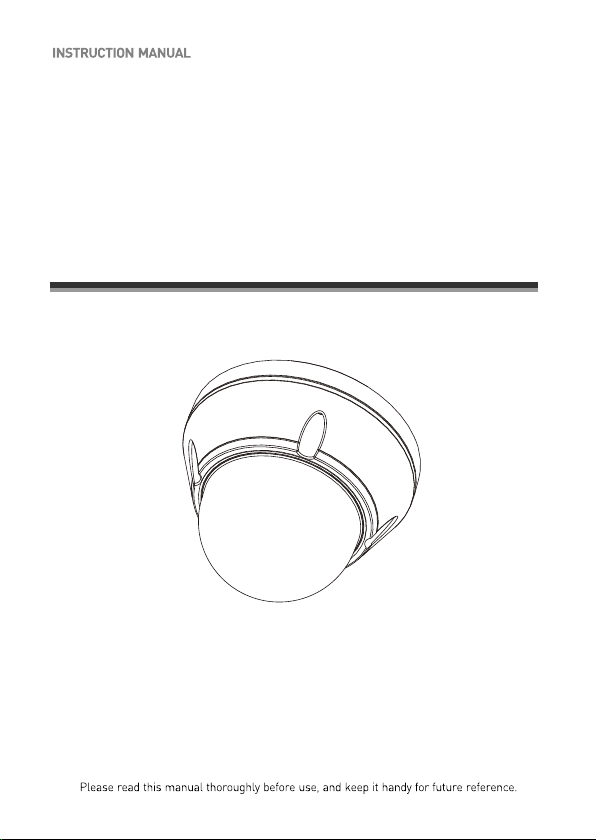
600TV Lines
Ultra High Resolution Color Camera
3-AXIS VANDAL RESISTANT
DOME CAMERA
Page 2
WARNINGS AND CAUTIONS:
CAUTION:
CAUTIONCAUTION
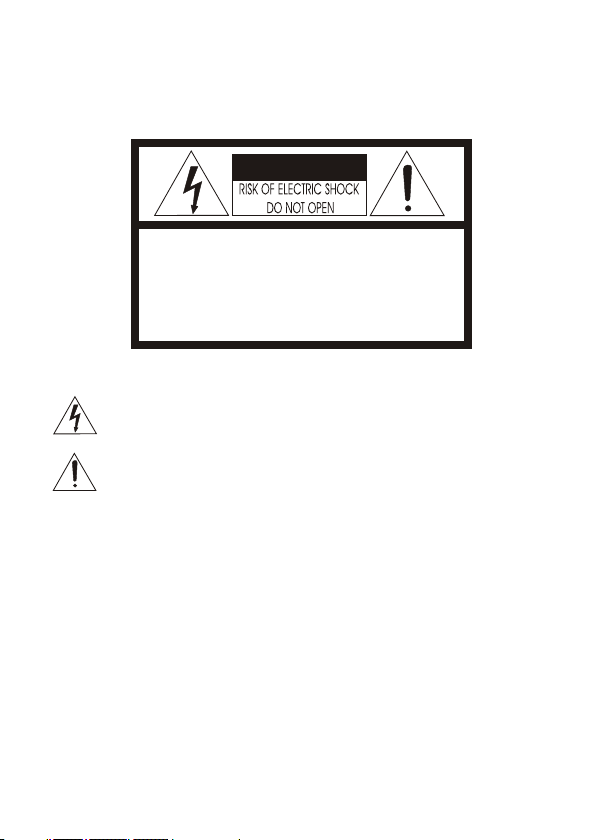
CAUTION: TO REDUCE THE RISK OF ELECTRIC SHOCK,
DO NOT REMOVE COVER(OR BACK).
NO USER-SERVICEABLE PARTS INSIDE.
REFER SERVICING TO QUALIFIED SERVICE PERSONNEL.
EXPLANATION OF GRAPHICAL SYMBOLS
The lightning flash with arrowhead symbol, within an equilateral triangle, is
intended to alert the user to the presence of uninsulated "dangerous voltage"
within the product's enclosure that may be of sufficient magnitude to constitute a
risk of electric shock to persons.
The exclamation point within an equilateral triangle is intended to alert the user to
the presence of important operating and maintenance (servicing) instructions in the
literature accompanying the product.
Should any liquid or solid object fall into the cabinet,
unplug the unit and have it checked by the qualified
personnel before operating it any further.
Unplug the unit from the wall oulet if it is not going to
be used for several days or more. To disconnect the
cord, pull it out by the plug. Never pull the cord itself.
Allow adequate air circulation to prevent internal heat
build-up. Do not place the unit on surfaces (rugs,
blankets, etc.) or near materials(curtains, draperies)
that may block the ventilation holes.
Height and vertical linearity controls located at the
rear panel are for special adjustments by qualified
personnel only.
Do not install the unit in an extremely hot or
humid place or in a place subject to excessive
dust, mechanical vibration.
The unit is not designed to be waterproof.
Exposure to rain or water may damage the unit.
Clean the unit with a slightly damp soft cloth.
Use a mild household detergent. Never use
strong solvents such as thinner or benzine as
they might damage the finish of the unit.
Retain the original carton and packing
materials for safe transport of this unit in the
future.
Safety ----------------------------------------- Installation -----------------------------------
Cleaning --------------------------------------
PRECAUTIONS
TO REDUCE THE RISK OF FIRE OR ELECTRIC SHOCK, DO NOT EXPOSE THIS PRODUCT TO RAIN OR
MOISTURE. DO NOT INSERT ANY METALLIC OBJECTS THROUGH THE VENTILATION GRILLS OR
OTHER OPENINGS ON THE EQUIPMENT.
ii
Page 3
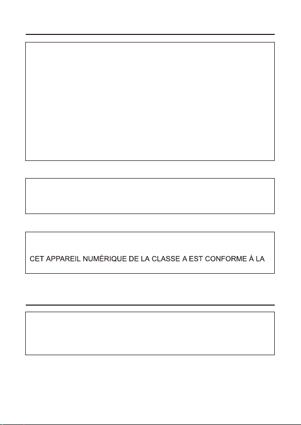
FCC INFORMATION : THIS EQUIPMENT HAS BEEN TESTED
AND FOUND TO COMPLY WITH THE LIMITS FOR A CLASS A DIGITAL
DEVICE, PURSUANT TO PART 15 OF THE FCC RULES. THESE
LIMITS ARE DESIGNED TO PROVIDE REASONABLE PROTECTION
AGAINST HARMFUL INTERFERENCE WHEN THE EQUIPMENT IS
OPERATED IN A COMMERCIAL ENVIRONMENT. THIS EQUIPMENT
GENERATES, USES, AND CAN RADIATE RADIO FREQUENCY
ENERGY AND IF NOT INSTALLED AND USED IN ACCORDANCE WITH
THE INSTRUCTION MANUAL, MAY CAUSE HARMFUL INTERFERENCE
TO RADIO COMMUNICATIONS. OPERATION OF THIS EQUIPMENT IN
A RESIDENTIAL AREA IS LIKELY TO CAUSE HARMFUL
INTERFERENCE IN WHICH CASE THE USER WILL BE REQUIRED TO
CORRECT THE INTERFERENCE AT HIS OWN EXPENSE.
CAUTION : CHANGES OR MODIFICATIONS NOT EXPRESSLY
APPROVED BY THE PARTY RESPONSIBLE FOR COMPLIANCE
COULD VOID THE USER'S AUTHORITY TO OPERATE THE EQUIPMENT.
THIS CLASS A DIGITAL APPARATUS COMPLIES WITH CANADIAN
ICES-003.
NORME NMB-003 DU CANADA.
WARNING
This is a Class A product. In a domestic environment this product
may cause radio interference in which case the user may be required
to take adequate measures.
CE COMPLIANCE STATEMENT
FCC COMPLIANCE STATEMENT
iii
Page 4
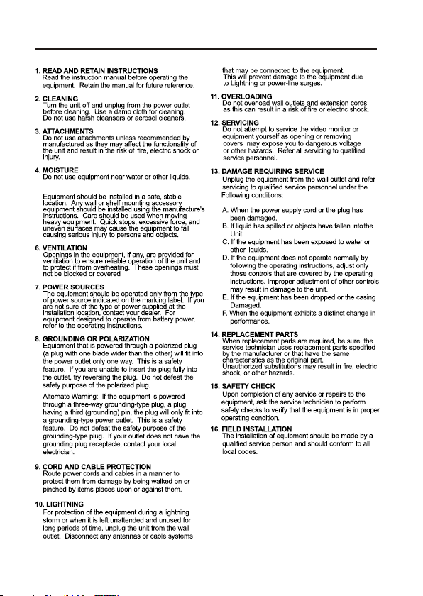
IMPORTANT SAFEGUARDS
1 -1 Class 2 power source only.
7
-2 Do NOT use power source other than that specified.
17
17. CAUTIO N-these servicing instruct ions are
fo r us e by qual ified service personnel only.
to redu ce the ri sk of el ectric shock do not
pe rform any servicin g ot her than that containe d
in th e op er ating instru ctions unless you are
qual ified to do so .
5. ACCESSORIES
iv
Page 5

1
The camera provides high-quality images using SONY CCD technology especially designed for
applications.
closed-circuit television (CCTV) and security surveillance
Features:
High resolution and high performance 1/3" SONY Super HAD CCD
Technology
Excellent picture quality
600 lines(Color) of resolution
0.1 lux(Color), 0.04 lux(B/W) @ F1.2 50IRE Sensitivity
Auto electronic shutter [1/60(1/50) ~ 1/120,000] and manual electronic
shutter modes
OSD (On Screen Display)
3D DNR Function
Eclipse
DRC (Dynamic Range Control)
Auto and manual white balance modes
BLC (Back Light Compensation)
Day&Night (Auto / DAY / NIGHT / EXT)
Private Mask (24 Poisition, BW, Color, Mosaic)
AGC (Auto Gain Control)
Sense-up (x2 ~ x256)
MIRROR (NORMAL /MIRROR/VERTICAL /ROTATE)
VIDEO OUT(BNC, UTP(Option))
Motion Detection
Internal / AC line lock
RS485 CONTROL
2.8~12
Operates in 12 VDC or 24 VAC
Use Certified / Listed Class 2 power supply only.
Camera Mount : camera mount directily to the wall or ceiling
mm A/I Varifocal Lens F1.4~3.4
INTRODUCTION
Test Monitor Output
(EXT : D&N with ICR model option)
(D&N Lens option)
(Sense up x 256 -
0.0004 lux(Color), 0.0001 lux(B/W))
Page 6

2
CAMERA CONNECTIONS
REMINDER:
Never aim the camera directly into the sun.
CONTENTS of PACKAGE
The package contains the following.
Camera in Housing 1
Instruction Manual (This Document) 1
Accessory Kit for Installing 1
1Drilling guide label
2 31
4
6
5
1. Lens : 2.8~12mm A/I Vari-focal lens for wide area monitoring.
2. Power : 24V AC input / 12V DC input
power source from a DC 12V or AC 24V ac +/-10% 60/50Hz +/-1Hz
Use Certified/Listed Class 2 power supply transformer only.
*If using DC 12V power adaptor,
use a power supply capable of supplying 6 Watts.
(Dry contact)
3. IR EXT : Only D&N with ICR model.
4. RS485 CONTROL
5. UTP : Video out (option)
6. Video : BNC connector used to connect the camera to a monitor, switcher, etc.
NOTE :
When D&N EXT mode is used, be careful not to confuse the IR EXT wires with the UTP wires.
An incorrect connection will cause malfunction.
OPT ION
Onl y D &N
Onl y D &N
Opt ion
Opt ion
(D&N with ICR model option)
(D&N with ICR model option)
Page 7

INSTALLATION
Figure 1
Torx screws
M5x10 (4x)
Figure 2
Seal around
the housing
base tightly using
the silicon rubber
Figure 3
Drilling
Guide Label
Plastic Anchor(4x)
Rubber Washers(4x)
Mounting Screw
M6X35(4x)
3
1. Loosen the four torx screws located midway up the front of the housing leave the screws
intact in the front portion. (Fig. 1)
2. Drill the mounting location using the supplied drill guide label. (Fig. 3)
3. Attach the housing to the ceiling using suitable fasteners, M6x35 tapping screws are
supplied only use if they are suitable. (Fig. 3)
4. Closing the housing using the loosen torx screws. (Fig. 2)
CEILING / WALL
Page 8

4
The housing can also
be mounted on a 4s or 2s
electrical box.
MOUNTING HOUSING TO
AN ELECTRICAL BACK BOX
Electrical box
Torx screws
Rubber
Washers(4x)
- Vi deo out check-
U
P
D
O
W
N
ENTER
E
L
F
T
G
H
T
R
I
Tact sw it ch bo ar d
Test Mo ni to r
UTP & Tact switch board
UP
DOWN
ENTER
LEFT
RIGHT
Page 9

5
CAMERA ADJUSTMENT
OSD MAIN SCREEN
+…
▶
M E NU
EXPOSURE
WHITE BAL
DAY/NIGHT
MOTION
PRIVACY
OPTION
DISPLAY
SYNC
INITIAL
EXIT
D EF AU L T
A U T O
+…
+…
+…
+…
+…
+…
- [ENTER] ON or OFF of OSD MENU
- [UP] / [DOWM] UP or DOWN of Cursor
- [LEFT] / [RIGHT] SUB MENU ON or Decision
1) EXPOSURE, WHITE BAL, DAY/NIGHT, MOTION, PRIVACY, OPTION and
DISPLAY has a SUB MENU. [UP]/[DOWN] of Cursor.
And SUB MENUS is displayed by [LEFT] / [RIGHT].
2) SYNC : AUTO or INT can be selected.
4) To EXIT the menu use the [LEFT] / [RIGHT] buttons when EXIT is highlighted.
3) When making INITIAL from USER to DEFAULT, all data is initialized.
Page 10

6
▶
M E NU
EXPOSURE
WHITE BAL
DAY/NIGHT
MOTION
PRIVACY
OPTION
DISPLAY
SYNC
INITIAL
EXIT
EXPOSURE
LENS
BRIGHTNESS
BACKLIGHT
SHUTTER
AGC
SENSE UP
ECLIPSE
3D-DNR
DRC
RETURN
▶
WHITE BAL
WB MODE
RED CONT
BLUE CONT
PUSH AUTO
RETURN
▶
MOTION
DETECT MODE
DETECT AREA
SENSITIVITY
ALARM TIME
RETURN
PRIVACY
AREA
MASK
MODE
LEVEL
TOP
DOWN
LEFT
RIGHT
RETURN
▶
▶
DAY/NIGHT
D/N MODE
AUTO LEVEL
FILTER DLY
S I N
SEN O R
BURST
RETURN
▶
OPTION
TITLE
NEGA/POSI
SHARPNESS
MIRROR
ZOOM
PAN/TILT
PHASE
RETURN
DISPLAY
TITLE
MOTION DET
CAMERA ID
PROTOCOL
BAUDRATE
SAVE
RETURN
▶
▶
***
SENSOR IN : Only D&N with ICR model (option)
***
Page 11

7
1) LENS
2) BRIGHTNESS
3) BACKLIGHT
4) SHUTTER
5) AGC
6) SENSE UP
7) ECLIPSE
8) 3D-DNR
9) DRC
10) RETURN
DC, ELC can be selected.
0 to 60 can be selected.
Level setting is available in DC, ELC mode.
*
ON or OFF can be selected. (BLC level, location)
Prevents such a back light effect to secure a clear image under
*
all illumination environments.
1/60 (1/50), FLC, 1/250, 1/500, 1/1000, 1/2000, 1/4000,1/10000
1/30000, 1/60000, 1/120000 sec.
When LENS is DC, it is possible to select it.
*
Another becomes NOT USE.
AGC OFF, LOW, MID, HIGH can be selected.
As the level of gain increases, the screen gets brighter and the level
*
Of noise also increases.
OFF, x2, x4, x8, x16, x32, x64, x128, x256 can be selected.
SENSE UP helps maintain a bright, clear screen image
*
by automatically detecting change in the level of light
ON or OFF can be selected.
The function improves the identification capability of subjects facing
*
a brightly lit situation by filtering out the strength of the light.
can be selected.
Reduces the noise on the screen under low light condition
*
The function to visibly brighten a subject in a dark area
*
Return to MAIN MENU.
OFF, LOW, MID, HIGH
ON or OFF can be selected.
<EXPOSURE>
Press the [LEFT] or [RIGHT] button to access the "EXPOSURE" mode.
<WHITE BALANCE>
Press the [LEFT] or [RIGHT] button to access the "WHITE BALANCE" mode.
- ATW
- AWC
- INDOOR
- OUTDOOR
2) RED CONT
3) BLUE CONT
4) PUSH AUTO
5) RETURN
- MANUAL
This mode can be used within the color temperature range
1.800°K ~ 10.500°K
Please press the [LEFT] or [RIGHT] button in the PUSH AUTO mode
while the camera is directed at a piece of while paper to obtain the
optimum state under current illumination.
If the environment including the light source is
changed, you have to adjust the White balance again.
Set the color temperature to 3200˚K
Adjust Red Gain Value (0 ~ 127)
Can be adjust while in manual mode.
Adjust BLUE Gain Value (0 ~ 127)
Can be adjust while in manual mode.
When it is AWC, OFF to PUSH can be selected.
Return to MAIN MENU.
Manual mode. User can change R and B Gain manually.
Set the color temperature to 6300˚K
1) WB MODE
Page 12

8
<DAY/NIGHT>
Press the [LEFT] or [RIGHT] button to access the "DAY/NIGHT" mode.
1) D/N MODE
- AUTO
- DAY
- NIGHT
- EXT
2) AUTO LEVEL
3) FILTER DLY
4) SENSOR IN
5) BURST
AUTO, DAY, NIGHT, EXT can be selected.
This camera has a function which automatically changes to
the appropriate mode for day-time or night-time.
In this mode, the camera outputs the video image only in color.
In this mode, the camera outputs the video image only in black and white.
In this mode, an external signal changes the camera output from the
COLOR mode to BW mode and back.
When set to AUTO, the 0 to 3 values can be selected.
AGC LOW : 0 AGC MID : 0 ~1 AGC HIGH : 0 ~3
*
When set to AUTO, 4 to 10 can be selected.
When AGC is OFF, NOT USED.
Adjust the delay time of filter movement when changing
*
from on to off or off to on
.
When it is EXT, No or NC Can be selected.
When it is DAY, Not Use.
Another mode be comes ON or OFF can be selected.
<MOTION>
Press the [LEFT] or [RIGHT] button to access th "MOTION"mode.
1) DETECT MODE
2) DETECT AREA
3) SENSITIVITY
4) ALARM TIME
5) RETURN
ON or OFF can be selected.
Turning on becomes invalid while displaying OSD.
*
However, it becomes effective only at MOTION AREA.
MOTION AREA is displayed.
0 to 8 can be selected.
1 to 60 sec can be selected.
Return to MAIN MENU.
<PRIVACY>
Press the [LEFT] or [RIGHT] button to access the “PRIVACY” mode.
1) AREA
2) MASK
3) MODE
4) LEVEL
5) TOP
6) DOWN
7) LEFT
8) RIGHT
9) RETURN
1 to 24 can be selected.
ON or OFF can be selected.
When MASK is ON, BW, MOSAIC, COLOR can be selected.
- BW : 0 to 15 can be selected.
- MOSAIC : SMALL or MIDDLE or LARGE can be selected.
- COLOR : RED, BLUE, GREEN, YELLOW, CYAN, MAGENTA
can be selected.
When MASK is ON, 3 to 124(NTSC) or 6 to 150(PAL) can be selected.
When MASK is ON, 5 to 126(NTSC) or 8 to 152(PAL) can be selected.
When MASK is ON, 0 to 187(NTSC) or 0 to 185(PAL) can be selected.
When MASK is ON, 2 to 189(NTSC) or 2 to 187(PAL) can be selected.
Return to MAIN MENU.
*EXT : Only D&N with ICR Model (Option)
*SENSOR IN : Only D&n with ICR Model.(Option)
Return to MAIN MENU.
6) RETURN
Page 13

9
<OPTION>
Press the [LEFT] or [RIGHT] button to access the "OPTION" mode.
1) TITLE
2) NEGA/POSI NEGA or POSI can be selected.
3) SHARPNESS 0 to 15 can be selected.
4) MIRROR
NORMAL, MIRROR, VERTICAL, ROTATE can be selected.
- MIRROR Horizontal image inversion
- VERTICAL Vertical image inversion
- ROTATE Horizontal image and Vertical image inversion
5) ZOOM 0FF(x1) and ON1 to ON8(x4) can be selected.
When PAN/TILT is ON, it is NOT USE.
6) PAN/TILT OFF or ON(x2) can be selected.
* When OSD MENU is OFF and PAN/TILT is ON,
o p erate by [UP],[DOWN],[LEFT],[RIGHT].
7) PHASE Sync phase is adjustable in line lock mode (Auto mode)
0 ~ 524 (NTSC) or 0 ~ 624 (PAL).
8) RETURN Return to MAIN MENU
<DISPLAY>
Press the [LEFT] or [RIGHT] button to access the "DISPLAY" mode.
TITLE
NOPQRSTUVWXYZ
ABCDEFGH I J KLM
END
POS
BS
abcdefgh i j k
l
m
nopqr
s t
uvwxyz
* /
#
! % ( ) "
_
+ - ~
; .
012 3 456 78 9 :
&
A. TITLE
B. Command Line
: Move to left
: Move to right
BS : Erase a left character
POS : Change the position of the title
END : End
C. Charactor Table
: brank
: space
_
A
B
C
Page 14

10
LENS ADJUSTMENT (OPTIONAL VARIFOCAL LENS)
N
T
W
Adjust Focus
Adjust Angular Field View
Field of view: Adjust setting from Tele (T)
to Wide (W) field of View.
Focus: Adjust lens focus from near
(N) to infinity ( ).
DC AUTO IRIS LENS
Image Size 1/3" CCD
Focal Length
Aperture Ratio
Angular
Field of View
2.8-12mm
DIAGONAL
o
2.8mm : 119.9
o
12mm : 28.80
2.8-12mm 5%
1 : 1.4 5%
Black Control ( - )
White Control ( + )
Red Drive ( + )
Green Drive ( - )
LENS
Page 15

11
Power s ource
Power c onsumpt ion
Image s ensor
Total n umber o f pixel s
Scannin g syste m
Scannin g frequ ency
Sync. s ystem
Electro nic shu tter
Resolut ion
Min. il luminat ion
Video ou tput
Power input
AGC
Lens mo unt
1/3" SONY Super-HAD CCD
2:1 interlace
15.734KHz(H) x 59.94Hz(V)
Internal / Line lock
1/60 ~ 1/120,000 sec.
600 TV lines (Color)
0.1 lux(Color), 0.04 lux(B/W) @ F1.2 50IRE
0.0004 lux(Color), 0.0001 lux(B/W))
(Sense up x 256 -
More than 55dB (AGC OFF, Sense up OFF)
AUTO / DAY / NIGHT / EXT
INITIAL / EXIT(Auto save) / RETURN
f=2.8~12mm F1.4~3.4
Varifocal DC auto iris
795(H) x 596(V)
2-Pin wire
Fixed mount
NTSC
3.5 Watts
811(H) x 508(V)
MODEL
S/N rat io
Auto Ex posure
Lens
Sense-u p
BLC
Privacy zone
Day & Ni ght
White B alance
Display Title
Motion detection
SPECIFICATIONS
Power
15.625KHz(H) x 50Hz(V)
1/50 ~ 1/120,000 sec.
Lens
Connect or
&
etc.
PAL
Video o utput
Operati ng Temperature
1.0 Vp-p (75 ohm, composite)
DC / ELC
ATW / AWC / MANUAL / INDOOR / OUTDOOR
OFF / x2 ~ x256
ON / OFF (Position, Level)
OFF / ON (24position, Mask BW, Color, Mosaic)
POSI / NEGA
OFF / ON (Sensitivity & Alarm time Selective)
BNC connector, UTP(option)
o o o o
]
-10 C ~ +50 C [14 F ~ 122 F
General
Camera Control
RS485(Fastrax, Pelco D, Pelco P),Tact switch
OFF / LOW / MIDDLE / HIGH
OFF / ON
Sharpne ss
Preset
Mirror
Video Pi cture
0~15
NORMAL / MIRROR / VERTICAL / ROTATE
Zoom
INT/AUTO
Operati ng humi dity
0 ~ 96% (non-condencing)
f=2.8~12mm F1.4~3.4
Varifocal DC auto iris ICR
Sync
OFF /ON(x4) / PAN&TILT(x2)
-Day/Night A/I Varifocal 4~9mm Lens is optional
1/60(1/50) / FLICKERLESS / MANUAL SHUTTER
(1/250,1/500,1/1000,1/2000,1/4000,1/10000,1/30000,1/60000,1/120000)
Brightn ess
0 ~ 60
F
U
N
C
T
I
O
N
Camera ID
Baudrat e
IR EXT IN
1 ~254
2400 / 4800 / 9600 / 19200
NC / NO
Eclipse
3D-DNR
DRC
OFF / ON
OFF / LOW / MIDDLE / HIGH
ON / OFF
(EXT : D&N with ICR model option)
(Only D&N with ICR model option)
Page 16

EXTERNAL DIMENSION
Dimensions
Window Size
Cable Entry
Weight - Unit:
Shipping:
Uni t: mm
0.1 in. (2.5mm thick),
impact-resistant P.C (LEXAN)
3.93 in. (10cm) diameter
One 1" opening holes
1.54 lb. (0.7kg)
2.11 lb. (0.96 kg)
146.3
PF 3/4"
TAP
o
4
5
o
4
5
1
.
0
1
2
113. 7
.
4
-
6
4
50302593A
600TV Lines Ultra High Resolution
Color Camera
 Loading...