

Page 1
REVO America
1-800-6250-REVO (7386)
User Manual
700 Freeport Parkway Suite 100
Coppell, TX 75019
Model RESPTZ37-SERIES
24 VAC @ 60 Hz, 12W NTSC
Publication No. RESPTZ37-10B
Copyright © 2013 REVO America Inc. All rights reserved.
REVO and its logo are trademarks of REVO America Inc.
Page 2

REVO America
1-800-6250-REVO (7386)
CAUTION
can be used outdoors.
REVO America wants to ensure that your installation experience is a safe and pleasant one. Please
read and adhere to these Safety Instructions.
Model RESPTZ37-1 is an indoor camera and not meant for outdoor use. Models
RESPTZ37-1HSC and RESPTZ37-1HSW are provided with weather-proof enclosures and
1. Never perform any installation procedure or open the camera case with power on.
2. Pay attention to the Warnings and Cautions in the instructions. They are there for
your safety and to ensure that the equipment does not get damaged.
3. Do not discard this manual after installation. You may need to reference it in the
future.
4. Use a Certified/Listed Class 2 power supply only.
5. Do not block any ventilation openings. Install in accordance with the
manufacturer’s instructions.
6. Do not install near any heat sources such as radiators, heat registers, stoves, or
other apparatus (including amplifiers) that produce heat.
7. Do not defeat the safety purpose of the polarized or grounding-type plug. A
polarized plug has two blades with one wider than the other. A grounding type
plug has two blades and a third grounding prong. The wide blade or the third
prong are provided for your safety. If the provided plug does not fit into your
outlet, DO NOT MODIFY THE PLUG OR OUTLET. Consult an electrician for
replacement of the obsolete outlet.
8. Protect the power cord from being walked on or pinched particularly at
plugs, convenience receptacles, and the point where they exit from the
apparatus.
9. Only use attachments/accessories specified by the manufacturer.
10. Do not submerge the camera in water or any liquid.
11. Refer all servicing to qualified service personnel. Servicing is required when the
apparatus has been damaged in any way, such as power-supply cord or plug is
damaged, submerged in liquid, does not operate normally, or has been dropped.
Model RESPTZ37-SERIES
700 Freeport Parkway Suite 100
Coppell, TX 75019
Copyright © 2013 REVO America Inc. All rights reserved.
REVO and its logo are trademarks of REVO America Inc.
Page 3
REVO America
www.revoamerica.com
RESPTZ37-SERIES
1
FCC Compliance
WARNING
of electric shock.
CAUTION
avoid damage to the equipment or loss of data.
FCC INFORMATION: This equipment has been tested and found to comply with the limits for a Class A
digital device, pursua nt to Part 15 of the FCC rules. T hese limits are desig ned to provide reas onable protection
against harmful interference when the equipment is operated in a commercial environment. This equipment
generates, uses, and can radiate radio frequency energy and if not installed and used in accordance with the
instruction manual, may cause harmful interference to radio communications. Improper operation of this
equipment in a reside ntial area is likely to cause harmful interference in which case the user will be required to
correct the interference at his or her o wn expens e.
CAUTION: Changes or modifications not expressly approved by the party responsible for compliance could
void the user's authority to operate the equipment.
This Class A digital apparatus complies with Canadian ICES-003.
Cet appareil numérique de la classe a est conforme à la norme NMB-003 du Canada.
CE Compliance
WARNING: T his is a Class A product. In a domes tic environment this pr oduct may cause radi o interference in
which case the user may be required to take adequate measures.
The lightning flash within an equilateral triangle is intended to alert the user to the
presence of dangerous voltage that may be of significant magnitude to constitute a risk
The exclamation point within an equilateral triangle is intended to alert the user to the
presence of important operating or maintenance instructions that should be noted to
Page 4

REVO America
www.revoamerica.com
RESPTZ37-SERIES
2
C
o
o
ntt
n
C
Features ............................................................................................................................................................................ 3
What’s in the Box ............................................................................................................................................................. 4
Settings ............................................................................................................................................................................. 6
Setting Camera Termination ........................................................................................................................................ 7
Fail-Safe Network ......................................................................................................................................................... 8
Setting Camera Address ............................................................................................................................................... 9
Figure 4. Setting Camera Addresses ........................................................................................................................... 10
Setting Camera Protocol, Video Standard, Baud Rate and Parity (Optional) ............................................................. 10
Dimensions ..................................................................................................................................................................... 13
e
e
ntt
n
s
s
Installation ...................................................................................................................................................................... 14
Considerations ............................................................................................................................................................ 14
Tools Required ............................................................................................................................................................ 14
Installing the Camera .................................................................................................................................................. 15
Wiring ......................................................................................................................................................................... 15
Camera Configuration .................................................................................................................................................... 18
Getting Started ........................................................................................................................................................... 18
Understanding the Dome Menu ................................................................................................................................. 20
Camera ....................................................................................................................................................................... 21
Dome Setup ................................................................................................................................................................ 27
Specifications .................................................................................................................................................................. 38
Troubleshooting ............................................................................................................................................................. 39
Glossary .......................................................................................................................................................................... 41
Page 5

REVO America
www.revoamerica.com
RESPTZ37-SERIES
3
F
TIP
e
e
att
a
F
• 37X optical zoom PTZ dome camera
• Three models are offered: I ndoor Flush Mount, Outdoor Wall Mount
and Outdoor Ceiling Mount
• Superb resolution of 650 TV lines provides high-qual i ty video day
or night
• High-end features such as Presets (240), Tours (8), Auto Scan (17)
and Patterns (8) normally found in came ras costing thousands
more
• Day/Night camera with True Night Shot feature
• Built-in motion detection
urr
u
e
e
s
s
• 8 Alarm inputs and 4 Alarm outputs
• Easy-to-use menu system allows setup in minute s
• Wide optical range with PTZ provides coverage of large areas with
just one camera
• Variable speeds for PTZ func ti ons : Slow, Normal and Turbo enable
you to customize camera opera ti on
• Titling so you can identify up to 16 camera locations
• IP66 rated for durability, vandal resistance and operation in dusty
or wet environments (Outdoor models )
Browse the entire manual prior to installing the camera. There is a lot of useful
information and tips that will help you to install your system effectively.
Page 6
REVO America
www.revoamerica.com
RESPTZ37-SERIES
4
W
W
The RELPTZ37 Series consists of three models that are preconfigured as follows:
h
att’’
h
a
Model RESPTZ37-1 Indoor Flush-Mount Dome Camera
s ii
s
n tt
n
h
h
e
e
B
B
o
o
x
x
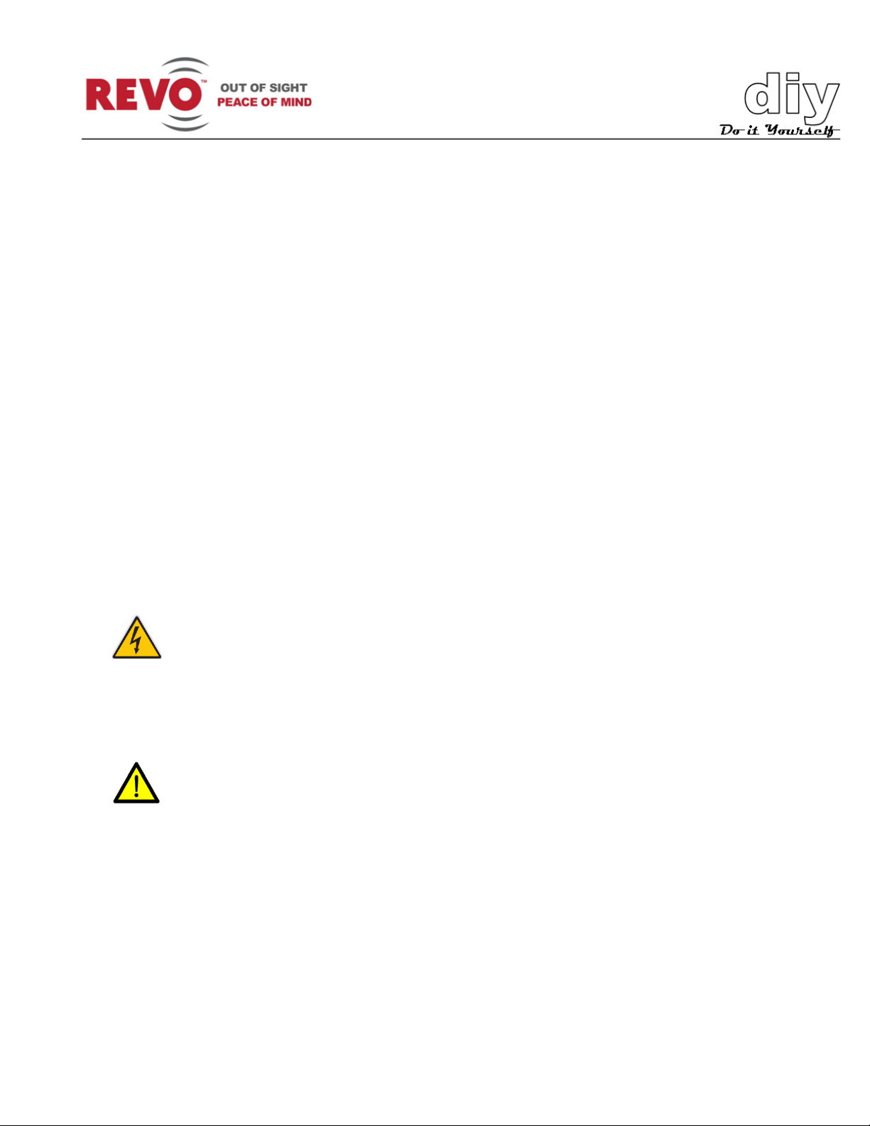
Model RESPTZ37-1HSC Outdoor Ceiling-Mount Dome Camera
Page 7
REVO America
www.revoamerica.com
RESPTZ37-SERIES
5
Model
Manual
RESPTZ37-1 Indoor Flush-Mount Dome Camera
HCS251-HV
RESPTZ37-1HSC Outdoor Ceiling-Mount Dome Camera
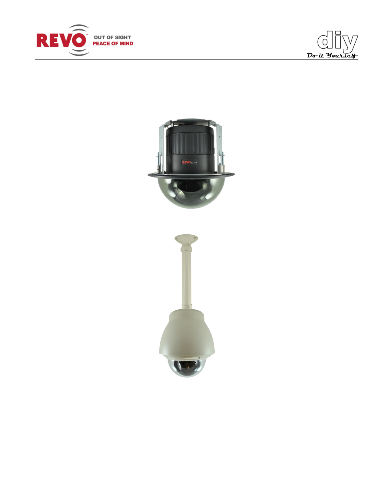
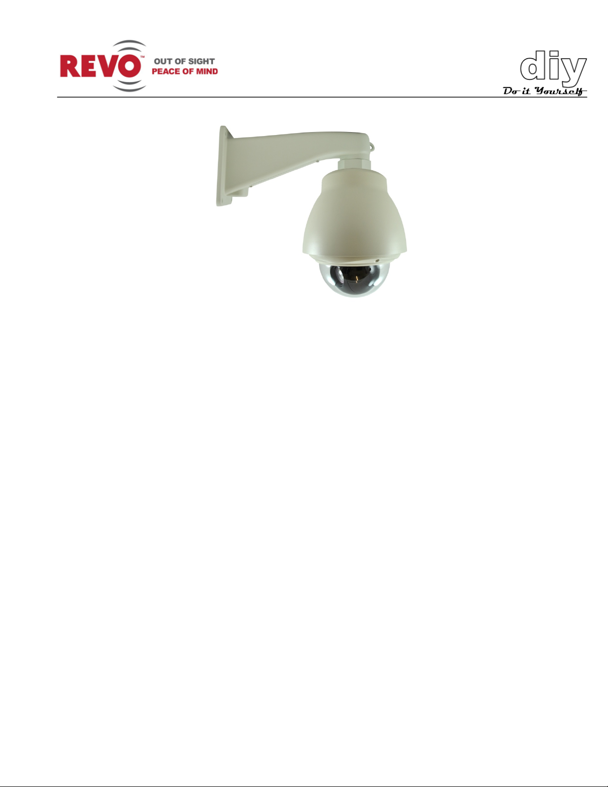
RESPTZ37-1HSW Outdoor Wall-Mount Dome Camera
Model RESPTZ37-1HSW Outdoor Wall-Mount Dome Camera
Each model is provided with mounting hardware and installation guide. Refer to the following
manuals for installation and mounting instructions.
RESPTZH-1
Page 8
REVO America
www.revoamerica.com
RESPTZ37-SERIES
6
S
TIP
NOTE
will be communication errors.
ettttii
S
e
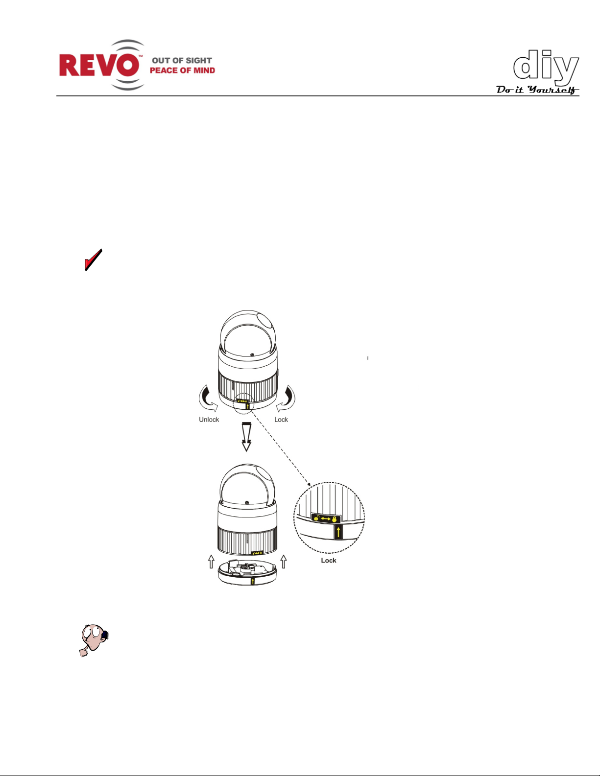
Prior to installing the camera, you must set it up for use in the video system. To do this you will
need to access the switches on the bottom of the camera. Remove the camera from the box and
the enclosure. To access the switches, you must remove the bottom cover as shown in Figure 1.
n
n
g
g
s
s
Use a small paper clip to set the DIP switches to ensure that you s et each one correctly.
Figure 1. Removing Bottom Cover
Setting DIP switches correctly is very important. If you do not set them correctly, there
Page 9
REVO America
www.revoamerica.com
RESPTZ37-SERIES
7
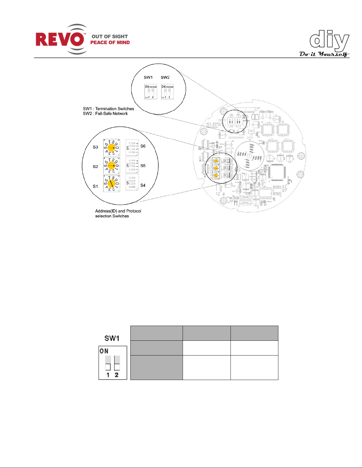
SW1 1 2
Terminated
ON
ON
Not
OFF
OFF
Figure 2. Switch Layout
Setting Camera Termination
When you set up your video system, you will be connecting the cameras, keyboard controller and
any other devices in a daisy-chain arrangement (as shown in Figure 3). All of the devices are set
up in a line. The last device in the line must be set so that the control device knows it is the last
device. Set this using DIP switch SW1 (Figure 2). If this camera is to be the last device, set SW1
DIP switches 1 and 2 to ON as shown below. If it is not the last device, set the switches to OFF.
terminated
Page 10
REVO America
www.revoamerica.com
RESPTZ37-SERIES
8
TIP
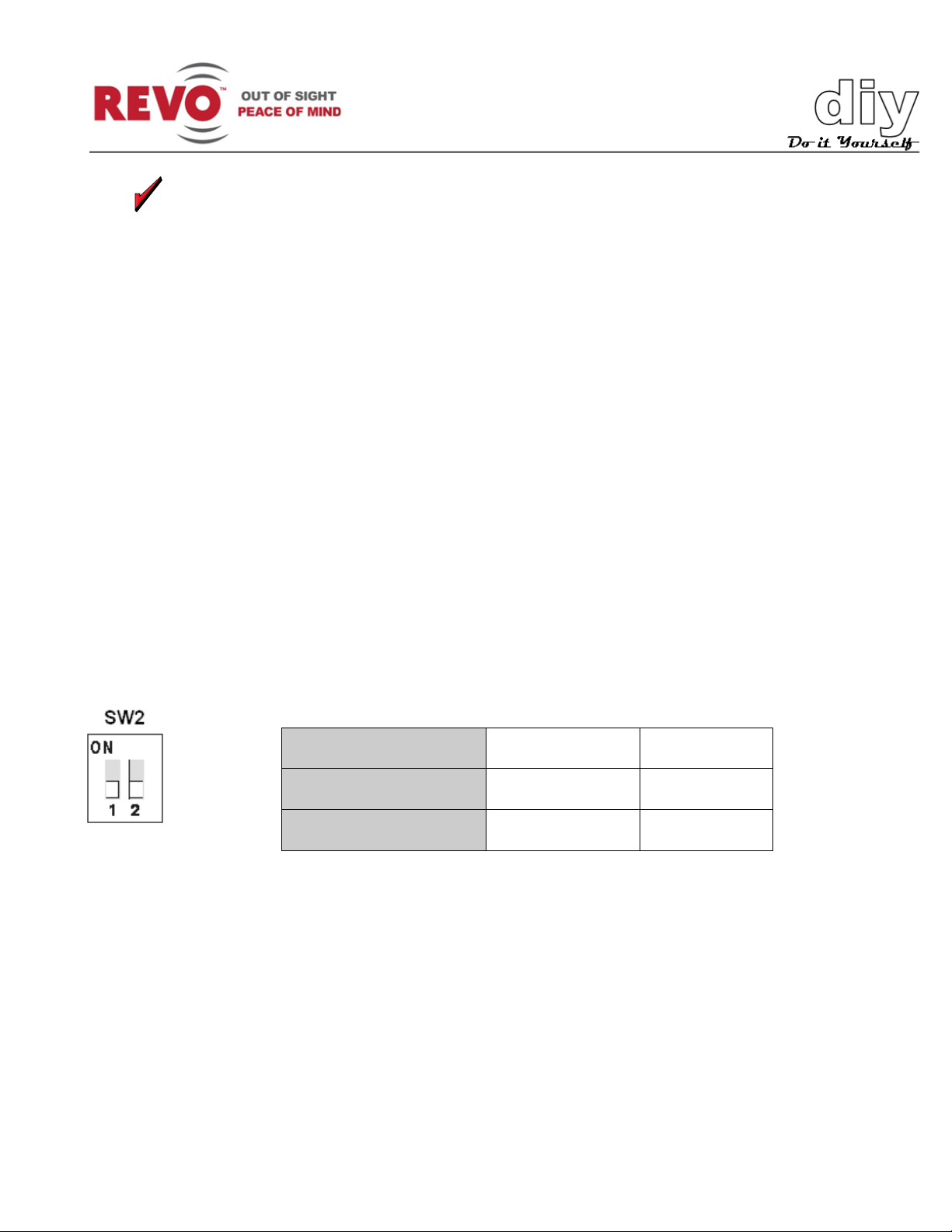
SW2
1
2
ON
PULL-UP
PULL-DOWN
OFF
NONE
NONE
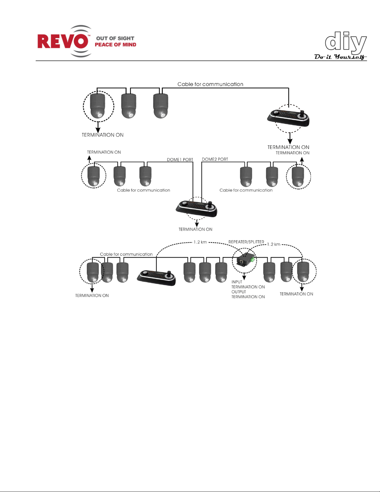
Set up all of your devices now to ensure that you only have one selected as the last
device. Record the device, which is the last device for future reference.
Fail-Safe Network
The camer a may be controlled by both REVO and non-REVO devices such and keyboard
controllers or DVRs. Using these devices, you can set up the camera and all of the functions. The
ideal way to do this is using a REVO keyboard. It provides the easiest way to take full advantage
of the camera’s capabilities. It also provides a fail-safe network by protecting the camera if any of
the following conditions occur:
• When the RS-485 circuit is open (Break)
• When the RS-485 circuit is shorted
• When RS-485 circuit is damaged
When a non-REVO device is used, there also may be some problems with the communication
between the camera and controller device. To compensate for this, set DIP switch SW2 poles 1
and 2 (Figure 2) to ON in the camera closest to the controller device. Typical connections are
shown in Figure 3.
See Setting Camera Protocol and Video Standard for additional instructions on using non-REVO
keyboard controllers or DVRs.
Page 11
REVO America
www.revoamerica.com
RESPTZ37-SERIES
9
Figure 3. Termination Connections for Various Camera Configurations
Setting Camera Address
Each camera requires a unique camera address so that the control device knows which camera is
at your back door and which camera is monitoring your driveway. Think of the camer a ad d r es s as
a telephone number. In order for the video system to work with multiple cameras, it has to know
which one is which.
Switches S1 through S3 (Figure 2) are used to set the camera address. Apply the settings for
each camera in your video system as shown in the following table. Up to 999 cameras may be set
up.
Page 12
REVO America
www.revoamerica.com
RESPTZ37-SERIES
10
NOTE
communication errors.
D
ID
S3
S2
S1 1 0 0 1
2 0 0
2
1
2
3
4
5
6
7
8
9
0
8
1
1
2
3
4
5
6
7
8
9
0
8
1
1
2
3
4
5
6
7
8
9
0
8
1
S3
S2
S1
This is an important step. If you do not set the camera addresses correctly, there will be
OME
Figure 4. Setting Camera Addresses
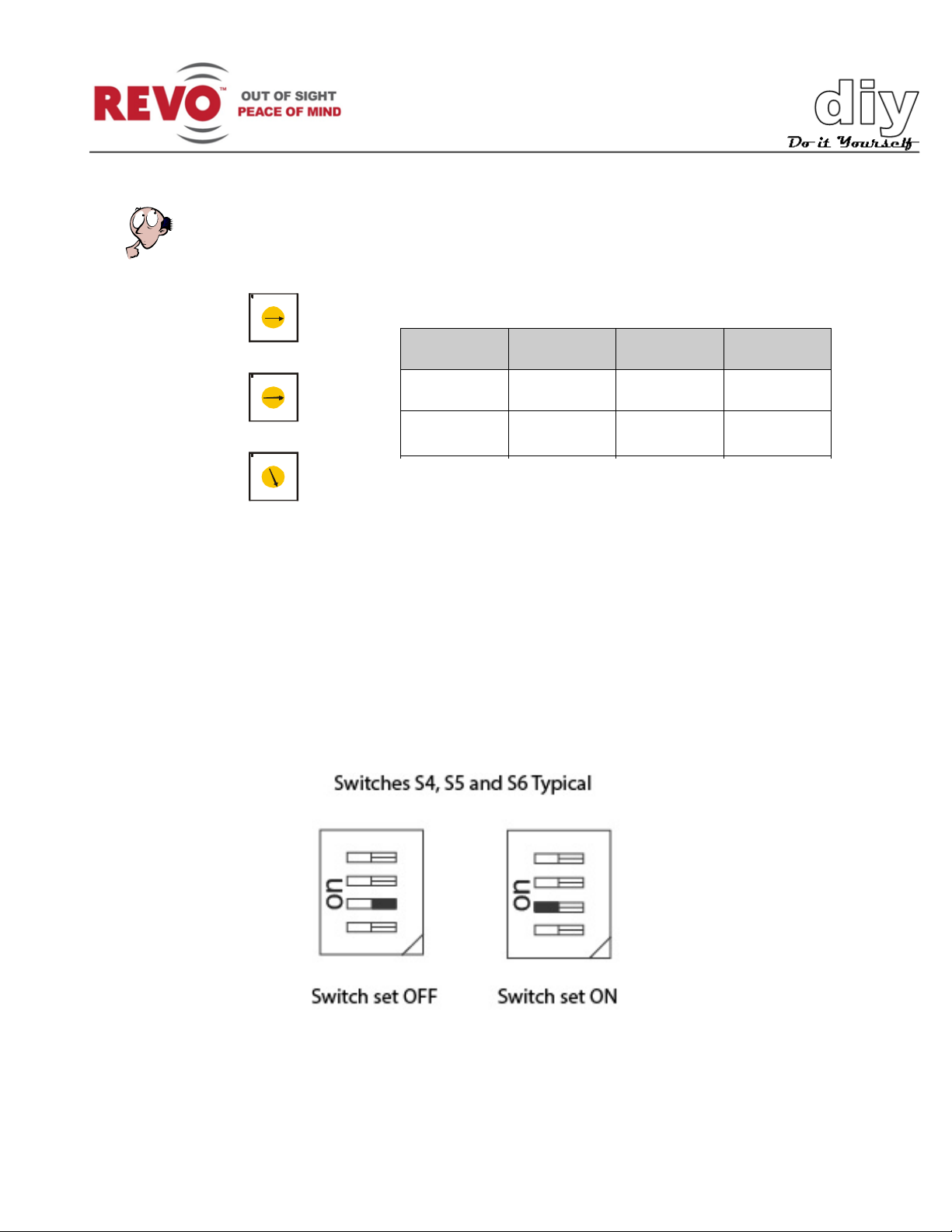
Setting Camera Protocol, Video Standard, Baud Rate and Parity (Optional)
If you are using a REVO America keyboard controller and using the camera in the United States
or other NTSC standard country, there is no n eed to c hange the default settings of switches S4,
S5 and S6 (Figure 2). You can use the default settings.
If you need to make changes, see the setting options that follow. The switches are se t as follows:
Page 13
REVO America
www.revoamerica.com
RESPTZ37-SERIES
11
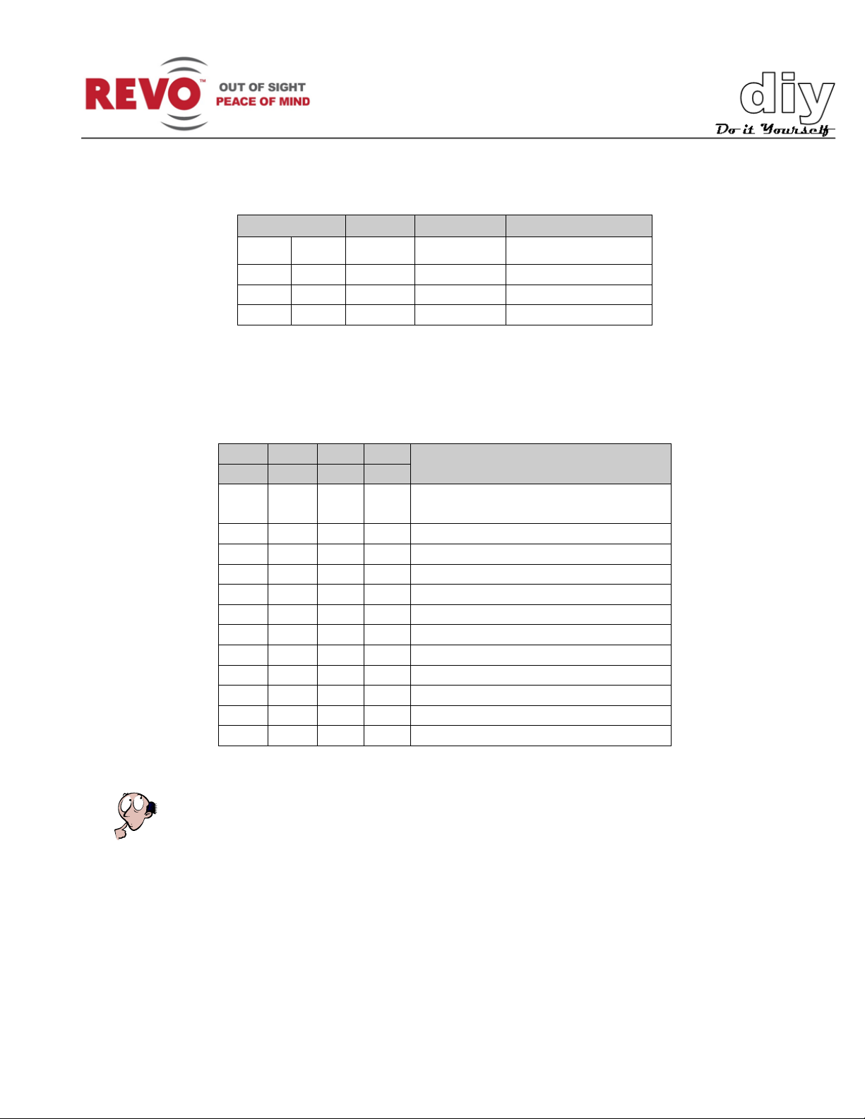
The following settings are used for the Alarm function enable/disable (S4-1), PAL/NTSC selection
S/W
On
Off
FUNCTION
D1
S4-1
D2
S4-2
PAL
NTSC
NTSC/PAL
D3
S4-3
Default
Reserved
D4
S4-4
RS-422
RS-485
RS-422/RS-485
D5
D6
D7
D12
S5-1
S5-2
S5-3
S6-4
F2,REVO TRAX,
Pelco-D,Pelco-P(Default)
Off
Off
On
Off
F2,REVO TRAX
Off
On
Off
Off
Sensormatic RS422
Off
On
On
Off
Pelco-D, Pelco-P
On
Off
Off
Off
Vicon
On
Off
On
Off
Ernitec
On
On
Off
Off
Reserved
On
On
On
Off
F2
Off
Off
Off
On
Philips(Bosch)
Off
Off
On
On
Reserved
Off
On
Off
On
Dynacolor
Off
On
On
On
Reserved
NOTE
defaults listed above.
(S4-2), and RS-422/RS-485 selection (S4-4). Set the switches as indicated in the table below.
Enable Disable Alarm
The following settings are used to set the protocol the camera will use to communicate with the
video controller. If you are using a keyboard controller or DVR other than REVO Am er ic a, c heck
the protocol required and set switch S5 as follows :
PROTOCOL
Off Off Off Off
Some of the camera features may not be available when using protocols other than the
Page 14
REVO America
www.revoamerica.com
RESPTZ37-SERIES
12
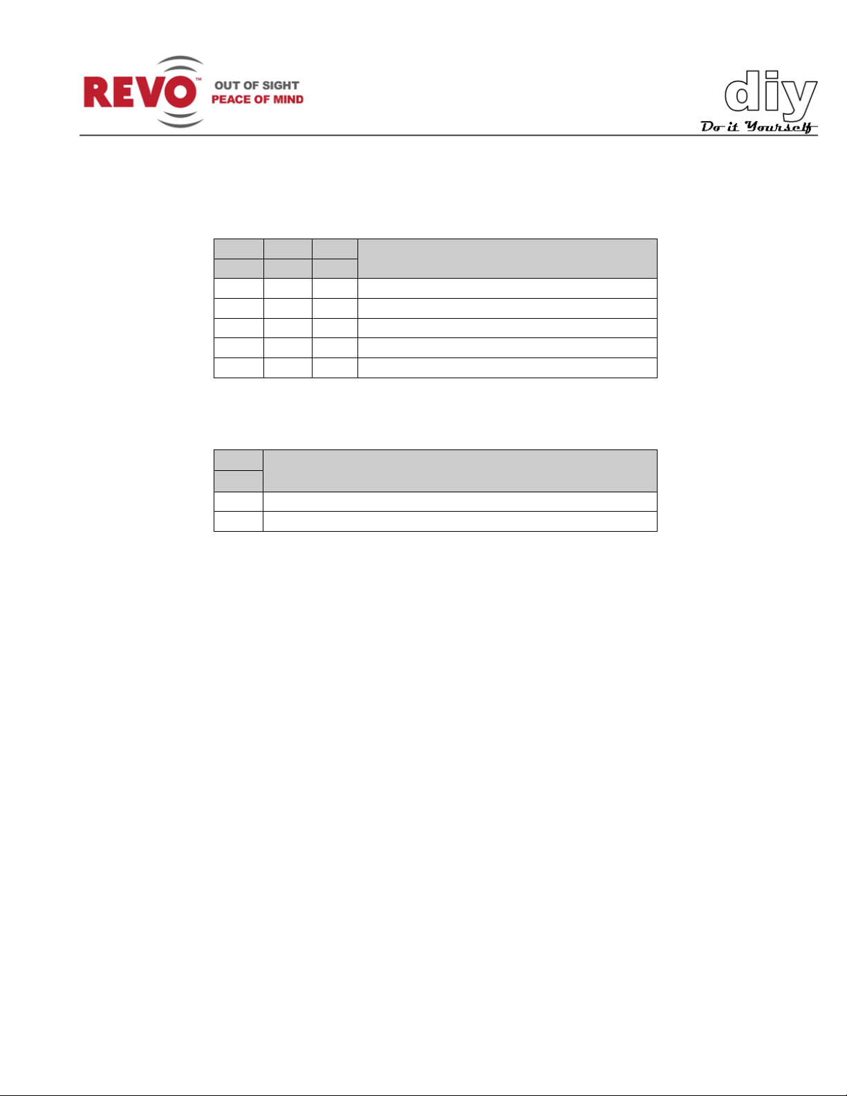
D8
D9
D10
S5-4
S6-1
S6-2
Off
Off
Off
2400 bps
Off
Off
On
4800 bps
Off
On
Off
9600 bps (Default)
Off
On
On
19200 bps
On
Off
Off
38400 bps
D11
S6-3
Off
None
On
Even
To change the BAUD rate and Parity to match your keyboard controller, set switch S5-4 and S6 as
follows:
BAUD RATE
PARITY BIT
Page 15

REVO America
www.revoamerica.com
RESPTZ37-SERIES
13
Model
Manual
RESPTZ37-1 Indoor Flush-Mount Dome Camera
HCS251-HV
RESPTZ37-1HSC Outdoor Ceiling-Mount Dome Camera
RESPTZ37-1HSW Outdoor Wall-Mount Dome Camera
Dii
D
The dimensions shown in Figure 5 are for the base camera unit. To view the dimensions for your
model, refer to the follo wing installation manual s.
m
m
e
e
n
n
sii
s
o
n
o
n
RESPTZH-1
s
s
Figure 5. Dimensions
Page 16

REVO America
www.revoamerica.com
RESPTZ37-SERIES
14
n
TIP
IIn
Considerations
You should carefully consider installation of the camera(s) to ensure a successful and easy
installation. The camera may be used indoors or outdoors (with outdoor housing), but there are
conditions that should be avoided to ensure high-quality video and avoid damage to the cameras.
Please review the following list prior to starting your installation.
• Camera Location – Cameras should be located in places where they will be protected from
direct exposure to the sun, strong light or water immersion. Exposure to any of these will
impair video quality and damage the camera.
• Wiring – The cameras are connected to the video system using coaxial cable. They require
power from a Class 2 power supply and if you choose to connect alarms or sensors, other
wiring. Make sure that you can provide the wiring to the locations that you select, and that
power is available for the power supply. Contact REVO America for all the accessories that
you will need to install the camera.
• Visibility – The cameras should be mounted so there are no obstructions or blind spots.
• Mounting – The camera should be mounted in a sturdy location capable of supporting its
weight (see specifications for your model).
stt
s
allll
a
attii
a
o
o
n
n
If this is your first time installing a video system, you may want to connect all of the
Tools Required
There are no special tools required to install the cam era. Standard flat and Philips head screw
drivers, a power drill and power saw may be required to create access for the wiring required for
the camera.
cameras and other devices to the DVR prior to installing and mounting the equipment.
This will give you the opportunity to wire the system and ensure you have everything
connected properly before you mount the cameras and run the wiring.
Page 17

REVO America
www.revoamerica.com
RESPTZ37-SERIES
15
Installing the Camera
Model
Manual
RESPTZ37-1 Indoor Flush-Mount Dome Camera
HCS251-HV
RESPTZ37-1HSC Outdoor Ceiling-Mount Dome Camera
RESPTZ37-1HSW Outdoor Wall-Mount Dome Camera
WARNING
Refer to the following manuals to install your camera model.
RESPTZH-1
Wiring
Never work with power on. You should always disconnect electrical power prior to
A typical system configuration is shown in Figure 6. Figure 7 shows the wiring connections.
installation or removal of any equipment.
Figure 6. Typical System Configuration
Page 18

REVO America
www.revoamerica.com
RESPTZ37-SERIES
16
Figure 7. Dome Camera Wiring
Page 19

REVO America
www.revoamerica.com
RESPTZ37-SERIES
17
Video Out (BNC)
Connect the video out (BNC) connector to the monitor or video input on
Power In (3-pin)
With power off, connect a certified/listed 24 VAC Class 2 power supply to
RS-485 or RS-422
The dome camera can be controlled remotely by an external device or
Alarm Inputs and
Alarm Input (AL1 thru AL8 and GND): You can use up to 8 external
on using these functions
DVR.
the dome camera connector.
Keyboard
Controller (2-pin)
Outputs (4-pin)
control system, such as a control keyboard, using RS-485 half-duplex, RS422 full duplex or simplex serial communication signals. Connect terminals
Tx+, Tx- to Tx+(Rx+) and Tx-(Rx-) of the RS485 control system.
If control system is RS-422, connect Rx+(Tx+), Rx+(Tx-) and Rx+, Rx- of
the dome camera to Rx+, Rx- and Tx+ , Tx- of the control device
respectively.
devices to trigger the dome camera to react to an event, such as a door that
has an alarm on it being opened. Mechanical or electrical switches can be
wired to the AL (Alarm In) and GND (Gr ou nd) connectors.
Alarm Output (NC/NO1 thru NC/NO4 and GND): The dome came r a can
activate up to 4 external devices such as buzzers or lights upon motion
detection. GND is the common ground.
Refer to the Programming and Operation instructi ons f or mor e in for m ati on
Page 20

REVO America
www.revoamerica.com
RESPTZ37-SERIES
18
C
ALARM DISPLAY
VIEW DIRECTION
PAN & TILT ANGLES
PRESET TITLE
FOCUS STATUS
EXPOSURE
CAMERA TITLE
CAMERA ID
a
a
m
m
C
Now that the system is installed, your next step is to configure the camera for operation. These
instructions will guide you through optimizing the camera for use and setting it up for your
installation. You can customize the camera’s movements and many oth er funct ions usi ng t he
camera’s menu system. Please note that for most applications, the default settings that your
REVO America camera has will work just fine and should not require any further adjustment.
For the purposes of describing the commands and configurations available on the camera, all
commands and operation of the camera will be initiated using a REVO America keyboard
controller. This is the ideal setup and offers the greatest flexibility and ease of operation. However,
a REVO America DVR may also be used to control the camera, as well as non REVO America
keyboard controllers or DVRs, which may be used providing you set the protocols correctly. See
the Settings section. Refer to the applicable user manual to determine the equivalent command
keys on your device.
Getting Started
err
e
a
a
C
C
o
o
nffii
n
g
g
urr
u
attii
a
o
o
n
n
Once the system is fully connected, apply power. The DVR, camera and keyboard controller will
begin a boot up routine. This will take a few minutes. Once the system is fully powered up, you
should see the following .
AREA TITLE
001 AF AE
CAMERA VIDEO
DOMEID:001
ALARM:1 W→360.0,090.0
STATUS
Page 21

REVO America
www.revoamerica.com
RESPTZ37-SERIES
19
Access the camera menu as follows:
Change value.
Joystick left or right or
Zoom handle twist
1. Log into the keyboard controller by entering the administrator’s password. On the REVO
America keyboard controller, the default password is: 9999.
2. Select camera by pressing the camera number, for example 1, and then the CAM key on
the keyboard controller.
3. Press the MENU key on the keyboard controller. The DOME MENU displays.
DOME MENU
AUTO SCAN
PRESET
TOUR
PATTERN
ALARM
AREA TITLE
PRIVACY ZONE
CAMERA
DOME SETUP
FUNCTION RUN
EXIT(ESC TO EXIT)
You can make selections on the menu by using the keyboard controller shortcut keys, DVR or non
REVO device (depending on the device).
Function Keyboard Controller Key
Call the on-screen menu utility
Navigate through the menu items.
Go into the sub-menu items.
Enter the editing title mode.
Change value of angle
Escape (EXIT)
Joystick up or down
Joystick left or right
MENU
CTRL + Joystick
ESC
Page 22

REVO America
www.revoamerica.com
RESPTZ37-SERIES
20
Understanding the Dome Menu
Auto Scan
Enables you to set a programmed scan of an area such as a room. You can set
Preset
Enables you to create presets, which are programmed video scenes, based on
Tour
This menu provides the options for creating tours, which are a programmed
Pattern
A Pattern is a user defined set of camera movements. Think of it as a recorder
Alarm
This menu manages input alarms, which will trigger camera action and output
Area Title
A user defined name for a specific area that the cam era views that has a
The Dome Menu is the main menu for the camera. From the Dome Menu, you can access all of
the functionality of the camera to customize its operation for your video installation. For purposes
of this guide, the Camera and Dome Setup menus will be described. The other menus are
described in the Advanced Features manual RESPTZ37-10AF, which is a companion to this
manual.
A brief description of the functionality that each menu offers follows:
the camera to start in one location and move to another location and then back
to the starting location at a preconfigured speed. Up to 17 di ffere nt A uto Scans
may be configured. Advanced Features manual.
specific pan, tilt, zoom, and focus settings. Fo r exampl e, one preset may be a
close up view of the back door, while another may be a window in the same
room. Think of a preset as if you had a camera in your hand and were taking
photos of various objects in a room. Up to 240 Presets may be programmed for
this camera. Advanced Features manual.
sequence of Presets, Auto Scans, Patterns and even other Tours. Up to 8 tours
may be programmed. Advanced Features manual.
that records the movements you make with the camera. You can move the
camera by panning, tilting and zooming to create the sequence that you want to
monitor and then save it. This menu enables you to create and save Patterns.
Up to 8 patterns may be created. Advanced Featu res manual.
alarms, which may be used to trigger an audio or visual alarm indication.
Advanced Features manual.
specific pan and tilt range. This menu guides you through the process of
defining and naming the area. Advanced Features manual.
Page 23

REVO America
www.revoamerica.com
RESPTZ37-SERIES
21
Privacy Zone
Privacy Zones are user defined areas that are blocked from viewing by the
camera. For example, if you have an outdoor camera that has a tour set up and
Camera
This menu sets exposure, focus, white balance, noise reduction and other
Dome Setup
This menu sets up both basic, such as the user language, and advanced
Function Run
The Function Run Setup menu allows you to quickly execute a function such as
keyboard or a DVR. Advanced Features manual.
it pans across a neighbor’s yard, to avoid problems, you may want to block the
view when the camera passes by the neig hbo r . This menu al l ows you to define
a privacy area. Advanced Features manual.
parameters.
features, such as how the camera will return to programmed operation after
being controlled manually (Home Function Setup).
Preset, Pattern, Tour or Scan (Aut o Scan) fr o m the me nu us ing either a
Camera
Select the Camera option from the Dome Menu to adjust the camera parameters and optimize
performance for your installation.
CAMERA SETUP
FOCUS CONTROL
WB CONTROL
AE CONTROL
LINE LOCK CONTROL
SHARPNESS : 34
DIGITAL ZOOM : OFF
IMAGE FLIP : OFF
PRESET FREEZE : OFF
STABILIZATION : OFF
DNR : MID
MOVING DNR : MID
SAVE AND EXIT(ESC TO CANCEL)
FOCUS CONTROL The Focus Control submenu controls camera focus options including
automatic and manual modes.
Page 24

REVO America
www.revoamerica.com
RESPTZ37-SERIES
22
MODE:
AUTO/MANUAL/ONE PUSH/CONSTANT MANUAL
AUTO: Lens in autofocus mode. The lens motor will autom atically move
MANUAL: Lens is focused manually. For normal use, manual m ode
ONE PUSH: In certain situations, the lens may not be able to find a focal
CONSTANT MANUAL : Sets the focal point to where the camera was set,
FOCUS LIMIT:
This sets an approximate value that the camera will remain in focus from
CAUTION
FOCUS SETUP
MODE : AUTO
FOCUS LIMIT : 50 CM
SAVE AND EXIT(ESC TO CANCEL)
the lens to find the best focal point.
should be used.
point. This will cause the lens motor to continuously move. Using One
Push Focus will choose a point to focus on and lock into that point.
by the user, to focus and stay there. With manual focus the image that
is being focused on can become out of focus due to wind or other
factors. Using Constant Manual will adjust the focus for these minor
changes by keeping the desired image in focus.
the setting value. The options are: 50 cm, 1.8 m, 3.0 m, 6.0 m.
Avoid continuous use of the Auto Focus mode. It will shorten the life of the lens.
Use Manual mode as default.
WB CONTROL The White Balance WB setup submenu provides control to adjust the color
hue (red and blue) gain for a camera so that true white appears white in the
image. It is normally compensated for by the automatic gain control (AGC). In
Page 25

REVO America
www.revoamerica.com
RESPTZ37-SERIES
23
MODE:
AUTO/INDOOR/OUTDOOR/AWB/MANUAL
AUTO: Wide range automatic white mode. Color rang e from 1700 to
INDOOR: Indoor white balance mode. Optimized for indoor use.
OUTDOOR: Outdoor white balance m ode. Optimized for outdoor use.
AWB: Automatically computes the white balance value output using
MANUAL: Enables setting of RGAIN (Red) and BGAIN (Blue) manually
RGAIN:
Red Gain. Adjustable from 0-200.
BGAIN:
Blue Gain. Adjustable from 0-200.
RGAIN / BGAIN modes are controllable only in MANUAL mode.
some lighting conditions, you may need to manually adjust the red and blue
settings for optimal viewing. When Automatic White Balance is enabled, the
camera measures the image and automatically adjusts the red and blue
settings to balance white. When automatic white balance is disabled, the
camera uses the values set for the red and blue gain to balance white.
WB SETUP
MODE : AUTO
R GAIN : --B GAIN : --SAVE AND EXIT(ESC TO CANCEL)
11000 °K.
color information from the entire screen automatically. Color rang e from
2900 to 6500 °K.
to obtain white balance.
Page 26

REVO America
www.revoamerica.com
RESPTZ37-SERIES
24
AE CONTROL The AE Setup submenu provides setting options for automatic and manual
MODE:
AUTO/MANUAL/IRIS PRIO/SHUTTER PRIO
AUTO: Automatically calculates and adjusts exposure settings to ensure
MANUAL: User controlled iris and shutter settings.
IRIS PRIO: Iris Priority sets the iris as the controlling factor in
SHUTTER PRIO: Shutter Priority sets the shutter as the controlling
SLOW SHUTTER:
Used in low light situations. ON/OFF.
IRIS:
0 (closed) to 255 (f1.5).
GAIN LIMIT:
1-10.
exposure to obtain the best exposure settings to provide a well exposed video
scene.
AE SETUP
MODE : AUTO
SLOW SHUTTER : OFF
IRIS : AUTO
GAIN LIMIT : 07
BRIGHT : 050
SHUTTER : AUTO
WDR/BLC : OFF
WDR/BLC LEVEL : --NIGHT SHOT : AUTO
SAVE AND EXIT(ESC TO CANCEL)
that objects in the video scene are visible and rendered properly with
respect to each other.
determining the shutter speed and exposure of a scene. For example,
areas that are dark require wider iris openings to ensure that the scene
is exposed.
factor in determining the lens opening and exposure of a scene. For
example, areas with a lot of movement require higher shutter speeds to
ensure that the scene remains in focus.
Page 27

REVO America
www.revoamerica.com
RESPTZ37-SERIES
25
BRIGHT:
0-100.
SHUTTER:
When camera is in Manual Mode, allows user to set shutter speeds.
Selections are from 1/60 through 1/120000. A.FLK is 1/100 for NTS C
WDR/BLC:
Wide Dynamic Range/Backlight Compensation. Provides compensation
WDR/BLC LEVEL:
LOW/MIDDLE/HIGH.
NIGHT SHOT:
The camera uses an IR cutoff filter, which blocks infrared light to
operation and 1/120 for PAL.
for bright and dark objects to provide viewable images of all objects in
the scene. Settings are:
OFF/WDR/WDR’ACE/BLC/HSBLC.
When set to OFF, Backlight is disabled.
WDR: Wide Dynamic Range on.
WDR’ACE: Wide Dynamic Range with Adaptive Color Enhancement.
BLC: Backlight Compensation on.
HSBLC: High Light Suppression Backlight Com pensation.
WDR and WDR’ACE are only avai l abl e when A uto or Iri s Pri o modes
are selected.
accurately render color images. The Night Shot feature removes the IR
cutoff filter, so that the camera can produce images in low light
environments. The settings are:
AUTO: Camera automatically goes into B&W mode in low light.
GLOBAL: Controlled by the keyboard controller. The operator can
enable Night Shot for all dome cameras at the same time.
If the Night Shot mode is set to GLOBAL, pressing 999 + ENTER on the
keyboard controller will turn off Night Shot mode. Pressing 888 +
ENTER on the keyboard controller will turn on Night Shot mode.
ON: B&W mode.
OFF: Color mode.
Night Shot Auto is available when Auto or Iris Prio modes are selected.
Page 28

REVO America
www.revoamerica.com
RESPTZ37-SERIES
26
LINE LOCK CONTROL The Line Lock Setup submenu allows you to sync the camera to the
MODE:
INTERNAL/EXTERNAL.
PHASE:
Adjusts phase of picture in sync with other cameras in EXTERNAL
mode (0-255).
SHARPNESS:
Used to control picture sharpness. The higher the setting (0-64), the
DIGITAL ZOOM:
OFF: No digital zoom, only optical.
IMAGE FLIP:
Reverses the video image both horizontally and vertically.
PRESET FREEZE:
ON/OFF. When set to ON, the video image is frozen on a preset.
STABILIZATION:
OFF/ON. Stabilizes image in windy or other conditions that would cause
DNR:
Digital Noise Reduction. Minimizes noisy video when camera is on a still
shot, that is, no panning, tilting or zooming. OFF/LOW/MIDDLE/HIGH.
line voltage frequency to avoid flicker and roll.
LINE LOCK SETUP
MODE : INTERNAL
PHASE : 000
SAVE AND EXIT(ESC TO CANCEL)
INTERNAL: Syncs camera to AC line frequency.
EXTERNAL: Syncs camera to other cameras in the system
sharper the picture.
2X: Zoom is extended up to 2X of digital range.
4X: Zoom is extended up to 4X of digital range.
8X: Zoom is extended up to 8X of digital range.
MAX: Zoom is extended up to 16X of dig i tal rang e.
camera to shake.
Page 29

REVO America
www.revoamerica.com
RESPTZ37-SERIES
27
MOVING DNR:
Digital Noise Reduction. Minimizes noisy video when camera is panning,
tilting or zooming. OFF/LOW/MIDDLE/HIGH.
Dome Setup
NOTE
described in the Advanced Features manual RESPTZ37-10AF.
From the DOME MENU, navigate to the DOME SETUP menu item and select it. The
CONFIGURATION MENU displays.
Many of the features described in this section, such as Presets, Tours, Alarms, etc. are
CONFIGURATION MENU
LANGUAGE :ENGLISH
HOME FUNCTION SETUP
OSD DISPLAY
VIEW ANGLE SETUP
INITIALIZE DATA
ORIGIN OFFSET
DOME RESET
SYSTEM MENU
SYSTEM INFORMATION
SAVE AND EXIT(ESC TO CANCEL)
LANGUAGE Selects the language that you want to use for the me nu dis pl ay .
English, French, German, Italian, Spanish, Polish or Portuguese are
options
HOME FUNCTION SETUP D is pl ay s the follow i ng submenu:
HOME FUNCTION SETUP
HOME FUNCTION : Preset
FUNCTION NUMBER : 10
WAITING TIME : 120 SEC
FUNCTION ENABLE : ON
SAVE AND EXIT(ESC TO CANCEL)
Page 30

REVO America
www.revoamerica.com
RESPTZ37-SERIES
28
The Home Function defines the camera’s normal operation when left unattended. The Home
HOME FUNCTION:
None/Tour/Pattern/Auto Scan/Preset.
FUNCTION NUMBER:
The number of the Tour, Pattern, Auto Scan or Preset that you want to
WAITING TIME:
The amount of time the system will wait before starting the Home
FUNCTION ENABLE
ON/OFF. Set to ON to enable the Home Function.
Function, once progr ammed, will return the camera to its normal or programmed operation after
manual control of the camera has stopped. For example, if you are using the keyboard controller
or DVR to manually zoom, pan or tilt the camera to view something of interest, setting the Home
Function to one of the functions will program the camera to automatically begin one of the
following: None/Tour/Pattern/Auto Scan/Preset, after a user defined waiting time.
In the example shown above, the camera will go to Preset 10, 120 seconds after manual control
has stopped, when Function Enable is set to ON. If None is selected or Function Enable is set to
OFF, nothing will happen.
start.
Function. You can set it for 10-240 seconds.
OSD DISPLAY SETUP
The OSD Display Setup menu allows you to customize the camera display. You can select what
information you want to display and select the location on the screen where you want it to display.
OSD DISPLAY SETUP
CAMERA TITLE : DOMEID
VIEW DIRECTION : OFF
DOME OSD : ON
AREA TITLE : OFF
PRESET TITLE : CONSTANT
FOCUS EXPOSURE : ON
OSD POSITION SETUP
SAVE AND EXIT(ESC TO CANCEL)
Page 31

REVO America
www.revoamerica.com
RESPTZ37-SERIES
29
CAMERA TITLE:
Creates a name for the camera. Up to 6 characters.
VIEW DIRECTION:
ON/OFF. ON sets the current direction as N (North) and the coordinate
angle to 000. Every 90 degrees of clockwise rotation will change the title
DOME OSD:
ON/OFF. When set to OFF, the OSD does not display.
AREA TITLE:
ON/OFF. When set to ON, the Area Title displays as the camera moves.
PRESET TITLE:
CONSTANT/OFF/ 3, 30, 60,120,180 seconds. Sets the Preset title
FOCUS EXPOSURE
ON/OFF. When set to ON, the Focus and Exposure settings display. For
OSD POSITION
You can customize the appearance of the OSD menu using this
position by the joystick. See the OSD Position Setup menu that follows.
to E (East), S (South), W (West). If you use the ON/OFF option
frequently, it is recommended that you set “North” as a Preset. Recall
the “North” Preset before enabling the directional title. OFF turns the
direction indication off.
display time.
example, Auto Focus (AF) and Auto Exposure (AE).
SETUP:
function. You will need to use a keyboard controller and select the OSD
option with the joystick up and down, press the CTRL key and adjust the
OSD Position Setup Screen
(AREA TITLE) (AF AE)
(FUNC TITLE )
(CTRL KEY TO MOVE)
SAVE AND EXIT(ESC TO CANCEL)
(ALARM MESSAGE) DOMEID…XXX
XXX.X XXX.X
Page 32

REVO America
www.revoamerica.com
RESPTZ37-SERIES
30
VIEW ANGLE SETUP Displays the following submenu.
VIEW ANGLE SETUP
PANNING RANGE
FLIP : 90°
TILT OVER ANGLE : OFF
SAVE AND EXIT(ESC TO CANCEL)
The View Angle Setup menu enables you to set panning limits, flip angle and tilt limit.
PANNING RANGE: Allows you to set limits on the amount of panning capability the
camera will have. This is particularly useful when installing the
camera near a wall.
Displays the following submenu.
PANNING RANGE SETUP
(CTRL KEY)
RIGHT LIMIT : 000.0
LEFT LIMIT : 000.0
ENABLE : OFF
SWAP : OFF
AUTO PAN : ON
SAVE AND EXIT(ESC TO CANCEL)
To set the Panning Range, proceed as follows:
1. Set the RIGHT LIMIT to 90 degrees as a starting point.
2. Press CTRL key on keyboard controller and set RIGHT LIMIT by pushing the Joystick to
3. Repeat the operation for the LEFT LIMIT by pushing the joystick to the left to achieve
4. Set ENABLE to ON to use
5. To exchange the right and the left limit, set SWAP to ON.
6. To apply limits on the AUTO PAN (endless panning), set AUTO PAN to ON.
the right until desired right limit is achieved.
desired left limit.
Page 33

REVO America
www.revoamerica.com
RESPTZ37-SERIES
31
NOTE
direction as the control arrows.
FLIP:
OFF/AUTO/90°/100°/110°/120°.
TILT OVER ANGLE:
This option is used to set the limit of the horizontal view angle so that the
Over Angle is not sufficient enough to avoid ceiling obstructions, adjust
more information..
CAUTION
When the flip mode is set to 90°, 100°, 110°, 120° the camera will flip when it reaches
the preconfigured setting. This will cause the camera to appear to pan in the opposite
OFF: The dome camera moves until it reaches 90° vertically.
AUTO: When the camera reaches the floor directly above the moving
object, it stops. At that time, release the joystick instantly and pull it
down again to run the auto-flip function. If you are using the Panning
Range function, set the Flip mode to AUTO.
90°/100°/110°/120°: Allows the image to flip digitally when the camera
moves over the setting angle vertically.
trim ring or ceiling does not obstruct the horizontal image when zooming
out (wide angle).
ON: In some installations it is desirable for the dome cam era to be able
to see above the horizon. When this option is chosen, the dome will tilt
up over the horizon (about 10 °). When the lens is zoomed out, you can
see the ceiling line. When the lens is zoomed in, the viewing angle is
narrower, and the ceiling line disappears.
Without Bubble: This option will limit the tilt range of the camera to
show the horizon so that the picture shows part of the ceiling line.
With Bubble: The tilt range of the camera is limited to see below the
horizon (10 °).
If
the Origin Offset of tilt angle. See the Origin Offset section that follows for
INITIALIZE DATA The Initialize Data submenu will allow you to reset some or all of the
factory default settings and erase any programming that you have
done.
Use care when accessing the Initialize Data menu. Depending upon your selections, it
will erase all your custom s et tings.
Page 34

REVO America
www.revoamerica.com
RESPTZ37-SERIES
32
INITIALIZE DATA
FACTORY DEFAULT
ERASE PROGRAMMED DATA
PRESET FOCUS DEFAULT
EXIT(ESC TO EXIT)
FACTORY DEFAULT Selection of Factory Default displays the following submenu.
FACTORY DEFAULT
ARE YOU SURE ?
CANCEL
OK
Selecting OK will restore the factory defaults and delete any changes that you have made.
ERASE PROGRAMMED DATA Selecting this submenu will enable you to choose which of the
data that has been stored on the camera’s Flash-ROM you wish to erase. You will be asked to
enter ON or OFF. If you desire to er ase al l data then s elec t ERASE, otherwise press the ESC key
on the keyboard controller to exit without erasing. The erased data includes all stored data (Auto
Scan, Preset, and Tour….) except Origin Offset.
The Origin Offset value is still valid after all data is erased. See the Origin Offset section that
follows for more information.
Page 35

REVO America
www.revoamerica.com
RESPTZ37-SERIES
33
ERASE PROGRAMMED DATA
AUTO SCAN : ON
PRESET : ON
TOUR : ON
PATTERN : ON
ALARM : ON
AREA TITLE : ON
PRIVACY ZONE : ON
CAMERA : ON
DOME SETUP : ON
ERASE
SAVE AND EXIT(ESC TO CANCEL)
PRESET FOCUS DEFAULT Selecting the Preset Focus Default submenu allows you to
select the default focus mode of the camera. The choices are:
AUTO/MANUAL/ONE PUSH.
PRESET FOCUS DEFAULT
FOCUS : AUTO
SAVE AND EXIT(ESC TO CANCEL)
ORIGIN OFFSET This feature is used to align a new dome camera to exactly the same
position as the previ ousl y installed camera. Note that the Initialize Data
and Dome Reset functions will not override the Origin Offset values. If
you want to change the offset value that you have set, you can do it
using this menu.
Page 36

REVO America
www.revoamerica.com
RESPTZ37-SERIES
34
OFFSET SETUP
CAUTION
(CTRL KEY)
PAN OFFSET : 000.0
TILT OFFSET : 000.0
ENABLE : OFF
SAVE AND EXIT(ESC TO CANCEL)
DOME RESET This submenu is used to reset the dome camera. If you select OK, the
dome will go through a reset procedure.
Use care when accessing the Dome reset menu. It will recalibrate the orientation of the
dome.
DOME RESET
ARE YOU SURE ?
CANCEL
OK
Page 37

REVO America
www.revoamerica.com
RESPTZ37-SERIES
35
SYSTEM MENU This submenu enables you to change system parameters and set a
password.
SYSTEM MENU
MOTOR SETUP
PASSWORD EDIT
ORIGIN CHECK
CALIBRATION : ON
PASSWORD ENABLE : OFF
MENU TIME OUT : OFF
BLINK CURSOR : ON
DOME ANSWER : ON
SAVE AND EXIT(ESC TO CANCEL)
MOTOR SETUP You can set the dome pan and tilt motor speed with this submenu.
MOTOR SETUP
PROPORTIONAL P/T : ON
P/T MODE : NORMAL
SLOW PAN MAXIMUM : 40°/SEC
SLOW TILT MAXIMUM : 40°/SEC
NORMAL PAN MAXIMUM : 90°/SEC
NORMAL TILT MAXIMUM : 90°/SEC
TURBO PAN MAXIMUM : 360°/SEC
TURBO TILT MAXIMUM : 100°/SEC
SAVE AND EXIT(ESC TO CANCEL)
PROPORTIONAL P/T : ON/OFF
P/T MODE : SLOW/NORMAL/TURBO
SLOW PAN MAXIMUM : 19-90˚/second
SLOW TILT MAXIMUM : 19-90˚/second
NORMAL PAN MAXIMUM : 40-360˚/second
Page 38

REVO America
www.revoamerica.com
RESPTZ37-SERIES
36
NORMAL TILT MAXIMUM : 40-200˚/second
NOTE
will enable it to operate in the Turbo speed mode regardl ess of the setting.
TURBO PAN MAXIMUM : 200-380˚/second
TURBO TILT MAXIMUM : 90-300˚/second
Pressing and holding the CTRL k ey on the keyboard controller while moving the joystick
PASSWORD EDIT You can change the password with this menu. Password length is 6-
digits or characters. The default password is 555555. When password
enable is on, the input password window displays to enter the menu.
To set a new password, select the character or number with the
joystick and press the CTRL key on the keyboard controller to use that
character.
PASSWORD EDIT SETUP
(CTRL KEY)
INPUT PASSWORD
PASSWORD :
A B C D E F G H I J
K L M N O P Q R S T
U V W X Y Z 0 1 2 3
4 5 6 7 8 9 ( )
SAVE AND EXIT(ESC TO CANCEL)
ORIGIN CHECK If the camera is out of position during operation and you want to reset it
to the origin position, using this function will reset it.
ORIGIN CHECK
ARE YOU SURE ?
CANCEL
OK
Page 39

REVO America
www.revoamerica.com
RESPTZ37-SERIES
37
CALIBRATION:
ON(Auto origin check) / OFF.
PASSWORD ENABLE:
ON. Requires the password to enter menu.
MENU TIME OUT:
ON. (5 minutes and menu turns off.) OFF (Menu displays constantly).
BLINK CURSOR:
ON. OFF (No blinking cursor).
DOME ANSWER:
ON. OFF (Does not acknowledge commands from the dome) .
OFF. No password required. The default password is 555555.
SYSTEM INFORMATION Displays the camera system information. This is useful if service is
required. From this screen, you can determine the camera type,
hardware and ROM versions.
SYSTEM INFORMATION
CAMERA TYPE : xxxxx-xxxxxx
H/W VERSION : Vx.xx
ROM VERSION : Vx.xx
PROTOCOL : xxxx
BAUDRATE : 9600
EXIT(ESC TO EXIT)
Page 40

REVO America
www.revoamerica.com
RESPTZ37-SERIES
38
Image Device:
4.5mm (1/4 inch 960H Dual-Scan CCD )
Optical/Digital Zoom:
37X/12X
Resolution:
650 TVL
Focal Length:
f = 3.5 – 129.5 mm
Angle of View:
3.5 mm – 54.4° Horizontal
129.5 mm – 1.6° Horizontal
Aperture:
f/1.5 – f/4.1
Normal: 0.02 fc (0.2 lux)
ICR On and Slow shutter: 0.000001 fc (0.00001 lux)
ICR On (Day/Night):
Yes
Wide Dynamic Range (WDR):
Yes
Motion Detection (in Preset):
Yes
Image Stabilizer
Yes
Tilt Angle:
-10° - 190° (Digital Flip)
Image Flip:
Yes
Auto Calibration:
0.1° - 6°
0.1° to 380°/sec. (proportional to zoom); 380°/sec.
380°/sec.
Panning Angle:
360° continuous rotation
Alarm
8 inputs (NC/NO), 4 TTL outputs
Auto Scan:
1 Auto Pan & 16 Auto Scans
Preset:
240 presets
Pattern:
8 patterns (recording up to 500 sec.)
Tour:
8 tours (42 functions per tour)
Maximum Speed:
380° /sec.
Area Titles:
16 titles with 12 characters each
Privacy Zones:
8 with two methods Block or Video Off
RS-485/422; Baud rate: 2400~38.4k bps (default: 9600
bps), REVOTRAX, Pelco-D, Pelco-P
ID (Camera Address):
1 - 255
Dimensions:
See Figur e 3.
Certifications:
CE EMC, FCC Class A, CSA
Input Volt age:
18 to 30 VAC; 24 VAC, nominal
Current:
1 A ,nominal
S
S
p
p
e
ciiffii
e
c
c
c
attii
a
o
o
n
n
s
s
Sensitivity:
Speed:
Slow Shutter: 0.0003 fc (0.003 lux)
ICR On: 0.001 f c (0.01 lux)
maximum (with CTRL key pressed); Preset Speed:
Control Protocol:
Page 41

REVO America
www.revoamerica.com
RESPTZ37-SERIES
39
Power Consumption:
20 W maximum
Alarm Outputs:
4 relays 24 VDC, 1A Max. (selectable NC/NO)
Alarm Inputs:
8 dry contact (selectable NC/NO)
Weight:
Approx. 1.2 kg
Operating temperature:
32° to 122° F (0° to 50° C)
Operating humidity:
0 to 90% relative, non-condensing
Storage temperature:
4° to 140° F (-20° to 60° C)
Problem
Possible Solution
• Verify that power is connected to all pieces
• Check video cable.
• Check that the BNC connectors are
• Cable for video is shielded.
• Reset the cameras using the Dome Setup
• Check the voltage level of the camera.
• If using a multiplexer. Check the camera ID
input of the multiplexer .
Specifications are subject to cha n g e without notice.
Trr
T
Prior to calling product support, verify the installation of the camera as described in this manual. If
everything is connected correctly, check the following:
No video
Poor video quality
o
o
u
u
bll
b
e
s
h
o
e
s
h
of equipment in the system.
• Verify that the power switches are in the
ON position.
• Check the video connections.
inserted properly.
• Check the voltage level of the dome
camera.
o
ottii
o
n
n
g
g
Dome cameras lose their
positions
Camera number does not match
the multiplexer number.
menu.
• Check that the dome camera is inserted
properly in the base.
and insert the BNC cable into the proper
Page 42

REVO America
www.revoamerica.com
RESPTZ37-SERIES
40
Picture is torn when switching
• Check Line Lock setting and adjust phase
of line lock.
CAUTION
Do not open the camera or attempt repair of the internal parts.
Page 43

REVO America
www.revoamerica.com
RESPTZ37-SERIES
41
Gll
G
Ala rm Ac tio n
The assigned response for the dome camera when an input changes from a normal to an
abnormal state. This is known as an Input Alarm. The response may be for the camera to run a
Preset, Pattern, or have no assigned action.
The dome camera may also send an alarm state to the host controller for processing. This is
known as an Alarm Output. See also Input Alarm and Normal Input State.
Area
Programmed start and end points of the dome's field of view around its axis. Each area is a part of
a circular viewing area that extends around the dome. The areas can be different sizes. Up to 8
areas can be programmed for the dome. Each can have its own title.
Automatic Gain Control (AGC)
Allows for the amplification of the video signal in scenes with minimal ambient light. Typically,
low-light scenes result in picture noise. As gain is increased, the picture noise is also amplified.
When AGC is enabled, the value of the gain setting is based on feedback from the camera. When
AGC is disabled, the camera uses the value set for the manual gain setting. The trade-off between
picture level and noise may be adjusted when AGC is disabled.
o
o
s
s
s
s
arr
a
y
y
On-Screen Menu
The text overlay m enu system used for setting dome features. The utility is accessed using a by
pressing the MENU key on the keyboard controller or by accessing the menu through a DVR.The
utility provides settings for camera functions, zoom, alarm, text display, and password protection.
Flip
Allows the dome to automatically reverse the view from bottom to top, 180 degrees when the
camera tilts to its lower limit and stays in that position for a brief delay. When the dome flips
(rotates), the camera starts moving upward as long as the tilt control is kept in the down position.
Once the control is released, the tilt control returns to its normal operational mode. The flip feature
is useful when you need to track someone who walks directly beneath the dome and continues on
the other side.
Page 44

REVO America
www.revoamerica.com
RESPTZ37-SERIES
42
Home Position
The default position to which the dome camera returns after an assigned period of inactivity
passes. The default position may be a Preset, Tour, Pattern, or No Action.
Input Alarm
A connection point on the dome camera that enables the system to monitor Input Devices. There
is one alarm input.
Input Device
An external device that provides information about the condition of system components that
connect to the input on the dome camera. Typical input devices include door contacts, motion
detectors or smoke detectors.
IR Mode
A feature of the camera that permits manual or automatic switching between color and IR (blackand-white) operation when light levels are low. When IR mode is active, clearer images may be
obtained under low-light conditions.
Line Lock
Allows you to phase lock the video with the AC power line. When line lock is enabled, it prevents
vertical video rolling when switching multiple cameras to a single monitor. Sometimes text appears
slightly tinted on color monitors. Disabling the line lock may prevent this problem.
Normal Input State
Describes the expected state of a device connected to dome camera’s input. The normal state
may be open or closed. When a device is not in its normal input state, an alarm is issued.
North Position
User-definable setting that may correspond to magnetic north or some well-known landmark.Used
to approximate the camera dome's pointing direction when Direction Indicators are enabled.
Slow Shutter
Setting used to improve the quality of video obtained in extreme low-light situations. When the
Slow Shutter setting is enabled, low-light information is collected over multiple fields based on the
Page 45

REVO America
www.revoamerica.com
RESPTZ37-SERIES
43
Shutter Limit setting. As a result, video may appear blurred or choppy in extreme low-light
situations. This setting does not affect camera operation in normal lighting situations.
Pattern
A series of pan, tilt, zoom and focus movements. Up to 4 Patterns may be programmed for the
dome camera.
Preset
Programmed video scene, based on a specific pan, tilt, zoom, and focus settings. Up to 120
Presets may be programmed for the dome camera.
Privacy Zone
Masked areas of the dome camera's viewing area. These masks prevent operators of the
surveillance system from viewing these designated zones. The Privacy Zones move in relation to
the dome camera’s pan/tilt position. In addition, the apparent size of the Privacy Zone adjusts
automatically as the lens zooms in or out. Up to 4 Privacy Zones may be established.
Vector Scan
Allows the camera to move from start point to end point including tilt and zoom simultaneously and
linearly.
White Balance
Adjusts in the color hue (red and blue) gain for a camera so that true white appears white in the
image. It is normally compensated for by the automatic gain control. In some lighting conditions,
you may need to manually adjust the red and blue settings for optimal viewing . When Automatic
White Balance is enabled, the camera measures the image and automatically adjusts the red and
blue settings to balance white. When Automatic White Balance is disabled, the camera uses the
values set for the red and blue settings to balance white.
Page 46

REVO America
700 Freeport Parkway Suite 100
Coppell, TX 75019
1-800-6250-REVO (7386)
Copyright © 2013 REVO America Inc. All rights reserved.
REVO and its logo are trademarks of REVO America Inc.
Issued 01/13
 Loading...