


Membrane System
User Manual
RF – Series
4–Stage, 5–Stage,
5–Stage with Booster Pump
REVERSE OSMOSIS SYSTEM PICTURED
5-STAGE RESIDENTIAL

This page intentionally
left blank
RF – Series User Manual
MKTF – 167-C 2 05/17

TABLE OF CONTENTS
TOOLS AND MATERIALS FOR INSTALLATION ...................................................................... 4
ESTIMATED REPLACEMENT AND FILTER CHANGE ............................................................ 4
PRE–INSTALLATION INSPECTION ......................................................................................... 4
OPERATION PARAMETERS ................................................................................................... 5
MEMBRANE AND FLOW RESTRICTOR ASSEMBLY PROCESS ........................................... 6
PREPARING FOR INSTALLATION .......................................................................................... 9
FAUCET INSTALLATION ......................................................................................................... 9
INSTALLATION AND FEEDWATER ADAPTER ..................................................................... 11
INSTALLATION OF DRAIN SADLE ........................................................................................ 13
POSITIONING THE TANK ...................................................................................................... 13
REVERSE OSMOSIS UNIT PLACEMENT AND MOUNTING ................................................. 13
TUBING CONNECTIONS ....................................................................................................... 14
SYSTEM START–UP.............................................................................................................. 14
FLUSHING THE REVERSE OSMOSIS SYSTEM ................................................................... 15
TROUBLESHOOTING ............................................................................................................ 16
SYSTEM DRAWINGS............................................................................................................. 18
SYSTEM WARRANTY ............................................................................................................ 21
RF – Series User Manual
MKTF – 167-C 3 05/17

PLEASE READ CAREFULLY BEFORE PROCEEDING WITH INSTALLATION
TOOLS AND MATERIALS FOR INSTALLATION:
Variable speed (VS) drill
Carbide grinding burr
1/4" (6mm) drill bit
7/16” (11mm) drill bit
1/2" (13mm) and 5/8” (16mm) open–end wrenches (or adjustable)
Phillips screwdriver
Flashlight or droplight
Teflon tape
Protective eyewear (i.e. goggles)
If the above tools are not available, contact your local dealer/distributor for assistance.
ESTIMATED REPLACEMENT AND FILTER CHANGE:
Sediment Prefilters: 6 months – 1 year
Carbon Prefilters: 6 months – 1 year
Carbon Postfilter: 6 months – 1 year
Reverse Osmosis Membrane: 1 – 2 years
NOTE: The life of the filters and membrane depend on the quality of water supplied to the
reverse osmosis system.
PRE–INSTALLATION INSPECTION:
After opening the shipping container, locate the following items:
1. Reverse osmosis system
2. Membrane and flow restrictor
3. Storage tank
4. Faucet with mounting hardware
5. Installation packet containing: drain saddle, tank ball valve, two mounting screws and
other installation pieces depending on system.
RF – Series User Manual
MKTF – 167-C 4 05/17

OPERATION PARAMETERS:
WARNING!! The following conditions for feedwater supply must be met or warranty will be void.
1. System must be connected to a municipal or well water source that is treated and
tested on a regular basis to insure water is microbiologically safe.
2. Operating outside temperatures:
Maximum 90 F
Minimum 40 F
CAUTION!! Do not allow system to freeze. The membrane always contains water and will be
destroyed if frozen.
WARNING!! Do not plumb system to hot water. This will destroy the membrane and void the
warranty and manufacturer’s responsibility.
3. Operating pressure:
Maximum 80 PSI
Minimum 40 PSI
This reverse osmosis system is designed to operate at a water pressure in the range of 40 to 80
PSI. At pressures lower than this, the quantity as well as quality will be reduced. At higher
pressure, severe damage to the system may result. A pressure regulator must be installed on
the feedwater source, which reduces the water pressure coming into the system.
WARNING!! Warranty voided and manufacturer assumes no responsibility for damage to
system or property if pressure exceeds 80 PSI.
4. Turbidity: <1 NTU
5. pH: 4 to 11
6. Recommended hardness not to exceed 7 grains per gallon or 120 PPM.
RECOMMENDATION – If your water hardness exceeds 7 grains per gallon or 120 PPM you
may wish to purchase a water softener. Contact your local dealer or distributor for pricing and
availability.
7. Recommended Total Dissolved Solids (TDS) not to exceed 1000 PPM.
WARNING!!! The installer is responsible and liable for any leaks resulting from installation of
tubing or related fittings. The installer must check over the entire system completely while under
pressure to ensure system is not leaking and functioning properly. Liability resulting from failure
to check for leaks under pressure is the sole responsibility of the installer.
RF – Series User Manual
MKTF – 167-C 5 05/17
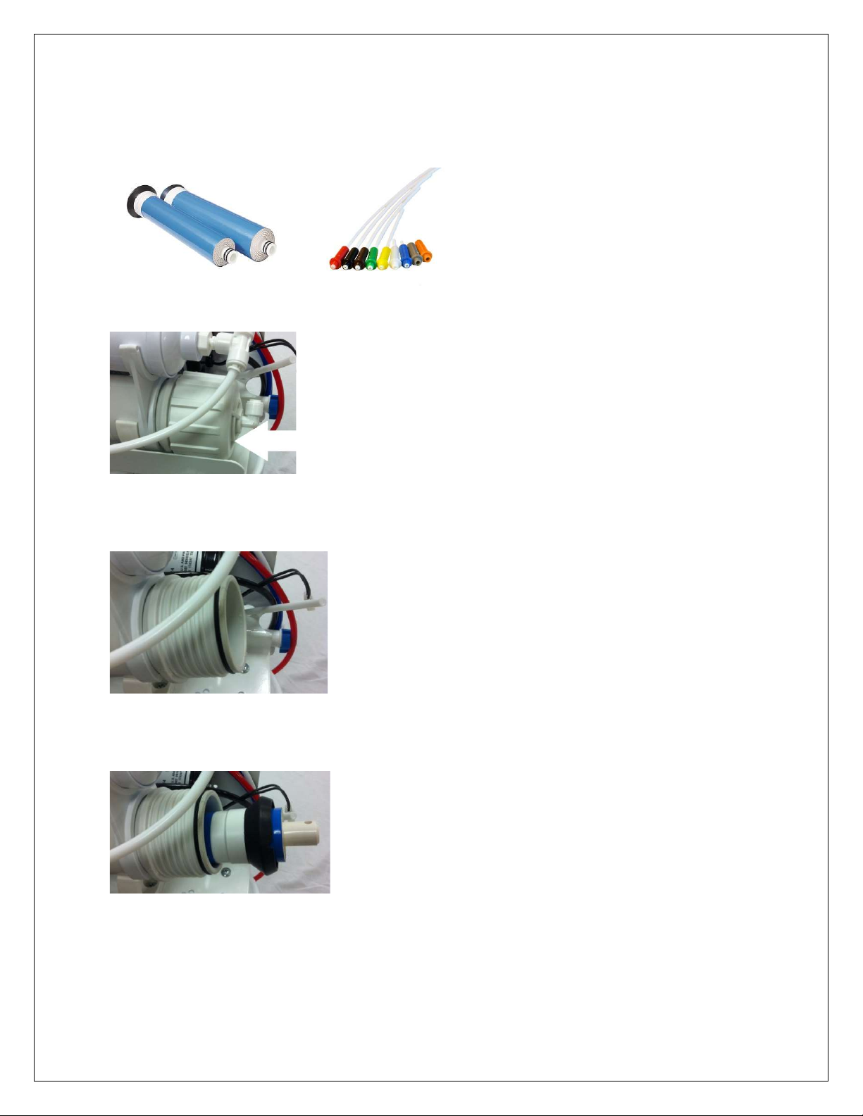
MEMBRANE AND FLOW RESTRICTOR ASSEMBLY PROCESS:
1) Identify membrane element and flow restrictor (color and type depends on membrane
being used) included in box:
2) Identify membrane vessel feed cap:
3) Remove feed cap as shown (turn counter clockwise):
4) Insert membrane in direction as shown:
RF – Series User Manual
MKTF – 167-C 6 05/17

5) Push membrane in as shown:
6) Place feed cap back on as shown (turn clockwise until hand tight):
7) Connect tube to cap as shown:
8) Identify black concentrate (drain) tube:
RF – Series User Manual
MKTF – 167-C 7 05/17

9) Disconnect black tube by following instructions below:
10) Insert flow restrictor in tube:
11) Push in flow restrictor until flush with tube end as shown:
12) Reinsert black tube as shown:
RF – Series User Manual
MKTF – 167-C 8 05/17

1
2
Preparing for Installation
Preparing for installation:
1. This system includes a standard sink top
faucet without an air–gap. In localities where
plumbing codes require installation of an air–
gap, contact your local distributor to obtain a
code approved drain line adapter.
2. The reverse osmosis system may be mounted
to the side of the sink cabinet or set on the
floor of the sink cabinet. It must be positioned
to allow access for service and filter changes.
The assembly should be relatively near the
faucet to maximize flow rate. See Diagram A
for a positioning example.
3. The storage tank should be located where it
can be removed if necessary. The storage
tank may be placed in either the vertical or
horizontal position without affecting the system
performance. If there is insufficient space
under the sink for placement, the tank may be
located in an adjacent cupboard up to 50 ft.
away. See Diagram A for a positioning
example.
4. The faucet should be positioned to allow a free
flow pattern into the sink. It must be positioned
to allow ready access to the mounting
hardware under the sink. See Diagram A for a
positioning example.
RF – Series User Manual
MKTF – 167-C 9 05/17
Diagram A
CAUTION!! Extreme care must be
taken in drilling the hole for the sink–top
faucet. The surface material of most
sinks is extremely hard and brittle and
can be easily chipped or cracked. If you
are uncomfortable performing the
following procedure, it is recommended
that your local distributor be consulted
for techniques and other assistance.
The system’s manufacturer accepts no
responsibility for sink top damage
resulting from system installation.
CAUTION!! Before grinding or drilling,
put on appropriate eye protection (i.e.,
goggles) to protect yourself from
porcelain or metal chips.
CAUTION!! Before grinding or drilling,
ensure that the drill you are using is UL
Laboratories approved and properly
grounded to prevent electrical shock.
DO NOT USE DRILL WHILE USING
OR STANDING IN WATER!!
1. BEFORE DRILLING: Check under the
sink in the area that you plan to install
the faucet and make sure that there is a
flat surface to secure the mounting
hardware. A flat space of approximately
two inches in diameter is needed.
RECOMMENDATION: Before drilling or
grinding mask off the immediate area,
surround the grinding/drilling location,
preferably with duct tape or if duct tape
is unavailable masking tape may be
used. This procedure should help
prevent scratching of the sink surface.
2. Remove everything from inside the sink
and surrounding area. Place paper
towels in the sink to catch the shavings
from the grinding and drilling.
CAUTION!! Porcelain or enamel must
be completely removed in the drilling
Faucet Installation

UP FOR
CONSTANT
FULL FLOW
DOWN FOR
CONTROLLED
MIDDLE POSITION
STAR LOCK WASHER
BRASS INLET NIPPLE
area to prevent immediate dulling of drill
bit.
3. Remove everything from under the sink.
4. Place newspaper or paper towels directly
under drilling location in order to catch the
drill shavings.
5. Using the 1/4” (6mm) drill bit, drill a
centering or pilot hole in the center of the
desired faucet location. Note: this
centering/pilot hole will make it easier for
the 7/16" (11mm) drill bit to cut through the
sink. Operate the drill slowly and carefully
— especially when the drill bit is about to
penetrate the metal. Otherwise, damage to
sink may occur. Use lubricating oil to keep
the drill bit cool while drilling.
6. Discard paper towels and newspaper used
in sink and below sink. Be very careful not
to drop any shavings in sink or on the floor
as they will oxidize and stain surfaces very
quickly.
7. Using a variable speed (VS) drill with a
carbide grinding burr, gently grind away
enough porcelain or enamel to
accommodate the 7/16” (11mm) drill bit,
approximately the size of a dime. Enough
surface material must be removed to
expose the base metal.
HELPFUL HINT: If you notice any rust
spots from dropped shavings you should be
able to get rid of them by scrubbing them
with a cleaning chemical.
8. Cover the drilled hole with your finger. BE
VERY CAREFUL NOT TO CUT
YOURSELF ON SHARP EDGES! Rinse
sink then scrub with cleaner to prevent any
rusting from shavings and to prepare for
faucet installation. Plug hole again while
rinsing off cleaner. Hole must be plugged in
order to avoid water dripping below into
sink cabinet, which may cause damage.
9. Remove faucet from package.
For steps 11–14 refer to Diagram B.
10. Slip the small, thin rubber gasket over the
faucet shank. Next, slip the chrome trim
plate (escutcheon plate) over the faucet
shank. Finally, slip the large, thin rubber
gasket over the faucet shank.
RF – Series User Manual
MKTF – 167-C 10 05/17
11. Take the faucet spigot and insert it into the
faucet base in the hole next to the faucet
handle. Push the faucet spigot in until it
stops.
12. Place the faucet shank through the drill
hole completely, with only the hardware
described in step 11.
13. From under the sink, slip the large, black
plastic locating washer over the faucet
shank. Next, slip the lock washer over the
faucet shank followed by the thin brass
nut.
14. While holding the faucet assembly above
the sink, tighten the thin brass nut below
the sink with an adjustable wrench.
Tighten the brass nut until the faucet
assembly does not move.
CAUTION!! Do not over tighten the brass
nut. Over tightening can cause damage to
the sink or faucet assembly.
Faucet Diagram
BLACK WASHER
CHROME WASHER
RUBBER GASKET
FOR OFF
FLOW
WASHER
BRASS NUT
INLET LINE
COMPRESSION NUT
BRASS SLEEVE
DIAGRAM B

If you have a self
-
piercer assembly
, skip to step # 8.
Self-P
iercer Installation Instructions
3
Installation of Feedwater Adapter
CAUTION!! For your safety and protection, do
not use where water is microbiologically unsafe
or of unknown quality. The water supply to your
system MUST be from the COLD WATER LINE!
Hot water will severely damage your reverse
osmosis system!
Note: In some cases, the supply valve may leak
or may not work at all. If this happens, turn off
the water at the main water shut off for the entire
house. In extreme cases, the house shut off
valve does not work. If this happens, shut the
water off at the street and replace the defective
valves immediately.
Locate the type of shut off valve you have under
your sink and follow that step for connecting the
feedwater.
1. Turn off cold water supply to the sink using
the supply valve located under the sink.
2. Some shut off valves have an extra port for
an icemaker hookup. You will not need the
feed water adapter for this type of installation.
See Diagram C.
3. On some shut off valves, you can install the
feed water adapter directly to the valve. Slip
the black washer into the feedwater adapter.
Tighten feedwater adapter to the valve with
an adjustable wrench. Tighten until snug.
Insert the 1/4” brass straight fitting into the
feed water adapter. TIGHTEN BY HAND
ONLY! DO NOT OVERTIGHTEN!
See Diagram D.
4. Most under sink shut off valves have a built in
smooth or corrugated riser going up to the
faucet. Refer to Diagram E for help with this
type of valve. Secure an adjustable wrench to
the fitting on the cold water side of the sink
faucet – NOT THE REVERSE OSMOSIS
RF – Series User Manual
MKTF – 167-C 11 05/17
FAUCET! Secure another adjustable wrench
to the smooth /corrugated riser line nut.
Gently undo the riser line from the sink
faucet. Do not be alarmed! There will be
water left in the line—this is normal.
However, if the flow does not stop you
probably haven’t shut the water off properly.
(See the Note in Step # 1, Section # 3 if you
need help with water shut off.)
5. Insert the black rubber washer into the
feedwater adapter. Screw the adapter onto
the fitting coming from the cold water side of
the sink faucet. Using two adjustable
wrenches, tighten the feedwater adapter to
the cold water line. Take extreme care not to
twist or damage the connection to the cold
water connection.
CAUTION!! Tightening the connector
improperly to the faucet could cause
irreparable damage to the faucet.
6. Connect the riser from the water shut off
valve to the feedwater adapter. Ensure that
the cone washer on the riser tube is in good
condition. With one adjustable wrench on the
feedwater adapter and another adjustable
wrench on the riser nut, connect the riser to
the feed water adapter.
DO NOT OVER TIGHTEN! This can cause
damage to the riser connection.
7. Insert the 1/4” brass straight fitting into the
feed water adapter. TIGHTEN BY HAND
ONLY! DO NOT OVERTIGHTEN!

Use new cone washer if needed
Connect metal ball valve to the
Insert black washer into bottom
DIAGRAM D
Insert tubing into adaptor for ice maker.
Cold water line
Reversible
Valve handle
Plastic insert
Saddle
back plate
Tightening
screw
Plastic ferrule
Compression nut
Tubing to inlet
Self–piercer valve
NOTE: Self–piercer assembly can only be
installed on smooth riser lines.
8. Clamp the self–piercer onto the riser tube. Fit
the adjustable aluminum bracket to the size of
your riser tube. Then tighten locking nut until
clamp is firmly attached to riser line.
CAUTION!! DO NOT OVER TIGHTEN!! This will
crush the riser tube and destroy it.
9. To pierce the line, simply screw the T–handle
valve clockwise until it stops.
NOTE: If hole in copper tube (cold water line) is
not adequately pierced, this may prevent
sufficient cold water supply to the system and
reduce the performance of reverse osmosis
processing. In this event, open and close the
self–piercing valve several times.
Feedwater Diagrams
DIAGRAM C
feed water connector
of the feed water connector
REMEMBER
TURN OFF WATER FIRST!
Insert black washer into bottom of
the feed water connector
Connect metal ball valve to the
feed water connector
Use new cone washer if needed
RF – Series User Manual
MKTF – 167-C 12 05/17
REMEMBER
TURN OFF WATER FIRST!
DIAGRAM E

4
5
6
Drain Pipe
Installation of Drain Saddle
1. Open the package containing the drain
saddle. See Diagram F.
2. Peel the protective film off of the sponge
gasket. Apply gasket to inside of drain
saddle, using care to align sponge gasket
hole with drain port.
3. Position the drain saddle on the vertical or
horizontal drainpipe from your sink.
Position as far away from the garbage
disposal as possible.
DANGER!! The drain saddle MUST be
installed on the side of the P–trap that goes
to the sink drain! If installed on the wrong
side of the P–trap, sewer gas could enter
the unit and damage it.
4. Drill 1/4” (6mm) hole into the drainpipe.
CAUTION!! Be very careful when drilling into
drainpipe to not drill all the way through—
stop after piercing the first wall of the pipe.
5. Mount the drain saddle. Align the drain
saddle port with the 1/4” drilled hole using a
small drill bit or other small straight object.
6. GENTLY TIGHTEN the two screws evenly
on both sides of the clamp until the clamp
is snug on the pipe.
CAUTION!! To avoid breaking plastic
saddle or crushing drainpipe DO NOT
OVER TIGHTEN!
RF – Series User Manual
MKTF – 167-C 13 05/17
Black Drain
Line
Diagram F
Sponge Gasket
1. Wrap four to five wraps of Teflon tape
2. Hand tighten the plastic shut off ball valve
3. The storage tank should be located where
1. Determine if mounting of the reverse
Positioning the Tank
around the tank threads at the top of the
tank.
to tank stem.
CAUTION!! Hand tighten the valve only!
DO NOT OVERTIGHTEN! If valve is over
tightened it will crack and will leak.
IMPORTANT!! The tank pressure must be
between 8 – 10 PSI when measured
empty. This must be measured with a
good dial or digital pressure gauge. A
pop–up tire gauge will not give you an
accurate reading. If you do not have
access to a good gauge, contact your
local distributor to purchase one.
If your tank pressure is above 10 PSI, use
the tank valve to release pressure until
there is between 8 – 10 PSI. If your tank
pressure is below 8 PSI, use a bicycle
pump to increase pressure between 8 –
10 PSI.
it can be removed if necessary. The
storage tank may be placed in either the
vertical or horizontal position without
affecting the system performance. If there
is insufficient space under the sink for
placement, the tank may be located in an
adjacent cupboard up to 50 feet away.
Reverse Osmosis Unit Placement
and Mounting
osmosis system is necessary or desired.
The system does not need to be mounted
on the wall of the cabinet if there is room
for it to sit on the floor. However, if it is
mounted to the side of the cabinet it is

7
8
easier to change the filters and does not
take up floor space.
IMPORTANT!! Be very careful not to kink any
of the tubing on the reverse osmosis system.
If tubing is kinked, the tubing can rupture and
leak.
2. Position the system on the wall at the desired
mounting location. Using the bracket holes on
the back of the bracket, mark on the wall with
a pencil where the screws need to be
inserted.
3. Set the system aside.
4. Screw the two (2) Phillip head screws
(supplied in the installation packet) into the
wall at the marked positions.
NOTE: Let the screw heads protrude from
the wall enough to hang the reverse osmosis
system safely.
5. Mount the reverse osmosis system onto the
screws.
IMPORTANT!! Be very careful not to kink
any of the tubing on the reverse osmosis
system. If tubing is kinked the tubing can
rupture and leak.
CONNECTING THE FAUCET:
(Blue Line)
1. Connect the blue tubing to the faucet by
slipping the 1/4” brass nut over the tubing
followed by the nylon ferrule.
Note: It is not necessary to have a 1/4” nylon
insert in this line as it would restrict the flow
through the faucet.
2. Push the blue line all the way into the faucet
stem and tighten the brass nut. DO NOT
OVERTIGHTEN!!
Tubing Connections
CONNECTING THE FEEDWATER:
(Red Line)
1. If you installed the feedwater adapter using
step # 3 or # 4 in Section # 3, simply slip a
white 1/4” nylon nut over the red line and
insert the 1/4” nylon insert into the end of the
tubing. Then insert the tubing into the nylon
fitting on the feedwater adapter. Tighten the
nylon nut securely.
DO NOT OVERTIGHTEN!
2. If you have the connection for the icemaker
tee as in Step # 2 of Section # 3 simply slide
the 1/4” brass nut over the red tubing. Slip
the nylon ferrule over the red tubing and
insert the 1/4” nylon insert into the tubing
end. Insert tubing into the cold water shut off
valve and tighten securely.
DO NOT OVERTIGHTEN!
CONNECTING THE TANK:
(White Line)
1. Push in the white tubing and insert it into the
1/4” push pull fitting. Then insert the tubing
into the ball valve on the top of the storage
tank. Tighten securely.
DO NOT OVERTIGHTEN!
CONNECTING THE DRAIN SADDLE LINE:
(Black Line)
1. Slip the 1/4” black nylon nut over the black
tubing and insert into the drain saddle.
Tighten securely. DO NOT OVERTIGHTEN!
Note: It is not necessary to have a 1/4” nylon
insert in this line as there is no pressure on
this line.
1. With all connections complete, turn on the
cold water supply to the reverse osmosis
system.
IMPORTANT!! The Reverse Osmosis Main
Water Shut Off Valve (indicated by the bright
orange tag at the side of the unit) must be
open. This means the blue handle on the
valve must be in line with the red tubing; not
pointing straight up.
2. Immediately check entire reverse osmosis
system and tank for leaks. If you notice any
System Start-Up
RF – Series User Manual
MKTF – 167-C 14 05/17

9
leaks, turn off cold water supply and fix the
leak.
IMPORTANT!! Ensure that the ball valve on
the storage tank is open. This means that the
valve handle is in line with the white tubing.
1. Lift the reverse osmosis faucet handle until it
2. After the tank has filled, open the faucet and
Reverse Osmosis System
locks in the upright position. Let the water
drip for two hours. After 2 hours, turn off the
reverse osmosis faucet. The tank will now fill,
which takes approximately four to five hours.
drain all the water from the tank until it is
empty.
CAUTION!! DO NOT USE FIRST TANK OF
WATER FROM YOUR SYSTEM! The
membrane contains a food grade
preservative to protect it while in storage.
This preservative is not harmful; however, it
does not have a pleasant taste. Therefore, do
not use the first tank of water, which flushes
the entire system removing any preservatives
used during storage and preparing it to
produce quality water.
Flushing the
3. Within two to three hours after draining the
first tank of water, the water is ready for
drinking.
RF – Series User Manual
MKTF – 167-C 15 05/17

Not Enough Water From Holding Tank
Possible Cause
Solution
Low Water Pressure From Dispensing Faucet
Possible Cause
Solution
12
TROUBLESHOOTING
Feedwater valve is plugged or
closed.
Sediment/carbon prefilter or carbon
post filter is clogged.
Low incoming water pressure.
Reverse osmosis membrane is
fouled.
Air pressure in holding tank is
incorrect.
Air bladder in holding tank is
ruptured.
Holding tank valve is closed. Open valve.
No water to drain. Drain flow
restrictor is clogged.
No water to drain. Air gap faucet is
clogged.
Check valve on the reverse
osmosis membrane housing is
stuck.
The automatic shut–off valve is
malfunctioning.
Open valve or unclog.
Replace filters.
Incoming water pressure must be above 40 PSI. Install a booster pump or
permeate pump.
Make sure incoming water pressure is within operating limits. Make sure drain
line is not clogged. (See High TDS) Correct cause of fouling and replace
reverse osmosis membrane.
Empty water from holding tank. Air pressure in valve stem should be between
8 – 10 PSI.
Replace holding tank.
Replace drain flow restrictor.
Clear or replace air gap faucet.
Replace check valve.
Replace automatic shut–off valve.
Air pressure in holding tank is
incorrect.
This is the #1 reason for low flow
from reverse osmosis faucet.
Carbon post filter is clogged. Replace post filter
Holding tank valve is partially
closed.
The faucet is out of adjustment or
faulty.
Heavy water use. Holding tank is
empty.
RF – Series User Manual
MKTF – 167-C 16 05/17
Open faucet and empty water from holding tank. Shut off feedwater to system
and remove holding tank from under sink. (The tank is easier to work on.)
Locate the air valve stem (just like on a car or bicycle tire) and add air. If there
is still water in the tank, continue to add air until all the water is removed.
Once all the water is removed, continue to add air and pressurize to 8 PSI.
Re–install the tank under the sink, turn on the feed supply to the system and
allow the tank to fill.
Open valve.
Repair or replace faucet.
Allow holding tank to refill.

Low Quantity of Water
f
rom Holding Tank
Product Water is High in Total Dissolved Solids (TDS)
Possible Cause
Solution
Tastes and Odors in Product Water
Possible Cause
Solution
High TDS in Product Water
Drain Water Overflows at the Air Gap Faucet
Possible Cause
Solution
Faucet Leaks or Drips
Possible Cause
Solution
Low water production. See section on
Clogged prefilter. Replace filter.
Low incoming water pressure.
Reverse osmosis membrane is not
correctly sealed in membrane housing.
Reverse osmosis membrane is
expended.
Product water and drain water lines are
reversed.
No water to drain. Drain flow restrictor is
clogged.
No water to drain. Air gap faucet is
clogged.
The automatic shut–off valve is not
closing.
New carbon postfilter has not been
rinsed completely.
The incoming feedwater TDS has
increased.
Incoming water pressure must be above 40 PSI. Install a booster pump
or permeate pump.
Check that the reverse osmosis membrane is correctly installed.
If membrane life is unusually short, find and correct the problem.
(Average life is two to three years.) Replace Reverse Osmosis
membrane.
Correct plumbing.
Replace drain flow restrictor.
Clear or replace air gap faucet.
Repair or replace automatic shut–off valve.
Drain holding tank twice to rinse new carbon postfilter.
An increase in feedwater TDS will also give an increase in product water
TDS.
.
Carbon post filter is exhausted. Replace filter.
There is foreign matter in holding tank. Clean, flush and sanitize the holding tank. Replace filters.
Product water and drain water lines are reversed. Correct plumbing.
Dissolved gases in feedwater. Pre–treat feedwater to remove gasses.
Increase in product water TDS. See
Section
Air gap is clogged. Clear air gap
Drain line is clogged. Clear tubing.
Drain flow rate is too high. Replace flow restrictor.
Water leaks from
faucet spout.
Leaks from beneath
the handle.
Adjust faucet by turning the tee bar located under the handle to provide a small amount of
free play in the handle when shut off. Should this not work, repair or replace the faucet.
Repair or replace the faucet.
RF – Series User Manual
MKTF – 167-C 17 05/17

SYSTEM DRAWINGS
RF – Series User Manual
MKTF – 167-C 18 05/17

RF – Series User Manual
MKTF – 167-C 19 05/17

RF – Series User Manual
MKTF – 167-C 20 05/17

SYSTEM WARRANTY
One–Year Limited Warranty
Warranty Terms
Subject to the terms and conditions set forth hereinafter, manufacturer (hereafter “Manufacturer”) warrants to the
original purchaser (hereafter the “Customer”) that the systems and products manufactured by the Manufacturer are
free from defects in material and in workmanship for twelve (12) months from the Warranty Commencement Date
(as defined below) only when used strictly in accordance with the applicable operating instructions and within the
range of the operating conditions specified by the Manufacturer for each such product.
In order to maintain the Manufacturer’s Warranty, an operating log must be maintained and copies will need to be
sent to your local dealer or distributor for review. This Warranty does not extend to systems, equipment, or
components manufactured by others, nor to systems, equipment, or components manufactured by others and
distributed by the Manufacturer. This Warranty does not extend to equipment or components manufactured by
others which have been incorporated into a product by the Manufacturer but, if allowable, the Manufacturer hereby
assigns, without Warranty, to the Customer its interest, if any, under any Warranty made by the Manufacturer of
such equipment or component. This Warranty does not cover disposable items such as fuses, o–rings, regeneration
materials/chemicals, or other such disposable items, which must be replaced periodically under the normal and
foreseeable operating conditions of the goods warranted hereby.
Warranty Commencement Date
The Warranty Commencement Date for each product by the Manufacturer shall be the later of the date of: (1) receipt
by the Customer, or (2) the date of installation at the Customer’s premises provided that such installation must occur
within three (3) months of shipment from the Manufacturer’s manufacturing facility. In no event shall the Warranty
Commencement Date exceed three (3) months from the shipment from Manufacturer’s facility. The Customer shall
provide proof of purchase in order to exercise rights granted under this Warranty. If requested by the Manufacturer,
the Customer must also provide proof of the installation date. Proof of installation shall be returned by Customer to
the Manufacturer within thirty (30) days after installation by virtue of supplying a Warranty Validation Card supplied
with each Manufacturer product fully completed and signed in ink by the Customer and the authorized installer of
the product.
Warranty Service
MANUFACTURER’S OBLIGATION UNDER THIS WARRANTY IS LIMITED TO THE REPAIR OR REPLACEMENT
(AT MANUFACTURER’S SOLE DISCRETION) OF ANY PRODUCT, OR COMPONENT THEREOF, PROVED TO
BE DEFECTIVE IN MATERIAL OR WORKMANSHIP WITHIN THE COVERED WARRANTY PERIOD.
The Customer, at the Customer’s risk and expense, shall be responsible for returning such product or component,
only after obtaining a Return Goods Authorization (RGA) number from the Manufacturer, arranging for freight
prepaid, and in conformance with any special packaging and shipping instructions set forth on the operation
documentation or RGA instructions, or as otherwise reasonably required, to Manufacturer’s address, together with
(1) RGA number issued by the Manufacturer at Customer’s request; (2) proof of purchase and, if necessary, proof
of installation date; (3) a Return Goods Authorization Form; (4) a description of the suspected defects; (5) the serial
number of the Manufacturer product alleged to be defective; and (6) a description of the type of water and
pretreatment equipment which has been utilized in connection with the product, if any; (7) an operating log, which
can be found in the product manual. Manufacturer shall, in Manufacturer’s reasonable discretion, be the sole judge
of whether a returned product or component is defective in material or workmanship.
RF – Series User Manual
MKTF – 167-C 21 05/17

Required or replaced products or components shall be returned surface freight. In genuine emergency situations,
Manufacturer will at Manufacturer’s sole discretion) forward replacement parts to Customer without waiting for
authorized return of the questionable part(s). In such cases, Customer will issue a purchase order or other payment
guarantee prior to shipment. If the returned part is found to have been misused or abused, or the defective part is
not received by Manufacturer within thirty (30) days; the Customer will be invoiced for the replacement part(s)
provided. This Warranty does not cover or include labor and/or travel to the Customer’s premise or location or any
other location. Charges of $1000 per day plus associated travel expenses will be incurred by the Customer in
providing the Warranty Service at any location other than Manufacturer’s main headquarters; that is if the
Manufacturer deems that the product is not covered by said Warranty. The Manufacturer reserves the right to
precondition such travel to Customer’s premises upon prepayment of Manufacturer’s anticipated costs of attending
such premises.
Voidability of Warranty
This Warranty shall be void and unenforceable as to any Manufacturer product which has been damaged by
accident, mishandling, abuse or has been repaired, modified, altered, disassembled or otherwise tampered with by
anyone other than Manufacturer or an authorized Manufacturer service representative; or, if any replacement parts
are not authorized by Manufacturer have been used, or, the product has not been installed, operated and maintained
in strict accordance and adherence with the operating documentation and manuals for such product. Any expressed
Warranty, or similar representation of performance set forth in the operation documentation for media or resin
incorporated into a product by the Manufacturer shall be void and unenforceable unless the feed water requirements
set forth in the operating documentation for such product are unequivocally and strictly adhered to.
Limitations and Exclusions
THIS WARRANTY AND REMEDIES DESCRIBED HEREIN AND HEREINABOVE ARE EXCLUSIVE AND IN LIEU
OF ANY AND ALL OTHER WARRANTY OR REMEDIES, EXPRESSED OR IMPLIED, INCLUDING WITHOUT
LIMITATION, ANY IMPLIED WARRANTY OF MERCHANTABILITY OR FITNESS FOR A PARTICULAR
PURPOSE. IN NO EVENT SHALL THE MANUFACTURER BE LIABLE FOR ANY CONSEQUENTIAL,
INCIDENTAL OR OTHER SIMILAR TYPES OF DAMAGES, FOR DAMAGES FOR THE LOSS OF PRODUCTION
OR PROFITS, OR INJURY TO PERSON OR PROPERTY. NO PERSON HAS ANY AUTHORITY TO BIND THE
MANUFACTURER TO OTHER THAN WHAT IS SET FORTH ABOVE.
THIS WARRANTY GIVES THE CUSTOMER SPECIFIC LEGAL RIGHTS AND THE CUSTOMER MAY ALSO HAVE
OTHER RIGHTS WHICH VARY FROM JURISDICTION TO JURISDICTION. THE PARTIES RECOGNIZE AND
AGREE, THAT IN ALL RESPECTS THE LAWS OF THE STATE OF CALIFORNIA SHALL APPLY TO AND SHALL
GOVERN ANY INTERPRETATION OR LEGAL SIGNIFICANCE OF THIS DOCUMENT.
NO WARRANTY OR OTHER LIABILITY OF THE MANUFACTURER TO CUSTOMER UNDER THIS AGREEMENT
OR OTHERWISE WILL IN ANY EVENT EXCEED THE COST OF REPLACEMENT OF THE APPLICABLE
MANUFACTURER PRODUCT, PART, OR ACCESSORY THAT IS SUBJECT TO ANY BREACH OF
MANUFACTURER’S WARRANTY. MANUFACTURER WILL NOT BE LIABLE FOR ANY DAMAGE TO ANY
PROPERTY OF CUSTOMER OR TO CUSTOMER’S CUSTOMERS FOR ANY CONSEQUENTIAL, INCIDENTAL,
OR ECONOMIC LOSS OR COMMERCIAL DAMAGE WHATSOEVER. REMEDIES HEREIN PROVIDED ARE
EXPRESSLY MADE THE SOLE AND EXCLUSIVE REMEDIES FOR BREACH OF ANY WARRANTY OR OTHER
OBLIGATION HEREUNDER EXPRESS OR IMPLIED OR FROM THE OPERATION OF LAW.
RF – Series User Manual
MKTF – 167-C 22 05/17
 Loading...