


TUBE HEATER
TROUBLESHOOTING GUIDE
MODELS: DX, DX-2 & XTS
THESE HEATERS MUST BE INSTALLED AND SERVICED BY TRAINED GAS
INSTALLATION AND SERVICE PERSONNEL ONLY. READ AND UNDERSTAND ALL
INSTRUCTIONS THOROUGHLY BEFORE ATTEMPTING TO INSTALL, OPERATE OR
SER VICE THE DETROIT RADIANT PRODUCTS COMP ANY HEATER. FAILURE TO COMPLY
WITH THESE WARNINGS AND INSTRUCTIONS, AND THOSE ON THE HEATER, COULD
RESULT IN PERSONAL INJURY, DEATH, FIRE, ASPHYXIATION AND/OR PROPERTY
DAMAGE. RETAIN THESE INSTRUCTIONS FOR FUTURE REFERENCE.
CAUTION! Heater may be hot. Do not store or use gasoline or other flammable vapors and
liquids in the vicinity of this or any other appliance. Note presence of flammable gas and
electrical shock hazard.
WARNING! Extinguish open flame while servicing heaters. Test for gas leaks with soap and
water solution only. Wear safety glasses while servicing unit.
FOR YOUR SAFETY!
IF YOU SMELL GAS:
1. Open windows.
2. Do not touch electrical switches.
3. Extinguish any open flame.
4. Immediately call your gas supplier.
Approval Standards and Certifications
Detroit Radiant Products units comply with or are certified by the following Organizations or
Standards:
- American National Standards (ANSI Z83.6)
- Occupational Safety and Health Act (OSHA)
- American Gas Association (AGA)
- International Approval Services (IAS)
IMPORTANT: Any alteration of the system or of the factory-authorized components specified
either in this manual or by Detroit Radiant Products Company voids all certification and warranties.
SHUTDOWN INSTRUCTIONS!
1. Open electrical circuit.
2. Rotate heater’s manual gas valve
knob to “OFF” position.
Detroit Radiant Products Company
21400 Hoover Road • Warren • Michigan • 48089 • (586) 756-0950 • Fax: (586) 756-2626
http://www .reverberray.com email: sales@detr oitradiant.com

Tools Recommended to Troubleshoot Heaters
-Digital Multimeter - Used for troubleshooting & testing electrical circuits.
(Part 1A783 from Grainger)
-Flame Rectification Meter - Used for testing rectification of flame with the digital multimeter.
(Channel Products)
-Digital Manometer Kit - Used for taking gas pressure, digitally.
(Part 100281-21 from Dwyer Instruments)
-Liquid Manometer Kit - Used for taking gas pressure, via a liquid manometer.
(Part 115010-00 from Dwyer Instruments)
-Digital Hygro-Thermometer (Amprobe #TH-2) - Reads temperature from -10 to 50
(Part 1P124 from Grainger)
-Incline Manometer - Used for measuring pressure inside burner box. Provides data for pressure switch.
(Cat# 172 from Dwyer Instruments)
-1/4” Nut Driver - Can be used to remove screws holding top on.
(Part 5X509 from Grainger)
O
C and relative humidity from 5-95%.
-Pliers 8” - Tool for burner box access.
(Part 6C183 from Grainger)
-Pipe Wrench 8” - Can be used to disassemble gas train assembly.
(Part 4A497 from Grainger)
-Ratcheting Box Wrench - Can be used to remove orifice and bolts. (size 7/16” and 3/8”)
(Part 1AMW9 from Grainger)
-6” Steel Rule - Used for measuring air orifice size.
(Part 6C289 from Grainger)
-Terminals 1/4” Female - Extra female spade terminals.
-Barb Fitting - Fitting to take gas pressure at the valve.
-Vinyl Tubing - Tubing for pressure measurements. (size 5/16” x 3’)
-Jumpers/Connectors - Used to jump out the pressure switches.
-Self Tapping Screws - Extra Screws.
-Drill Bits 1-60, A-Z - Drill Bits 1-60, A-Z, for measuring gas orifice size (DMS).
-Manuals - DX, DX-2 or XTS Series Installation, Operation & Maintenance manuals (IOM’s).
1

Theory of Operation
Starting Circuit
When voltage is applied to L1 and L2, a circuit is completed from L1 via the blower motor to L2. The
blower fan is mounted in the control box and rated to supply sufficient air combustion.
Air pressure generated by the blower will cause the normally open burner pressure switch No. 1 to close.
Another circuit is completed from L1 to the hot surface ignition control and back to L2. There is a five
second delay , then the glo-bar is powered. After the glo-bar has been powered for 45 seconds, the control
causes the gas valve to open and initiates the ignition trial. Power to the glo-bar is shut off during the last
two or three seconds of the ignition trial.
Running Circuit
After ignition, the flame rod monitors the flame. As long as a flame is present, the valve is held open. If the
flame is lost, the control acts to close the valve within one second, and a new trial sequence identical to that
at start-up is initiated. If proof of flame is not established within 8.5 seconds, the unit will lock out. If
lockout occurs, the control can reset by briefly interrupting the power source.
Note: The DX-2 Series heaters have added indicator lights to assist in troubleshooting and ignition sequence.
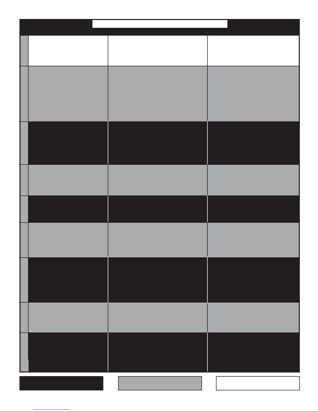
DX/XTS Series Heaters
DX-2 Series Heaters
2

must be replaced.
The fan is faulty and
YES
connections.
Repair wiring or hose
WARNING: Bypassing any switch
is for testing purposes only. Do not
leave switch bypassed during normal
operation or heater’s built-in safety
mechanisms will be compromised.
*
Replace the switch after verifying the
following:
* Baffle(s) is in the tube(s) farthest
from the burner.
* Heater, fan blower, squirrel cage,
intake and exhaust are clean and free
from dirt and obstructions.
* The 4” air intake pipe does not
exceed 20 feet and/or 2 elbows.
* There is not a negative pressure
experienced at the area of air intake
(i.e. attic space, high-winds, very tight
building).
please address the problem.
If any of the previous were occurring,
Is there 120V
NO
Is the blower
YES
Is the power at the
DX & XTS Troubleshooting Flow Chart (models w/out indicator lights)
NO
NO
coming to the fan?
obstructed?
NO
heater 120V?
Correct wiring.
YES
& lubricate fan.
Remove obstruction
electrical problem.
Find the source of the
NONO
Replace ignitor.
Is the resistance through the
YES
Is the ignitor
physically damaged?
NO
NO
YES
Are they ok?
ignitor 45-400S?
Check for loose wiring or restrictions in
hose connections to the pressure switch.
YES
120V?
ignition sequence (usually 30-45
Check voltage at ignitor during the
seconds after power to heater). Is it
NO
NO
YES
Is the inlet or the outlet of the unit
obstructed? I.e. ice, birds nest, dirt, etc.
YES
*
glow red?
switch, one at a time. (Be sure to
The heater is equipped with 2 safety
the blower compartment is a normally
pressure switches. The burner switch in
Remove obstruction.
closed switch. Temporarily place
jumpers across the terminals of each
open switch and the exhaust switch in
the gas valve compartment is a normally
NO
for 120V going from switch to
both pressure switches and check
T emporarily place jumpers across
reinstall the cover.) Does the ignitor
YES
circuit board. (Be sure to
entering the circuit board?
reinstall the cover.) Is there 120V
NO
*
Replace circuit board.
or replace wiring.
Faulty wiring. Repair
YES
Does the fan
Turn up Thermostat
blower turn on?
YES
Does the ignitor
warm up and glow red?
3

only?
NO
YES
circuit board.
Check to make sure
flame sensor wire is
OK and then replace
than 30 Volts DC?
With voltmeter, check DC
NO
voltage at flame rod. Is it greater
Possibly, the circuit
should be replaced.
board and/or wiring
harness is faulty . These
NO
Correct
problem.
NO
Replace
gas valve.
YES
and flame rod sensor located next to the glo-
bar. Other models have a glo-bar ignitor only,
Correct
problem.
NO
purged of air.
Certain models have a separate glo-bar ignitor
Make sure gas lines were
YES
which acts as both an ignitor and flame sensor.
YES
Is the heater properly grounded?
within minimum and maximum
Check to make sure gas pressure is
rating label. Is gas pressure OK?
inputs, as indicated on AGA burner
YES
YES
weak. Check to make sure
YES
Sensing rod is faulty or flame is
Does model in question have glo-bar ignitor
proper parts.
Consult factory for
Correct
problem.
NO
NO
Correct problem.
Is the heater’s polarity correct?
NO
YES
burner rating label and then
replace sensing rod if needed.
pressure as indicated on AGA
heater is operating at proper gas
exhaust.
switch may be
Exhaust pressure
restriction in the
faulty or there is a
YES
YES
120V to valve?
during valve opening
Test for 120V at valve
YES
After ignitor is
the heater). Is there
period (usually 30-45
seconds after power to
NO
YES
valve open?
within minimum and maximum
Check to make sure gas pressure is
rating label. Is gas pressure OK?
inputs, as indicated on AGA burner
warmed up, does gas
an ON position?
Is the gas cock in
NO
YES
light?
Does the burner
4
Does the burner
come on and then
shut off?
approx. 8 seconds and then
Does the burner stay on for
NO
NO
YES
stay on?
Does the burner
call for heat ends?
Does heater stay on until
(1 or 2 seconds).
turn off immediately
Check to make sure that the pressure
* High winds
heater to shut down:
* Improper grounding
The following can cause the
* Taking combustion air from
YES
rating label. Is gas pressure OK?
is within minimum and maximum
inputs as indicated on the AGA burner
the attic
* Dirty environment
* Fluctuating gas pressure
* Baffle not located properly
Troubleshooting ends.

NO
Replace burned out light.
YES
must be replaced.
The fan is faulty and
YES
NO
Is there 120V
coming to the fan?
NO
obstructed?
Is the blower
Correct wiring.
YES
& lubricate fan.
Remove obstruction
Does the light energize?
Replace the switch after verifying the
following:
* Baffle(s) is in the tube(s) farthest
from the burner.
switches. The burner switch in the blower
The heater is equipped with 2 safety pressure
compartment is a normally open switch and the
jumpers across the terminals of each switch,
a normally closed switch. Temporarily place
exhaust switch in the gas valve compartment is
one at a time. (Be sure to reinstall the cover.)
*
YES
YES
Repair wiring.
Check for loose wiring or
pressure switch. Are they ok?
resistance in hose connection to
NO
ignitor 45-400S.
Is resistance through the
YES
(usually 30-45 seconds
Check voltage at ignitor
during ignition sequence
please address the problem.
* Heater, fan blower , squirrel cage,
intake and exhaust are clean and free
from dirt and obstructions.
* The 4” air intake pipe does not
exceed 20 feet and/or 2 elbows.
* There is not a negative pressure
experienced at the area of air intake
(i.e. attic space, high-winds, very tight
NO
Replace ignitor.
NO
after power to the
heater). Is it 120V?
Replace circuit board.
If any of the previous were occurring,
building).
be faulty and need to be replaced.
The circuit board &/or wiring harness may
WARNING: Bypassing any switch
is for testing purposes only. Do not
leave switch bypassed during normal
operation or heater’s built-in safety
*
Replace faulty light.
Replace valve.
Correct problem.
NO
YES
mechanisms will be compromised.
YES
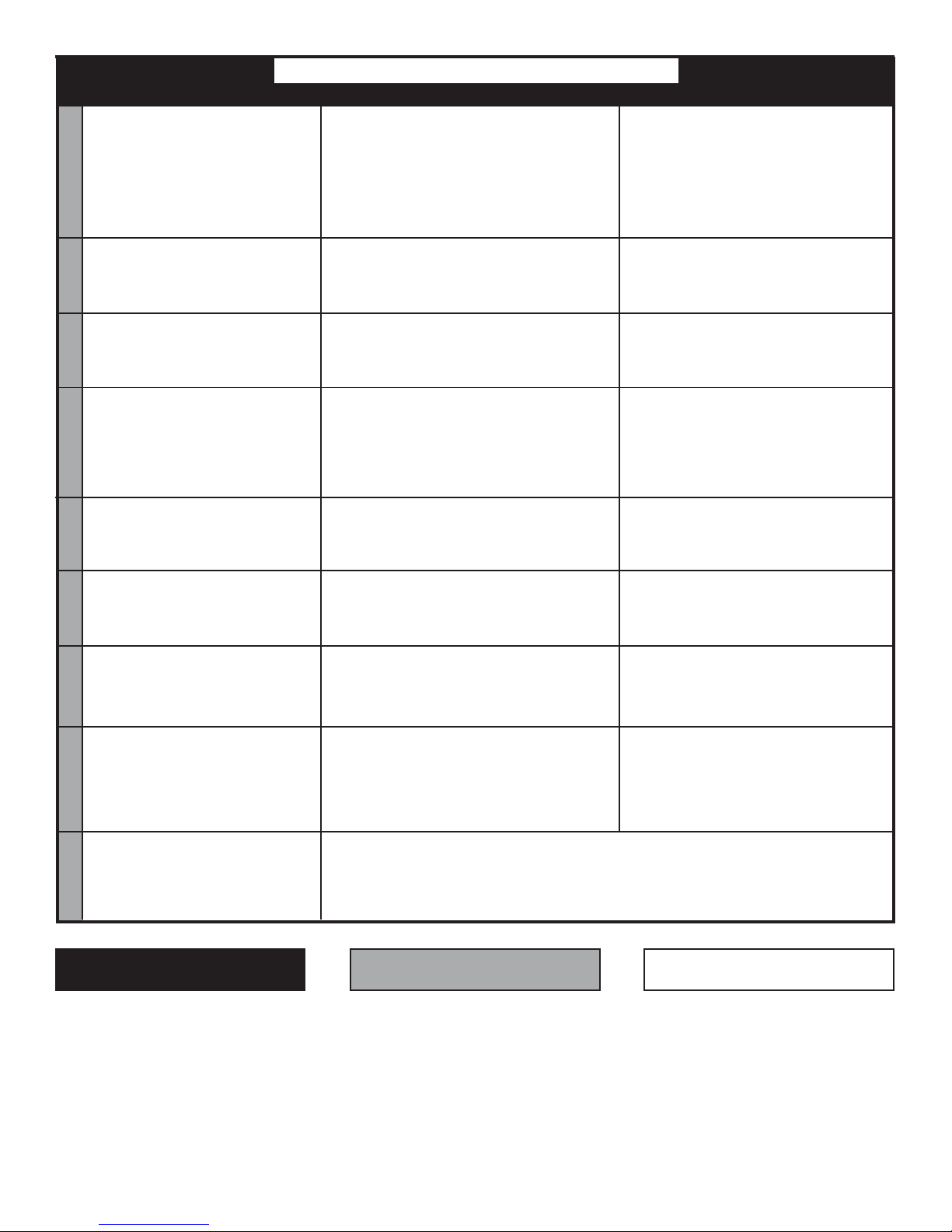
DX-2 Troubleshooting Flow Chart (models with indicator lights)
Turn up Thermostat
NO
heater 120V?
Is the power at the
NO
turn on?
Does the fan
electrical problem.
Find the source of the
NO
Is the light
YES
YES
of the unit obstructed
Is the inlet or the outlet
(i.e. ice, birds nest, dirt)?
Remove obstruction.
so, replace.
burnt out? If
NO
YES
light energize?
Does the switch
NO
damaged?
Is the ignitor physically
NO
up and glow red?
Does the ignitor warm
5
YES
YES
NO
YES
ok?
all?
Replace ignitor.
Does burner ignite at
NO
YES
come on?
Does valve light
min. & max. inputs as indicated on
AGA burner rating label. Are both
Check to make sure pressure is within
NO
Does valve open?

only?
NO
YES
circuit board.
ok and then replace
Check to make sure
flame sensor wire is
than 30 Volts DC?
With voltmeter, check DC
NO
voltage at flame rod. Is it greater
Possibly , the circuit
should be replaced.
board and/or wiring
harness is faulty . These
NO
120V to valve?
during valve opening
Test for 120V at valve
the heater). Is there
period (usually 30-45
seconds after power to
YES
Correct
problem.
NO
Replace
gas valve.
YES
and flame rod sensor located next to the glo-
bar. Other models have a glo-bar ignitor only,
Correct
problem.
NO
purged of air.
Certain models have a separate glo-bar ignitor
Make sure gas lines were
YES
which acts as both an ignitor and flame sensor.
YES
Is the heater properly grounded?
within minimum and maximum
Check to make sure gas pressure is
rating label. Is gas pressure ok?
inputs, as indicated on AGA burner
YES
YES
an ON position?
Is the gas cock in
Does the burner stay on for
approx. 8 seconds and then
weak. Check to make sure
YES
Sensing rod is faulty or flame is
Does model in question have glo-bar ignitor
proper parts.
Consult factory for
Correct
NO
Exhaust pressure
problem.
NO
Correct problem.
Is the heater’s polarity correct?
NO
Does the burner
come on and then
turn off immediately
YES
(1 or 2 seconds).
Check to make sure that the pressure
is within minimum and maximum
shut off?
burner rating label and then
replace sensing rod if needed.
pressure as indicated on AGA
heater is operating at proper gas
exhaust.
switch may be
restriction in the
faulty or there is a
YES
rating label. Is gas pressure ok?
inputs as indicated on the AGA burner
YES
NO
YES
valve open?
After ignitor is
within minimum and maximum
Check to make sure gas pressure is
rating label. Is gas pressure ok?
inputs, as indicated on AGA burner
warmed up, does gas
NO
YES
ignite?
Does the burner
6
NO
YES
stay on?
Does the burner
NO
heater to shut down:
* Improper grounding
The following can cause the
call for heat ends?
YES
Does heater stay on until
the attic
* High winds
* Dirty environment
* Fluctuating gas pressure
* Taking combustion air from
* Baffle not located properly
Troubleshooting ends.

DX & XTS
Series Heater
DX-2
Series
Flame Rod
Heater
Burner
Fan
Burner Pressure Switch
Exhaust Pressure Switch
Glo-Bar Ignitor
Glo-Bar Cover
Circuit Board
Flame Rod
Gas Valve
Exhaust Pressure Switch
Glo-Bar Ignitor
Burner Pressure Switch
Circuit Board
Gas Valve Indicator Light
Pressure Switches Indicator Light
Fan
Glo-Bar Cover
Burner
Gas Valve
7

PICTURE 1
PICTURE 3PICTURE 2
Burner Pressure Switch
PICTURE 4
12
1) 125M-200M - Natural or Propane
2) 100M & below - Natural
3) 100M & below - Propane
3
Gas Burners
Circuit Board
PICTURE 6PICTURE 5
Exhaust Pressure Switch
PICTURE 7
Glo-Bar & Flame Rod
Fan
Air Intake Collar & Orifice
Manifold Tap
w/ Barb fitting
inserted
Gas Valve
PICTURE 9PICTURE 8
Gas Valve
Pressure Switches
Switch & Valve Indicator Lights
This symbol appears when directions indicate the presence of flammable gas.
This symbol appears when directions indicate the presence an electrical shock hazard.
8
GENERAL TROUBLESHOOTING CHART
SYMPTOM EXPLANATION SOLUTION
Thermostat closed, fan does not
operate.
Page 11
1. Blown fuse.
2. Faulty thermostat.
3. Loose or disconnected wire.
4. Faulty fan.
1. Replace.
2. Replace.
3. Repair as required.
4. Lubricate, repair or replace.
1
Thermostat closed. Fan operates.
No glo-bar energization.
Page 12-13Page 12-13Page 14Page 14Page 15Page 15Page 16
Thermostat Closed. Fan operates.
No Switch Lights.
Note: If Glo-Bar is energized, the
switch light is faulty.
Thermostat closed. Fan and glo-bar
operate. After 45 second glo-bar
shuts off. No ignition.
Thermostat closed, fan operates.
Switch light is energized. No globar energization.
1. Loose or disconnected wire.
2. Box lid or gasket not in place.
3. Plugged pressure switch lines.
4. Plugged inlet or restricted exhaust vent.
5. Baffle location incorrect.
6. Faulty pressure switches.
7. Faulty circuit control.
8. Faulty glo-bar.
1. Loose or disconnected wire.
2. Box lid or gasket not in place.
3. Plugged pressure switch lines.
4. Plugged inlet or restricted exhaust vent.
5. Baffle location incorrect.
6. Faulty pressure switches.
1. Closed gas supply .
2. Dirty or restricted gas orifice.
3. Faulty valve. Disconnected valve wire.
4. Inlet pressure too high - (max pressure = 14”).
1. Faulty glo-bar.
2. Faulty circuit control.
1. Repair as required.
2. Put in place.
3. Clean as necessary .
4. Remove foreign matter.
5. Reposition baffle.
6. Replace only - do not adjust.
7. Replace circuit control.
8. Replace glo-bar.
1. Repair as required.
2. Put in place.
3. Clean as necessary .
4. Remove foreign matter.
5. Reposition baffle.
6. Replace only - Do not adjust.
1. Open all gas connections.
2. Remove and clean with a soft cloth.
3. Replace valve or reconnect wires.
4. Adjust pressure.
1. Replace.
2. Replace.
2
2
3
3
Thermostat closed. Fan and globar operate. Ignition occurs.
Burner cycles off and will not
recycle.
Thermostat closed, fan operates.
Switch light is energized. Glo-Bar
is energized. No Valve light.
Note: If heater fires, the valve light
is faulty .
Thermostat closed. Fan and globar operate. Ignition occurs.
Burner cycles off. Burner recycles.
Thermostat closed, fan operates.
Switch light, Glo-Bar and Valve
light is energized. After 45
seconds, glo-bar shuts off. No
Page 16
Ignition.
1. Polarity reversed.
2. No electrical ground.
3. Faulty circuit control.
4. Low gas pressure.
5. Flame rod faulty .
1. Disconnected valve wire.
2. Faulty circuit control.
1. Low gas pressure.
2. Baffle improperly positioned.
3. Faulty exhaust pressure switch.
4. Restricted flue vent.
1. Closed gas supply .
2. Dirty or restricted gas orifice.
3. Faulty valve or disconnected wires.
4. Inlet pressure too high (max. pressure = 14”).
1. Correct polarity.
2. Connect electrical ground with junction box.
3. Replace.
4. Provide required gas pressure.
5. Replace.
1. Reconnect wire.
2. Replace circuit control.
1. Provide required gas pressure.
2. Reposition baffle.
3. Replace.
4. Remove foreign matter.
1. Open all gas connections.
2. Remove and clean with a soft cloth.
3. Replace valve or reconnect wires.
4. Lower inlet pressure.
4
4
5
5
Refers to DX-2 Series Heaters
with Indicator Lights
Refers to DX or XTS Series Heaters
without Indicator Lights
9
Refers to all Heaters
GENERAL TROUBLESHOOTING CHART
SYMPTOM EXPLANATION SOLUTION
Loss of heater efficiency .
Page 16
Radiant tube leaking burnt gases.
Page 17Page 17Page 17Page 18
Condensation.
Tube bowing.
Tube corroding.
Page 17
1. Low gas pressure.
2. Dirty or restricted orifice.
3. Foreign matter inside burner assembly.
4. Reflector is sooted and has lost its
reflective ability .
5. Clogged fan blower.
1. Loose tube connections.
2. Holes or cracks in radiant tubes.
1. Stack length too long.
2. Light gauge flue stack used.
3. Contaminated combustion air.
1. Insufficient combustion air .
2. Contaminated combustion air.
3. Overfired.
4. Heater’s tubes are unable to expand.
1. Contaminated combustion air.
1. Provide required gas pressure.
2. Remove and clean with a soft cloth.
3. Clean as necessary .
4. Clean with aluminum cleaner and
soft cloth.
5. Clean.
1. Assure that tube is fully inserted into
flared end and properly clamped.
2. Replace.
1. Shorten stack.
2. Minimum of 26 gauge vent pipe is required.
3. Provide fresh air inlet duct.
1. Provide 2 sq. in. of free air per
5000 BTU/H of input.
2. Provide fresh air inlet duct.
3. Check gas pressure and orifice size.
4. Remount heater with 16” section of flex.
1. Provide fresh air inlet duct.
6
7
8
9
10
Visual inspection of burner
operation not possible.
Page 18
Stack sooting.
Odor or fumes in space.
Page 18
“How To” Instructions
Page 19
Refers to DX-2 Series Heaters
with Indicator Lights
1. Dirty or sooted sight glass.
2. Unit mounted upside down.
1. Insufficient combustion air .
2. Improper gas.
1. Vaporized solvents decomposing when
contacting radiant tubes.
2. Evaporation of oils/solvents at floor level.
3. Fork lifts.
4. Loose tube connections.
inlet pressure, manifold reading, proper polarity,
positive ground, negative pressure, bypass pressure switches
1. Remove and clean or replace.
2. Mount correctly.
1. Provide 1 sq. in. of free air for every
5000 BTU/H of input.
2. Correct with proper gas input.
1. Address ventilation concerns.
2. Address ventilation concerns.
3. Address ventilation concerns/repair.
4. Tighten tube clamps to 50-100 ft. lb.
Refers to DX or XTS Series Heaters
without Indicator Lights
11
12
13
Refers to all Heaters
10

1 - Thermostat Closed, Fan Does Not Operate
If the thermostat is closed (on) and heater does not operate, check the following:
1.1
Check the building’s main circuit breaker or fuse box. The problem may be a blown fuse or circuit.
1.2
Thermostat Operation: Verify the thermostat is allowing power to be sent to the heater. Confirm by
measuring the voltage to the heater using a volt meter (See picture below). If there is no power , the
problem is in the thermostat and it should be replaced. If power is at the heater, continue on to the
next step.
1.3
Check the electrical connections leading to the fan. Be sure that the wire nuts are tight.
1.4
Using the voltmeter, check to be sure power is going to the fan (pg. 8, pic. 5). If there is power , try
cleaning and oiling (SAE-20 oil) the motor. If fan still not working, it is faulty.
2 x 4 Junction Box
Refer to warnings on cover prior to servicing the unit. Bypass safety pressur e switches for supervised troubleshooting purposes only.
*Do not leave switches bypassed while the heater is unattended or for normal operations.
Consult Detroit Radiant Products for further technical information
Picture 1.2
11

2 - Thermostat Closed, Fan Operates, No Glo-Bar Energization
(This step is applicable for all models)
2.1
Locate any disconnected or loose wires and repair.
2.2
The normally open Burner Pressure Switch is located on the fan side of the heater (pg. 8, pic. 1 ). This switch
must be closed before the glo-bar can be energized. *Bypass this switch (pg. 19, #6) to check for proper function.
Once bypassed, reinstall the cover and test the heater. If it works, there is a problem with the burner pressure
switch or what it is sensing, and you should continue with step 2.2.1. If bypassing this pressure switch does not
make the heater work, continue with step 2.3.
2.2.1
Be sure lid is on correctly and gasket is intact.
2.2.2
Make sure the clear vinyl tube that bleeds pressure to the outside of the heater is clean and clear of
obstructions.
2.2.3
Make sure the heater’s vent cap is in place and in good condition. Also, check for obstructions within the
cap.
NOTE: Excessive winds may cause properly operating safety pressure switches to shut down the heater. Heaters ducted through (on either the
intake or exhaust sides) the roof may be deprived of the air necessary to pressurize the burner box. This “chimney effect” will typically not
allow the burner pressure switch to close. Heaters vented through a sidewall may see too much back-pressure, thus opening the exhaust
pressure switch. In either case, the caps need to be shielded to lessen the effects of high winds.
2.2.4
Make sure the heater’s baffle is located properly. It should be found at the exhaust end of the emitter tube.
2.2.5
The fan may not be accurately pressurizing the heater. Clean obstructions from the air -intake pipe and cap
(pg. 8, pic. 8). Clean the squirrel cage. Oil the motor (SAE-20). Examine and clean the fan blades
(pg. 8, pic. 5). Once the fan is completely clean, retry the heater, without bypassing the Burner Pressure
Switch. If the glo-bar is still not energizing, continue with Step 2.2.6.
2.2.6
If steps 2.2.1 - 2.2.4 were performed and the heater still won’t properly function, the burner pressure switch
is faulty .
Refer to warnings on cover prior to servicing the unit. Bypass safety pressur e switches for supervised troubleshooting purposes only.
*Do not leave switches bypassed while the heater is unattended or for normal operations.
Consult Detroit Radiant Products for further technical information
12

2 - Thermostat Closed, Fan Operates, No Glo-Bar Energization (cont.)
(This step is applicable for all models)
2.3
The Exhaust Pressure Switch is located on the valve side of the heater (pg. 8, pic. 4). *Bypass this switch
(pg. 19, #6). If the heater works with the exhaust pressure switch bypassed, the problem is with this switch or what
it is sensing and you should continue with step 2.3.1. If bypassing this switch does not cause the heater to work,
continue with step 2.4.
2.3.1
Be sure the lid is on correctly and tightly and the gasket is in intact.
2.3.2
Check to make sure the clear vinyl tube that bleeds pressure to the outside of the heater is clean and clear of
obstructions.
2.3.3
Clean any obstructions from the emitter tube, exhaust tube and vent cap.
2.3.4
Check to make sure the heater’s baffle is located properly. It should be found at the exhaust end of the
emitter tube.
NOTE: Excessive winds may cause properly operating safety pressure switches to shut down the heater. Heaters ducted through (on either the
intake or exhaust sides) the roof may be deprived of the air necessary to pressurize the burner box. This “chimney effect” will typically not
allow the burner pressure switch to close. Heaters vented through a sidewall may see too much back-pressure, thus opening the exhaust
pressure switch. In either case, the caps need to be shielded to lessen the effects of high winds.
2.3.5
If steps 2.3.1 - 2.3.4 were performed and the heater still won’t properly function, the exhaust pressure
switch is faulty .
2.4 (This step is applicable for DX & XTS models only)
Check the Circuit Board (pg. 8, pic. 3). Use a volt meter to ensure that power is actually entering the circuit
board. Turn of f the gas to the heater and *bypass both pressure switches (pg. 19, #6), as a heater with no cover will
not allow pressure switches to function properly. 120 volts exiting the circuit board indicates that the glo-bar is
faulty. If no voltage exits the circuit board, it is faulty.
Refer to warnings on cover prior to servicing the unit. Bypass safety pressur e switches for supervised troubleshooting purposes only.
*Do not leave switches bypassed while the heater is unattended or for normal operations.
Consult Detroit Radiant Products for further technical information
13

3 - Thermostat Closed, Fan & Glo-Bar Operate.
After 45 Seconds Glo-Bar Shuts Off, No Ignition.
(This step is applicable for DX & XTS models only)
3.1
Be sure that the gas valves inside and outside of the heater are turned to the ON position.
3.2
Locate and confirm that the gas orifice is not plugged with dirt, spider webs or rust.
3.3
Turn off the gas to the heater and *bypass both the Burner & Exhaust Pressure Switches (pg. 19, #6). Test
the voltage coming from the Circuit Board to the Gas Valve (pg. 8, pic. 6) using a volt meter. If there is 120
volts, the gas valve is faulty. If there is less than 102 volts or no voltage at all, the circuit board is faulty.
3.4
The inlet pressure entering the system may be too high. The maximum value for both natural and propane is
14” W.C.P. Correct this problem by either adjusting the building’s regulator down to 14” W.C.P. or by using
step-down regulators in the building’ s piping system.
NOTE: THE GAS VALVE IS ONLY RATED FOR 1/2 POUND (14 INCHES) OF PRESSURE.
IF USING A HIGH-PRESSURE REGULATOR, BE SURE IT IS LOCKING UP PRIOR TO THE
INLET PRESSURE REACHING 1/2 POUND.
3 - Thermostat Closed, Fan Operates.
Switches Light is Energized. No Glo-Bar Energization.
(This step is applicable for the DX-2 models only)
Check the Circuit Board (pg. 8, pic. 3). Use a volt meter to measure the voltage the circuit board is sending to the
glo-bar. This is done by hooking the voltmeters probes to the black and white wires leading from the circuit board
to the glo-bar. If the measurement is 102V or less, the circuit board is faulty. If it measures 120V, the glo-bar is
faulty.
NOTE: Do not unplug the glo-bar.
Refer to warnings on cover prior to servicing the unit. Bypass safety pressur e switches for supervised troubleshooting purposes only.
*Do not leave switches bypassed while the heater is unattended or for normal operations.
Consult Detroit Radiant Products for further technical information
14

4 - Thermostat Closed. Fan & Glo-Bar Operate. Ignition Occurs.
Burner Cycles Off & will not Recycle.
There are two possibilities:
1) The Burner cycles for 8 seconds and shuts off.
4.1
The polarity could be incorrect. Check the systems wiring (pg. 19, #3) (See installation-operation
manual wiring diagram).
4.2
The heater senses flame through ground. Therefore, the unit might not be properly grounded. The
wiring should be inspected (pg. 19, #4).
4.3
There may be loose connections somewhere within the heater, or, the Circuit Board may be faulty.
4.4
The gas pressure is too low. Check the manifold (section 6.1) pressure (pg. 8, pic. 6 & pg. 19, #2) for
appropriate pressure.
4.5
The flame rod might be faulty (pg. 8, pic. 7). Check for visible damage.
NOTE: IF THE PROBLEM IS EITHER THE CIRCUIT BOARD OR THE FLAME
ROD, ONE OR BOTH MIGHT NEED REPLACING.
2) The Burner cycles for more or less than 8 seconds and shuts off.
4.6
Follow steps 4.1 - 4.5.
4.7
The Exhaust Pressure Switch is located on the valve side of the heater (pg. 8, pic. 4). *Bypass this switch
(pg. 19, #6). If the heater works with the exhaust pressure switch bypassed, the problem is with this switch
or what it is sensing and you should continue with step 2.3.1 (located on page 13). If bypassing this switch
does not cause the heater to work, continue with step 2.4 (located on page 13).
4 - Thermostat Closed. Fan Operates. Switch Light &
Glo-Bar Energized. No Valve Light.
(This step is applicable for DX-2 models only)
Disconnected Valve Wire - The wire between the circuit board and the gas valve may be disconnected.
Inspect and reconnect if necessary .
Faulty Circuit Board - If the valve wire is connected properly, the circuit board is faulty and must be
replaced.
NOTE: If the Valve Wire is properly connected and the heater fires, the valve light is faulty.
Refer to warnings on cover prior to servicing the unit. Bypass safety pressur e switches for supervised troubleshooting purposes only.
*Do not leave switches bypassed while the heater is unattended or for normal operations.
Consult Detroit Radiant Products for further technical information
15

5 - Thermostat Closed. Fan & Glo-Bar Operate. Ignition Occurs.
Burner Cycles Off. Burner Recycles.
(This step is applicable for DX/XTS models only)
Refer to steps 4.6 - 4.7.
5 - Thermostat Closed. Fan Operates. Switch Light, Valve Light & Glo-Bar
Energized. After 45 Secs., Glo-Bar Shuts Off. No Ignition.
(This step is applicable for DX-2 models only)
5.1
Be sure that the gas valves inside and outside of the heater are turned to the ON position.
5.2
Locate and confirm that the gas orifice is not plugged with dirt, spider webs or rust.
5.3
Bypass both the Burner & Exhaust Pressure Switches (pg. 19, #6) and then test the voltage coming from the
Circuit Board to the Gas Valve (pg. 8, pic.6) using a volt meter. If there is 120 volts, the gas valve is faulty. If
there is less than 102 volts or no voltage at all, the circuit board is faulty .
5.4
The inlet pressure entering the system may be too high. The maximum value for both natural and propane is
14” W.C.P. Correct this problem by either adjusting the building’s regulator down to 14” W.C.P. or by using
step-down regulators in the building’ s piping system.
NOTE: THE GAS VALVE IS ONLY RATED FOR 1/2 POUND (14 INCHES) OF PRESSURE.
IF USING A HIGH-PRESSURE REGULATOR, BE SURE IT IS LOCKING UP PRIOR TO THE
INLET PRESSURE REACHING 1/2 POUND.
6 - Heater’s Efficiency is Lacking
Usually , a heater lacking in efficiency has improper gas pressure, dirty parts or is a misapplication of the heater
itself.
6.1
If the manifold pressure is not high enough, (a minimum of 3.5” natural and 10” propane) the heater will not
deliver the desired amount of heat. Check the Manifold Pressure (pg. 8, pic. 6 and pg. 19, #1 & #2).
6.2
Locate and confirm the orifice is not plugged with dirt, spider webs or rust.
6.3
Check the burner assembly to make sure it is clear of any obstructions.
6.4
Be sure the reflector is in place and clean. Use a soft cloth and aluminum cleaner to clean the reflector .
6.5
Be sure the fan is clean and able to supply the appropriate amount of air to the heater . Clean any obstructions from
the air-intake pipe and cap. Clean the squirrel cage. Oil the motor (SAE-20). Examine and clean the fan blades.
Refer to warnings on cover prior to servicing the unit. Bypass safety pressur e switches for supervised troubleshooting purposes only.
*Do not leave switches bypassed while the heater is unattended or for normal operations.
Consult Detroit Radiant Products for further technical information
16

7 - Radiant Tube Leaking Burnt Gas
Obstructions in the heater may cause too much heat in a specific point, leading to holes or cracks. These
openings can cause burnt gas to leak out. If this problem is occurring, follow these steps:
Carefully inspect the length of all emitter tubes and clamps for any cracks, holes or loose connections. If any
part of the tube has an opening, it must be replaced immediately. Also check for blockages in the exhaust and
emitter tube.
8 - Condensation is Forming
If condensation is forming anywhere along the length of the emitter or exhaust pipe, check to make sure that it is
not excessive in length. Be sure that the heater has the appropriate manifold pressure (see 6.1, 4.4). Confirm the
use of adequate vent material (26 gauge minimum is required). Inspect the baffle location (it should be found at
the exhaust end of the emitter tube), insulate vent materials, and seal leaks around vent openings. Chemicals
burned through the combustion process can alter the exhaust by-products and temperature. See your heater’s
manual for air-intake specifications.
9 - Emitter Tube is Bowing
Normal operation of the heater will often cause expansion of the emitter tube. If there is no room for this to
occur, the tube will bow. If this is happening, follow steps 9.1 - 9.4.
9.1
Too little air will lead to shorter flame, causing it to burn hotter than normal. Be sure there is nothing blocking
the air intake and that the fan is clean (pg. 8, pics. 5 & 8).
9.2
Contaminated combustion air could alter the flame characteristics, overheating the tube and causing it to bow.
See your manual for air-intake specifications.
9.3
Too much gas may also overheat the tube and cause it to bow.Check the manifold (see 6.1) pressure (pg. 8, pic. 6).
9.4
If the heater is mounted so that it cannot expand lengthwise (ie. it is cemented into the wall at both ends), add a
16” section of flex on the inlet side of the heater and allow the exhaust to move freely through the wall.
10 - Tube is Corroding
The tube would corrode if the air entering the heating system was not clean. See your heater’s manual for
combustion air intake instructions.
Refer to warnings on cover prior to servicing the unit. Bypass safety pressur e switches for supervised troubleshooting purposes only.
*Do not leave switches bypassed while the heater is unattended or for normal operations.
Consult Detroit Radiant Products for further technical information
17

11 - Visual Inspection of Burner Operation not Possible
From the ground, the burner inspection window should be visible. If it is not, the heater may be mounted upside
down. Confirm proper mounting and remount if necessary.
12 - Stack Sooting
Soot accumulation can be caused by the following:
12.1
If the air entering the system is not clean (see 6 & 8), soot will form.
12.2
Soot will form if there is not enough air entering the system. The air intake orifice and pipe must be clean and
clear of any obstructions (see 2.2.3) (pg. 8 pic. 8).
12.3
Too much gas entering the system will cause soot to form. Check the manifold (section 6.1) pressure
(pg. 8, pic.6 and pg. 19, #2) for the appropriate pressure.
12.4
Check the atmospheric vents on both pressure switches to be sure they are clean and clear . (see 2.3.2).
12.5
Be sure there is no excessive back pressure on the system. (Example - high winds, bird nest, snow, etc.)
13 - Odor or Fumes Present in Space
Odors present in the space being heated may be caused by a variety of products being used, stored or processed
in the space. These are usually cleaning solvents or sealers which are high in hydrocarbons (ie. parts cleaners,
transmission cleaners and floor sealers). In addition, propane burning forklifts can also add odors and carbon
monoxide to the space.
To cut down on these odors, a clean work environment has to be maintained. If it is necessary that these
solvents remain in the space, proper ventilation is required.
NOTE: If the heater is pulling intake air from the space, its integrity can be compromised by the
presence of these solvents, causing the same problems found in sections 8-12 of this guide.
Refer to warnings on cover prior to servicing the unit. Bypass safety pressur e switches for supervised troubleshooting purposes only.
*Do not leave switches bypassed while the heater is unattended or for normal operations.
Consult Detroit Radiant Products for further technical information
18

HOW TO...
1 - Take an Inlet Pressure Reading: (Always take the inlet pressure before taking the manifold pressure)
♦ Follow the same procedures as taking a Manifold Pressure Reading (Step 2 below) except use
the inlet tap on the gas valve or the gas cock, located on the outside of the heater .
2 - Take a Manifold Pressure Reading:
♦ Turn gas and power to the heater off.
♦ Remove lid.
♦ Locate outlet tap on gas valve (pg. 8, pic. 6).
♦ Remove tap using a 3/16” allen wrench.
♦ Insert a 1/8” pipe-thread barb fitting and run a hose to the outside of the burner box using the
5/16” capped hole next to the gas valve line opening, or, the 3/8” hole next to the conduit going
to the glo-bar box (newer models only).
♦ Connect tube to a Manometer or Magnahelic.
♦ Reinstall lid.
♦ Fire heater.
♦ The reading on the Manometer or Magnahelic is the manifold pressure.
3 - Check for Proper Polarity:
♦ Turn off power to the heater.
♦ Remove the cover of the 2x4 junction box on the outside of the heater - if applicable.
♦ Locate the three wires inside - black, white & green.
♦ Using a voltmeter, touch the black wire with one probe and the green wire with the other -
confirm 120V.
♦ Using a voltmeter, touch the white wire with one probe and the green wire with the other -
confirm 0.0V.
♦ If the previous step confirmed 120V, the polarity is reversed and must be corrected in the conduit
upstream from the heater.
4 - Test for Positive Ground:
♦ Be sure that the ground (green) wire goes all the way back to the circuit panel.
♦ If it does not, a qualified electrician must rerun this line.
5 - Test for Negative Pressure:
The building has a negative pressure if any of the following is occurring:
♦ Building’ s door(s) shut very quickly with a loud bang.
♦ Building’ s door(s) are dif ficult to open - as if they are suctioned shut.
♦ The heater is fired and then turned off. The lid is removed and hot gases come
back into the heater box.
♦ An incline manometer is set up with one hose outside of the building and one inside.
It’ s reading confirms a negative inside pressure.
6 - Bypassing a Switch:
♦ Turn power off.
♦ Disconnect both black wires attached to the safety switches with a 1/4” female spade.
♦ Attach them to each other using alligator clips or electrical tape.
♦ Be sure this connection touches nothing else, especially metal.
♦ Turn power back on (Do not leave switches bypassed during normal heater operation).
19

KEY TP# ITEM KEY TP# ITEM
ALL TP-1 CONTROL BOX COVER ALL TP-70 CONTROL BOX COVER GASKET(PER FOOT**)
20

DX/XTS Series Heaters
21

DX-2 Seres Heater
22

NOTES
 Loading...