

REVELL Tom Daniel Ice T User Manual [en, fr, nl, it, gr, da, no, fi, sv, es, pt, de, en, hr, et, fi, hu, lv, lt, nl, pl, ro, ru, sr, sk, sl, cs, tr, gr, bg, uk, ch, he, ar, ja, ch, ch, ko, hi, id, kk, ms, fa, pt, es, th, vi, sq, mk]
Page 1
BOOK
OPENING
FRAME
15
CEMENT WILL NOT STICK TO PLATING.
PLATING WHERE CEMENT MUST GO.
CHROME PLATED PART. SCRAPE
CEMENT
APPLY
H
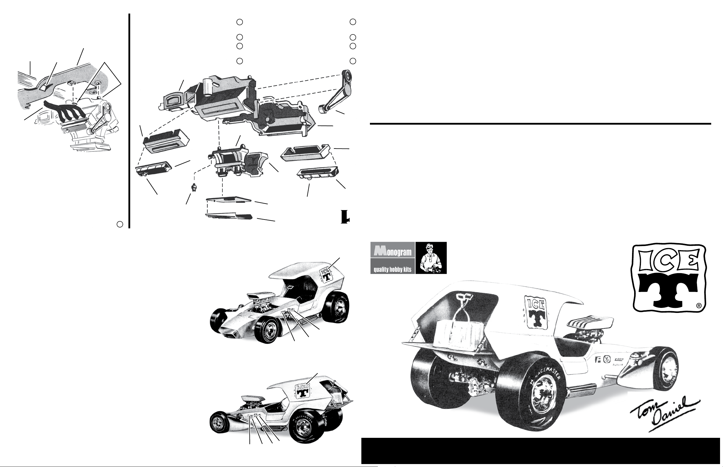
together and attach to top of intake.
8. Cement air scoop halves 11 and 12
front.
7. Attach pulley assembly 10 to engine
6. Cement high riser to top of engine.
rear of high riser.
5. Cement distributor 9 into hole in tab on
1
8H together.
4. Next, cement high riser halves 7H and
as shown.
3. Cement two rocker covers 5H to heads
2. Cement two heads 3 and 4 to engine.
and 2 together
1. Begin by cementing engine halves 1
The car comes complete with melting ice blocks and tongs.
chopped roof, groovy dished hood, and out-of-sight interior.
of competition car. Check out the side exhausts, forward rake,
The body has that low mean look that Tom gives to this kind
quick ller knock-off caps.
scoop. Go juice is carried in two chromed side tanks with
Manifold, giant gas gulpin’ 4 barrel jug, and a slick looking
It’s big thumpin’ V-8 mill is topped by the latest Hi-Rise
like those seen on hot machinery at drag strips everywhere.
This beauty rides on huge real-looking wrinkle slicks, just
creation is stuffed with mouth watering glitter.
latest trend in show/go rod styling, Tom Daniel’s newest
OF A. The Ice “T” comes on like strong. Designed for the
FASTED AND QUICKEST ICE WAGON IN THE U.S.
13
cement it drying.
does not touch the table while the
books so that the bottom of the eingine
openings. Rest the frame between two
pipes should be centered in frame
engine on frame 15. Ends of exhaurst
places indicated on sketch and position
wet on exhaust pipes, add cement to
heads. While cement is still slightly
9. Cement exhaust pipes 13 and 14 to
3
BREATHER CAP
9
PAINTING
Use only PAINT FOR PLASTICS or an ENAMEL for the parts you may wish to paint.
Refer to the box illustrations and the detailed color scheme below.
It is best to paint some of the smaller parts before removing them from the plastic
trees. Use a small pointed brush for the small parts and a 1/4 inch soft brush for larger
areas.
Allow the paint to dry thoroughly before handling the parts. Paint should be scraped
from the areas to be cemented because cement will not adhere to the paint.
GLOSS YELLOW - Body, back pan and scoop.
SEMI GLOSS BLACK - Entire engine assembly including exhaust pipes, entire
frame except bed portion, belts on pulley assembly ve ribs on top of air scoop, ends
of exhaust pipes 25 and 26, surfaces between coil springs on front suspension, entire
front seat and oorboard and inside of air scoop.
LIGHT BROWN (Wood) - Bed portion of frame (this is the portion which carries
the ice).
SILVER - Seven metal strips on bed portion, pulleys and alternator on pulley
assembly and six instruments on front of oorboard.
TRANSPARENT RED - Tail light lenses.
TRANSPARENT BLUE - ICE BLOCKS.
WHITE - Lettering on outside of front and rear tires and narrow stripe on sidewall
of front tire.
®
THE ICE “T”
10
2
7H
check off each step as completed.
4
8. DO NOT RUSH assembly. FOLLOW instructions and
5H
NOT stick to plating.
7. SCRAPE PLATING from plastic parts. Cement WILL
Some parts must be painted before cementing.
3. Read PAINTING INSTRUCTIONS before assembly.
for use. All parts are identified by a number.
2. DO NOT REMOVE parts from trees until ready
8H
Become familiar with your Monogram kit.
STUDY the drawings.
1. READ the instructions.
MODEL BUILDING
EIGHT STEPS TO SUCCESSFUL
11
12
TOWARDS REAR
BREATHER CAP
Too much cement can damage your model.
5H
6. Apply cement with a TOOTHPICK on small areas.
5. CHECK FIT of part before cementing into place.
4. CUT parts from trees, breaking off may damage part.
1
KIT 4266 85426600200
6
3
5
1
DECALS
Use as many decals as you like and locate them to suit your individual taste. The
photos show suggested decal locations. For a neat job, work with one subject at a time
and trim each close to the color outline. Dip in water for a few seconds. When decal
can slide off sheet, slide into position on model and let dry before handling.
5 4
Designed By
6
3
or, please write to: Revell Inc Consumer Service Department, 1850 Howard Street Unit A, Elk Grove Village, Illinois 60007
Be sure to include the plan number (85426600200), part number, description, your return address and phone number.
If you have any questions or comments, call our hotline at: (800) 833-3570
Visit our website: www.revell.com Revell Inc Elk Grove Village, IL. Copyright © 2010. All rights reserved.
Page 2
21H
16H
22H
27H
28
24H
26H
HOLE FOR PIN
ON RADIUS ROD
25H
FRAME
OPENING
RIB FOR
EXHAUST PIPE
19H
SCRAPE PLATING
FROM AXLE AS
SHOWN BY SHADING
17H
20H
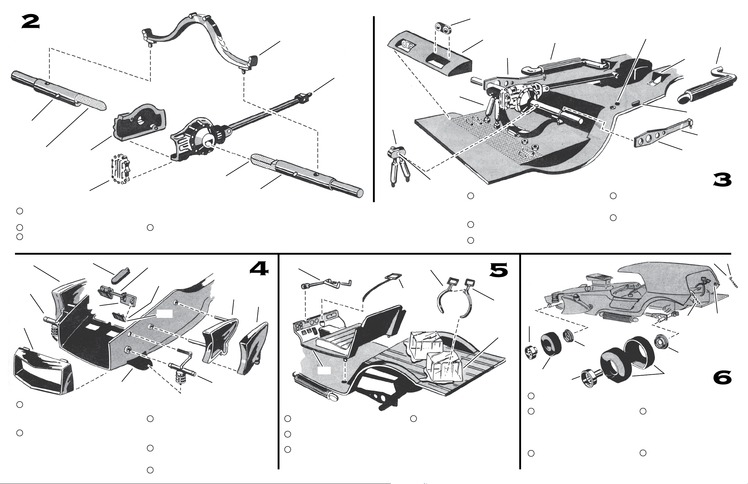
10. Cement quick change halves 16H and 17H
together.
11. Attach cover 20H to quick change halves.
12. Cement axle halves 18H and 19H into “D”
34H
31
35H
33H
30
38H
shaped holes as shown. Make sure holes for
springs in axle face up as shown.
13. Cement spring 21H into holes in axle. While
CENTER ROD
BEVELED
EDGE
29H
SCRAPE PLATING
FROM AXLE AS
SHOWN BY SHADING
cement is slightly wet proceed to next step.
18H
36H
37H
39
22H
CHROME PLATED PART. SCRAPE PLATING
H
WHERE CEMENT MUST GO. CEMENT WILL
NOT STICK TO PLATING.
41H
HOLE FITS
OVER PIN
ON AXLE
42H
14. Now take frame and engine assembly
assembled in Step 1 and turn upside down as
shown. Cement end of driveshaft into engine
and spring between ribs on frame.
15. Cement two shock absorber units 22H to pins
on axle and into holes as shown.
16. Attach two rear radius rods 23H and 24H as
indicated.
43H
45H
ICE
BLOCK
RADIUS ROD
23H
17. Cement pipes 25H and 26H to frame. Front
end of pipe t into frame opening. Rib on frame
ts into notch in exhausts.
18. Next, cement two tailight units 27H ito notches
in back pan 28. Cement back pan to frame in
position as indicated by shaded area. Edge of
back pan rests against the mounts for the shock
absorber units.
PIN
48H
48H
“U” NOTCH FOR
PIN ON CHAIN
SUSPENSION
SUPPORT
19. Cement two headlights 29H against triangular
stops on headlight backs 30. Make certain that
the beveled edge of headlight is in position
shown in sketch before cementing in place.
20. Locate (do not cement) rod on headlight back
between two ribs on body. Now carefully
cement retainer 31 to body. Add cement only
to where retainer touches body. DO NOT
put cement near rod so that headlights will
operate properly. Hold 31 tightly in place
until cement sets.
32H
Do not operate headlights until cement has
dried overnight.
21. Cement two front axles suspensions 32H and
33H to side in body as shown It is best to insert
axle into hole in body, THEN insert small pin
on spring into hold in suspension support.
22. Cement fuel tank halves 34H and 35H together
and cement to body as shown. Repeat for
remaining tank halves 36H and 37H.
23. Next, cement nose piece 38H to front of body.
40
24. Cement steering column 39 into notch in
oorboard 40.
25. Next, cement shift lever 41H into oorboard as
indicated, then cement oorboard to frame.
26. Cement ice tong halves 42H and 43H together.
Pin on one half ts between two pins on other
half. Cement tongs to one ice block.
27. Two ice blocks are now cemented
to the frame as shown. Cement
should be added only to the block
edges not the “puddle” portions.
The arrangement shown may be
changed to suit. It is best to check
for clearance with the body before
cementing into nal position.
44
FRONT
TIRE
28. Cement completed frame assembly and
29. Press inside wheel half 44 into front tire.
30. Fit slick halves together (do not
46H
body together.
Then apply cement to outside wheel
half 45H and press into other side of
tire. Hold wheel halves together until
cement sets. Cement wheels to front
axle.
cement) lining up the “at” wrinkled
portion. One slick half has a rib around
47
SLICK
the inside which ts into the groove
around the inside of the other half.
31. Fit the outside rear wheels 46H into
the assembled slicks and cement
the wheels to the inner wheel
halves 47. Now cement wheel to
rear axle. Flat portion of slick lies
at on table.
32. Complete your model by cementing
two tailgate chains 48H in place as
indicated.
 Loading...