

REVELL Buzz Aldrin NASA Apollo Spacecraft User Manual [en, fr, nl, it, gr, da, no, fi, sv, es, pt, de, en, hr, et, fi, hu, lv, lt, nl, pl, ro, ru, sr, sk, sl, cs, tr, gr, bg, uk, ch, he, ar, ja, ch, ch, ko, hi, id, kk, ms, fa, pt, es, th, vi, sq, mk]
Page 1
KIT 5086 85508600200
The historic Apollo Spacecraft that transported Astro-
nauts to the moon for the first time consisted of two main
parts, the Command Module and the Service Module.
The Command Module contained the living quarters for
the three men, as well as extensive electronics, communications and guidance systems. It was supplied with
oxygen and electric power from the Service Module,
which also contained the main propulsion engine for attaining luner orbit and for firing into the return trip. After
completing the entire mission to and around the moon
and back toward earth together, the two modules separated just minutes before entering the atmosphere leaving only the Command Module to return to earth. The
bright gold color on this model simulates the gold foil
protective heat covering of the actual Command Module.
Interior details abound, such as figures of the three
Apollo astronauts, instrument and control panels with
authentic panel waterslide decals, structural members, parachutes, antenna, oxygen and hydrogen
tanks, and fuel cells may be viewed through transparent side sections. The model is 12 3/4" long and
stands 8 5/8" tall on it's own display base. Engine nozzle extension and high-gain antenna are removeable.
APOLLO SPACECRAFT
* REPEAT SEVERAL TIMES
* A REPETER PLUSIEURS FOIS
READ THIS BEFORE YOU BEGIN LIRE CE QUI SUIT AVANT DE COMMENCER
* Study the assembly drawings.
* Each plastic part is identified by a number.
* In the assembly drawings, some parts will be
marked by a star (★) to indicate chrome
plated plastic.
* For better paint and decal adhesion, wash
the plastic parts in a mild detergent solution.
Rinse and let air dry.
* Check the fit of each piece before
cementing in place.
* Use only cement for polystyrene plastic.
* Scrape plating and paint from areas
to be cemented.
* Allow paint to dry thoroughly before
handling parts.
* Any unused parts may be discarded.
DECAL APPLICATION INSTRUCTIONS
1. Cut desired decal from sheet.
2. Dip decal in water for a few seconds.
3. Place wet decal on paper towel.
4. Wait until decal is movable on paper backing.
5. Place decal in position on model, face up and
slide backing away.
6. Press out air bubbles with a soft damp cloth.
7. Milkiness that may appear is for better decal
adhesion and will dry clear. Wipe away any
excess adhesive.
8. Do not touch decal until fully dry.
9. Allow the decals 48 hours to dry before
applying clear coat.
NOTE: Decals are compatible with
setting solutions or solvents.
* OPTIONAL PARTS
* PIECES EN OPTION
* DECAL
* DECAL COMANIE
* Etudier les schémas de montage.
* Chaque pièce en plastique est identifiée par un numéro.
* Sur les schémas de montage, certaines pièces sont
marquées d'une étoile (★) pour indiquer qu'elles sont en
plastique chromé.
* Pour une meilleure prise de la peinture et des autocollants,
laver les pièces en plastique avec une solution détergente
peu concentrée. Les rincer et les laisser sécher à l'air.
* Vérifier que chaque pièce s'ajuste bien avant
de la coller en place.
* N'utiliser que de la colle pour polystyrène.
* Gratter les parties à coller pour enlever le chrome et la peinture.
* Laisser la peinture bien sécher avant de manipuler les pièces.
* Toute pièce inutilisée peut être jetée.
DIRECTIVES D'APPLICATION DES AUTOCOLLANTS
1. Découper l'autocollant désiré de la feuille.
2. Tremper l'autocollant dans de l'eau pendant quelques secondes.
3. Placer l'autocollant mouillé sur une serviette en papier.
4. Attendez que l'autocollant puisse être déplacé sur son support
en papier.
5. Mettre l'autocollant en position sur le modèle face sur
le dessus et faire glisser le support pour l'enlever.
6. Appuyer avec un chiffon doux humide pour éliminer les bulles d'air.
7. La substance laiteuse qui peut apparaître est destinée à
améliorer l'adhésion de l'autocollant et devient incolore au
séchage. Essuyer pour enlever tout excédent d'adhésif.
8. Ne pas toucher l'autocollant tant qu'il n'est pas bien sec.
9. Laisser l'autocollant sécher pendant 48 heures avant
d'appliquer une couche transparente.
REMARQUE: Les autocollants sont compatibles avec
* ALTERNATIVE ASSEMBLY
* ENSEMBLAGE ALTERNATIVE
les solutions de fixage ou les solvants.
* CEMENT TOGETHER
* A COLLER
* REMOVE AND THROW AWAY
* A RETIRER ET JETER
* DO NOT CEMENT
* NE PAS COLLER
This optional paint guide is provided if
you choose to detail paint your model.
Ce guide de peinture vous sera fourni si vous choisissez
de peindre votre modèle en détail.
Gloss Black
Matte Black
Light Blue
Dark Blue
Light Gray
Dark Gray
Light Brown
Tan
White
Silver
Gold
Yellow
Interior Green
Noir lustre
Noir mat
bleu clair
Bleu fonce
Gris clair
Gris fonce
Marron clair
Brun clair
blanc
Argent
Dore
Jaune
Interior vert
(Zinc Chromate)
Maroon
Gloss Red
Marron
Rouge brillant
If you have any questions or comments, call our hotline at: (800) 833-3570
or, please write to:
Revell Inc Consumer Service Department, 1850 Howard Street Unit A, Elk Grove Village, Illinois 60007
Be sure to include the plan number (85508600200), part number, description, your return address and phone number.
Visit our website: www.revell.com
Revell Inc Elk Grove Village, IL. Copyright © 2009. All rights reserved.
Page 2
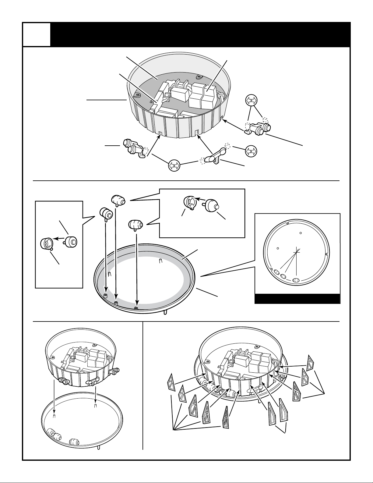
1
FLOOR / HEATSHIELD ASSEMBLY
INTERIOR GREEEN
(ZINC CHROMATE)
REACTION CONTROL
6
HELIUM TANK
HALF
2
FLOOR
4
ENGINE
sILVER
LIGHT BROWN
LIGHT GRAY
9
OXIDIZER TANK
HALF
LIGHT GRAY
8
OXIDIZER TANK
HALF
REACTION CONTROL
REACTION CONTROL
5
ENGINE
sILVER
4
ENGINE
sILVER
7
HELIUM TANK
HALF
INTERIOR GREEEN
(ZINC CHROMATE)
1
HEAT SHIELD
TOP VIEW
3
SUPPORT
FRAMES
Kit 5086 - Page 2
3
SUPPORT
FRAMES
49
SUPPORT
FRAMES
Page 3
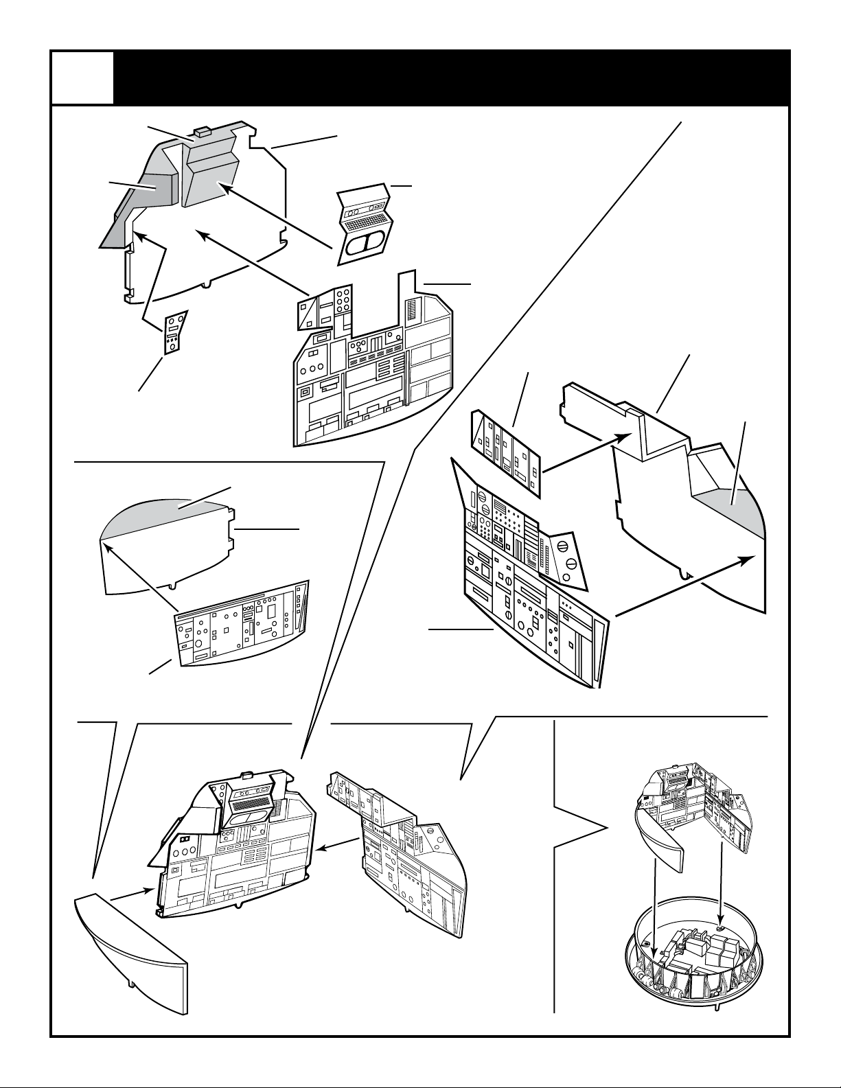
2
WALL ASSEMBLY
INTERIOR GREEEN
(ZINC CHROMATE)
MATTE
BLACK
M
INTERIOR GREEEN
(ZINC CHROMATE)
12
WALL
L
J
11
WALL
K
INTERIOR GREEEN
(ZINC CHROMATE)
10
WALL
F
G
Kit 5086 - Page 3
Page 4
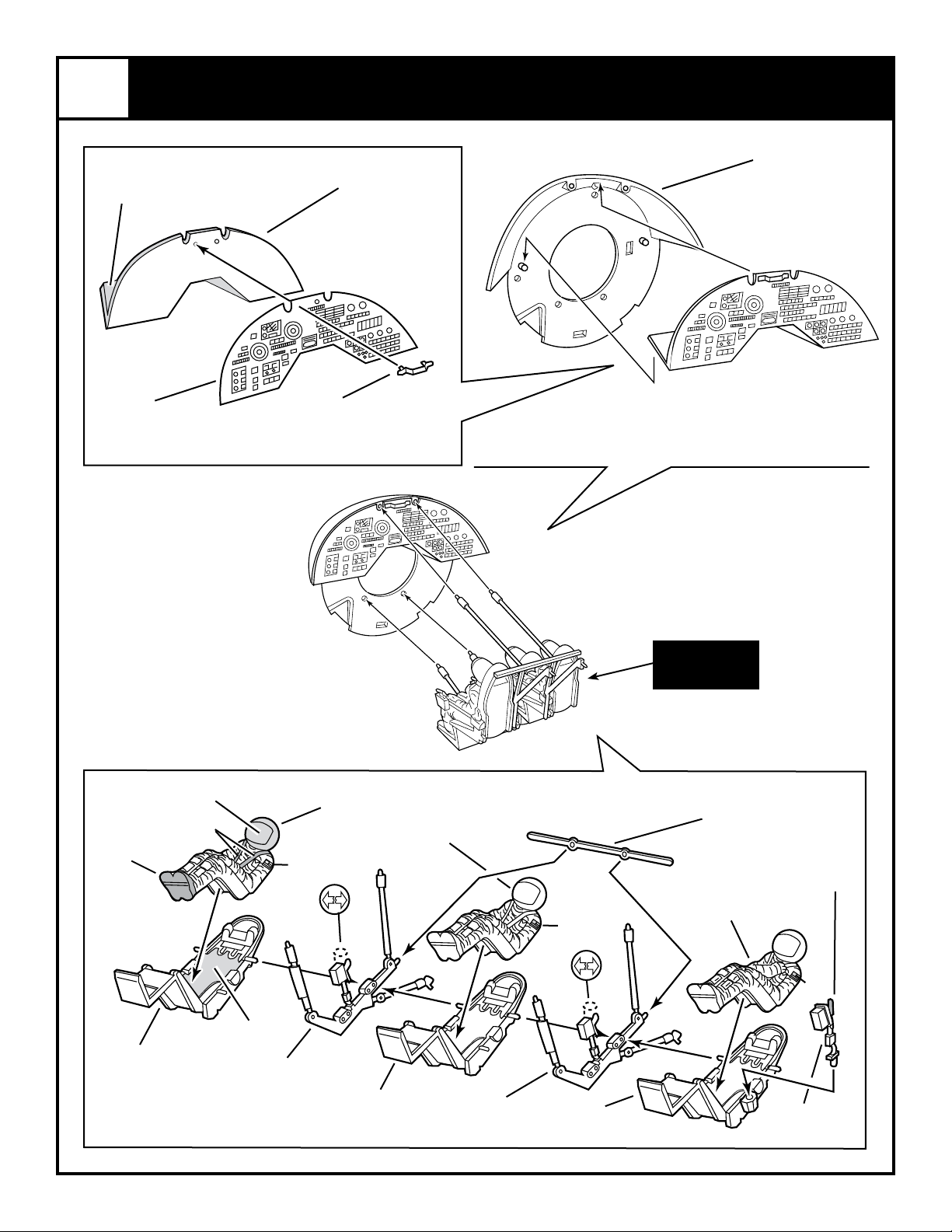
3
iNTeriOr GreeeN
(ZiNC CHrOMATe)
COMMAND MODULE / ASTRONAUT ASSEMBLY
23
22
INSTRUMENT
PANEL
COMMAND
MODULE
(CM) TOP
iNTeriOr GreeeN
(ZiNC CHrOMATe)
dArk GrAy
I
dArk GrAy
liGHT blue
80
HAND BAR
silver
19
ASTRONAUT
red
20
ASTRONAUT
red
COUCH
ASSEMBLY
CROSSPIECE
dArk GrAy
21
ASTRONAUT
18
MATTe blACk
13
COUCH
dArk GrAy
Kit 5086 - Page 4
TAN
16
COUCH SUPPORT
dArk GrAy
14
COUCH
dArk GrAy
16
COUCH SUPPORT
dArk GrAy
15
COUCH
dArk GrAy
red
17
CONTROL
Page 5

3
COMMAND MODULE ASSEMBLY CONTIN
gloss black
gloss red
tan
LANDING SUBSYSTEM
silver
UED
24
4
33
PROBE
TOP
5
WINDOW
25
silver
COMMAND MODULE
(CM) BODY
32
PROBE
SUPPORT
31
PROBE
SUPPORT
PROBE ASSEMBLY
gloss red
30
PROBE
SUPPORT
28
PROBE
SUPPORT
PROBE
SUPPORT
27
PROBE BODY
DOCKING RING
29
COMMAND MODULE BODY ASSEMBLY
34
clear
35
WINDOW
clear
36
(CM) SECTION
clear
26
gloss
black
COMMAND MODULE
26
(CM) BODY
gold
39
DUMP NOZZLES
Kit 5086 - Page 5
Page 6

5
COMMAND MODULE ASSEMBLY
37
E.v.A. HANDLES
CONTINUED
6
A
37
E.v.A. HANDLES
38
HANDLES
SERVICE MODULE TANKS ASSEMBLY
40
FUEL CELL
TOpS
light gray
B
gold
43
OXYGEN TANK
TOp
C
gold
45
HYDROGEN
TANK TOp
light gray
Kit 5086 - page 6
FUEL CELL
FUEL CELLS
41
SHELF
42
OXYGEN TANK
BOTTOmS
gold
gold
44
HYDROGEN
TANK BOTTOm
OXYGEN TANKHYDROGEN TANK
Page 7

7
SERVICE MODULE ASSEMBLY
SERVICE MODULE (SM)
55
BODY HALF
white
white
dark blue
dark blue
dark blue
white
dark blue
A
B
dark blue
C
54
COMPARTMENT
WALL
silver
light
gray
50
FUEL OXIDIZER
TANK HALF
light gray
iNteriOr greeeN
(ZiNC ChrOMate)
52
HELIUM TANK
HALF
iNteriOr greeeN
(ZiNC ChrOMate)
53
HELIUM TANK
HALF
iNteriOr greeeN
(ZiNC ChrOMate)
iNteriOr greeeN
(ZiNC ChrOMate)
51
FUEL OXIDIZER
TANK HALF
light gray
Kit 5086 - Page 7
Page 8

7
SERVICE MODULE ASSEMBLY CONTINUED
white
white
white
white
57
(SM) BODY
HALF
46
FUEL SUMP
TANK HALF
maroon
silver
48
FUEL TANK
BRACKET
silver
47
FUEL SUMP
TANK HALF
maroon
white
Kit 5086 - Page 8
56
(SM) SECTION
clear
Page 9

8
63
CAP
SERVICE MODULE BOTTOM ASSEMBLY
58
PIVOT
62
(SM) BOTTOM
60
COLLOR
gloss
yellow
59
PIVOT
gloss
black
61
NOZZLE
SUPPORT
gloss
black
gloss red
NOZZLE EXTENSION
65
(SM) TOP
64
silver
dark blue
71
E.V.A. LIGHT
silver
gloss
yellow
75
V.H.F. ANTENNA
76
UMBILICAL
BOOM
77
CAP
silver
75
V.H.F. ANTENNA
Kit 5086 - Page 9
Page 10

9
ANTENNA ASSEMBLY
FEED HORNS
gloss black
66
REFLECTOR
68
ANTENNA SUPPORT
67
silver
69
WIDE BEAM
HORN
white
68
FEED HORN
gloss black
66
REFLECTOR
70
RETAINER
10
REACTION CONTROL
ENGINE
flat black
REACTION CONTROL
74
white
74
ENGINE
white
CONTROL ENGINE ASSEMBLY
72
CONTROL ENGINE
HOUSING TOP
white
73
CONTROL ENGINE
HOUSING BOTTOM
white
REACTION CONTROL
REACTION CONTROL
74
ENGINE
white
flat black
74
ENGINE
white
Kit 5086 - Page 10
Page 11

11
FINAL ASSEMBLY
light gray
OPEN
CLOSE
79
BASE HALF
78
BASE HALF
H
Kit 5086 - Page 11
Page 12

12
decal placement
B
A
E
SILVER
C
E
E
MATTE BLACK
C
CC
C
D
C
D
C
C
Kit 5086 - Page 12
A
E
B
 Loading...