

Page 1

Ultima V oice Loudspeaker
Page 2

TABLE OF CONTENTS
INTRODUCTION...............................................3
ABOUT THE MANUAL AND WARRANTY.................................3
DESCRIPTION .................................................4
MIDRANGE .......................................................................4
WOOFERS ........................................................................4
TWEETERS........................................................................5
CROSSOVER NETWORK .....................................................5
CABINET...........................................................................5
PLACEMENT ...................................................6
SPEAKER CONNECTIONS .................................8
SINGLE-WIRED SYSTEM CONNECTIONS ..............................8
BI-WIRED SYSTEM CONNECTIONS ......................................9
BI-AMPLIFIED SYSTEM CONNECTIONS...............................10
SYSTEM OPTIMIZATION..................................12
CABINET CARE..............................................13
SPEAKERS AND POWER ................................13
PANEL REPLACEMENT...................................14
SPECIFICATIONS............................................16
SERVICE INFORMATION..................................18
VOICE Speaker
Owner’s Manual
2
Page 3

Figure 1. The VOICE
center-channel speaker.
INTRODUCTION
With its striking and sophisticated appearance, the Revel Ultima
VOICE center-channel speaker hints at its advanced design from the
first glance. The simple, clean lines characterize an exceptional sound
reproduction system defined by custom-designed drivers, individually optimized crossover network, and a highly-functional enclosure.
We created the VOICE speaker to achieve superior performance in
the widest possible range of multi-channel environments. Physically
small enough to be used in modest rooms, it is dynamic enough to
be used in very large rooms. It is equally at home in discriminating
multi-channel audiophile systems or home theater systems.
Moreover, we’ve taken the care to make it as adaptable as possible to
a variety of system placements and the acoustical interactions typically found in multi-channel systems.
ABOUT THE MANUAL AND WARRANTY
To begin enjoying your VOICE speaker, first read and then perform
the instructions in this owner’s manual. Maximum performance is
dependent on following all instructions described here, as well as
those found in the owner’s manuals of associated components in
your audio system. Save these instructions for future reference.
The Revel Ultima VOICE center-channel speaker is covered by a
limited 5-year warranty, so save the bill of sale to protect your purchase and aid in any service-related questions.
VOICE Speaker
Owner’s Manual
3
,,,,,,,,,,,,,,,,,,,,
,,,,,,,,,,,,,,,,,,
,,,,,,,,,,,,,,,,
,,,,,,,,,,,,,,
,,,,,,,,,,,,
,,,,,,,,,,
,,,,,,,,
,,,,,,
,,,,
,,
Page 4
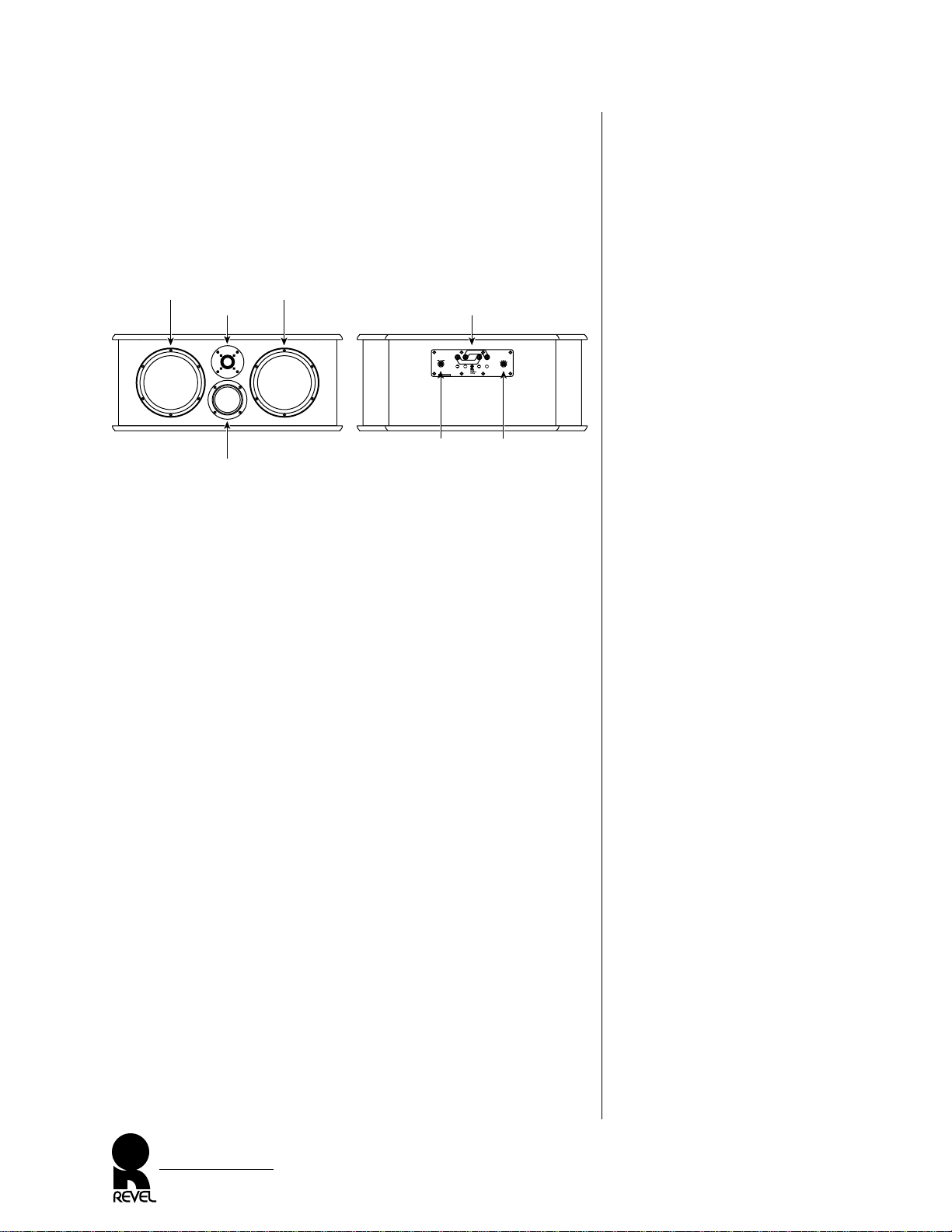
Figure 2. The VOICE transducer
and connection locations.
DESCRIPTION
The Ultima VOICE center-channel speaker uses two 8-inch mica
and carbon-filled copolymer woofers to reproduce the lower
octaves. A 4-inch titanium transducer reproduces the very important midrange frequencies. A 1-inch textile-dome tweeter reproduces higher frequencies.
Combined with an individually-optimized crossover network, this
transducer arrangement provides a uniform “listening window” or
area in which the sound varies little. Also, the large woofer size is
used to reproduce center channel information and all its dynamics
without compression.
MIDRANGE
To ensure accurate detail, each VOICE speaker has a 4-inch
midrange that is unique in the following ways:
• The midrange’s radiating surface is made of titanium for true
pistonic behavior throughout its operating range.
• The midrange’s motor system utilizes neodymium magnets with a
stray-flux containment system for shielding near video monitors.
• The cast magnesium frame provides optimum voice coil cooling
and minimum reflections, while offering excellent rigidity.
WOOFERS
To ensure uncompressed dynamic range, each VOICE speaker uses
a pair of 8-inch woofers that are unique in the following ways:
• The woofer’s radiating surface is made of an injection-molded
polymer material with incredible stiffness and internal damping.
• Optimized magnetic circuits to minimize harmonic distortion.
VOICE Speaker
Owner’s Manual
4
Install straps for
single-wired operation
Note:
Remove straps
for bi-wired
or bi-amplified
operation
Install straps for
single-wired operation
Low Frequency Input High Frequency Input
High Frequency
Level (dB)
0
+.5
-.5
+1
-1
Placement
Compensation
(See Owner's Manual)
Serial Number
Revel Corporation
Chatsworth, California
Made in U.S.A.
On Top Of
Monitor
Flush
Mounted
Stand
Mounted
VOICE Front VOICE Rear
Woofer
Tweeter
Midrange
Woofer
High-Frequency
Level Control
Placement
Compensation
Control
Connectors (with
shorting straps)
Page 5

• Oversized 2-inch diameter voice coil with flat aluminum wire
offer higher power handling than average-sized coils for greater
accuracy at high volume levels and during extended crescendos.
TWEETERS
Each VOICE speaker also contains a high-performance tweeter
with the following features:
• Optimized tweeter-dome profiles for maximum dispersion,
while eliminating coloration caused by “break-up modes.”
• Linear reproduction with very-low harmonic distortion even at
high output levels for uncompressed sound purity.
• The tweeter utilizes a large voice-coil with an oversized surround
roll. This provides the higher power handling and longer excursion
capability required to reproduce greater uncompressed dynamics.
CROSSOVER NETWORK
Built into each VOICE speaker is an individually-optimized
crossover network with the following features:
• A 3-way, 24 dB per octave crossover at 300 Hz and 2.2 kHz
shapes the on- and off-axis response of each driver and the complete system.
• Hand-wired filter networks with air-core inductors and film
capacitors are calibrated to match each Ultima VOICE speaker
to the reference standard.
• Provision for bi-amplified and bi-wired applications via removable external shorting straps on the gold-plated binding posts.
• External level controls for the tweeter via calibrated switched
precision resistors, thus maintaining identical response from
both speakers for ideal imaging.
• External LF tilt control for speaker placement optimization.
CABINET
The cabinet offers groundbreaking appearance and aids in overall
system performance. The inner enclosure is designed as an acoustically-inert platform for sound-wave generation. Integral top and
bottom panels provide a custom look via available finishes (see
Panel Replacement on page 14) and are internally damped by sandwiched viscoelastic energy-absorbing layers to reduce any sound
transmission effects.
VOICE Speaker
Owner’s Manual
5
Page 6

Figure 3. VOICE center-channel
speaker mounted on its (optional) pedestal below a front projection video system.
PLACEMENT
Sound quality is heavily dependent on the accuracy of all your
speakers, their placement in the listening room, and the acoustics
of the room itself. Since the VOICE center-channel speaker is
extremely accurate, experiment with the following speaker systems
and placements (Figures 3 through 5) to enhance performance.
NOTE: The VOICE center-channel speaker includes a user-adjustable
placement compensation circuit that tailors the response for a desired
application (e.g., stand mounting, flush mounting, or on top of monitor). See “System Optimization” on page 12 for detailed use on the
PLACEMENT COMPENSATION control.
VOICE Speaker
Owner’s Manual
6
left
right
VOICE
center
Placement Compensation
set to STAND MOUNTED
(see page 12)
VOICE Pedestal
(optional)
Front Projection
Screen
Page 7

Figure 4. VOICE center-channel
speaker mounted on top of rear
projection monitor.
Figure 5. VOICE center-channel
speaker flush-mounted in large
wall unit.
VOICE Speaker
Owner’s Manual
7
left
VOICE
center
right
Rear Projection
Monitor
Placement Compensation set to
TOP OF MONITOR (see page 12)
left
VOICE
center
right
Rear Projection
Monitor
Wall Unit
Placement Compensation set to
FLUSH MOUNTED (see page 12)
Page 8
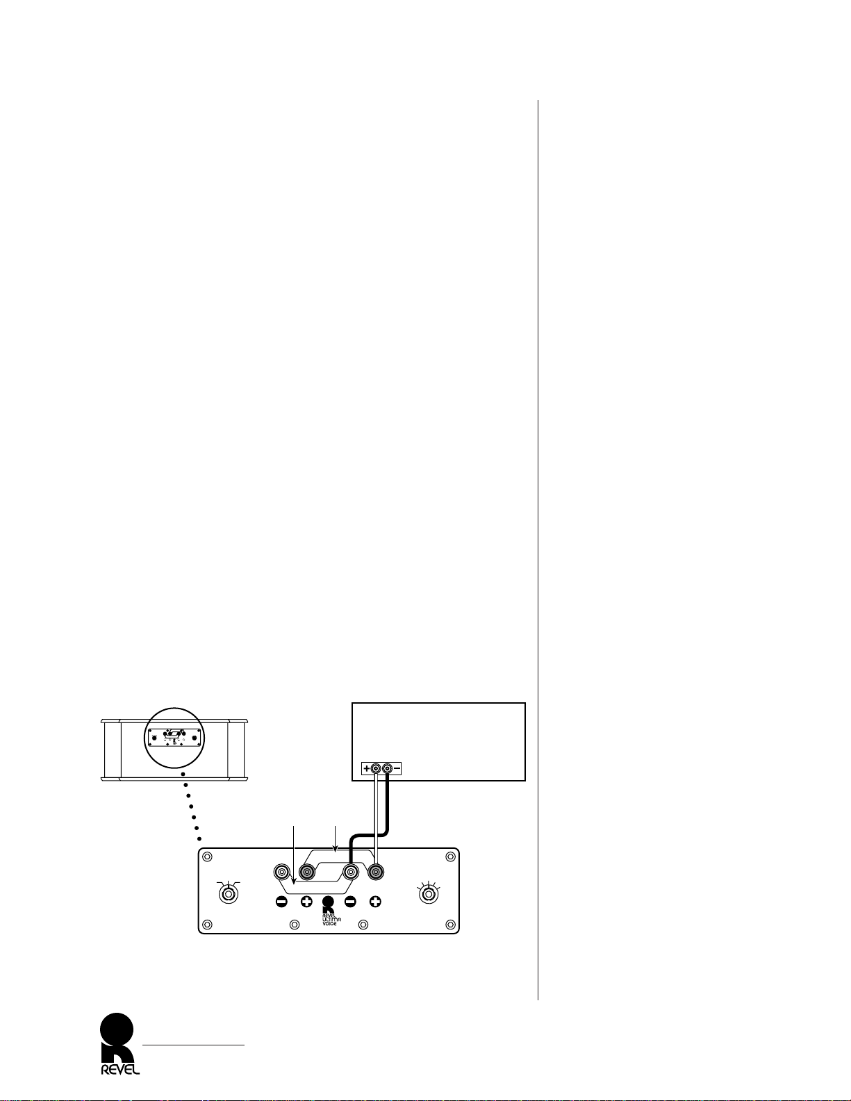
Figure 6. How to connect the
VOICE center-channel speaker
in a single-wired system, the most
common type of installation.
SPEAKER CONNECTIONS
The VOICE center-channel speaker can be connected to your audio
system in three different ways: single-wired, bi-wired or bi-amplified.
Please read the following three sections before proceeding with the
actual connections. Also, be sure to observe the following points:
• Use high-quality speaker cable (maximum total loop resistance
of 0.1 ohms per channel) with high-quality connectors between
the speaker and your audio system. Consult your Revel dealer as
to specific recommendations for your application.
• Turn off all audio system power before making any connections.
• Read the owner’s manuals that were included with your audio
components to confirm their connection procedures.
• Verify correct polarities (i.e., + to + and - to -) when making
connections. Failure to do so will cause poor imaging and
diminished bass response.
• For bi-wired or bi-amplified applications, remove the shorting
straps on the rear of the VOICE speaker (refer to Figures 7, 8,
and 9 on the next three pages).
SINGLE-WIRED SYSTEM CONNECTIONS
For most applications, simply leave the shorting straps in place and
connect the + and − from a single amplifier channel to the HIGH
FREQUENCY INPUT terminals on the rear of the speaker, as
shown in Figure 6.
VOICE Speaker
Owner’s Manual
8
VOICE Rear
Install straps for
single-wired operation
Note:
Remove straps
for bi-wired
or bi-amplified
operation
Install straps for
single-wired operation
Low Frequency Input High Frequency Input
High Frequency
Level (dB)
0
+.5
-.5
+1
-1
Placement
Compensation
(See Owner's Manual)
Serial Number
Revel Corporation
Chatsworth, California
Made in U.S.A.
On Top Of
Monitor
Flush
Mounted
Stand
Mounted
Amplifier
(rear)
(one channel shown)
white red
Connector Panel
Shorting Straps
(leave in place)
Install straps for
single-wired operation
Install straps for
single-wired operation
Low Frequency Input High Frequency Input
High Frequency
Level (dB)
0
+.5
-.5
+1
-1
Placement
Compensation
(See Owner's Manual)
Serial Number
xxxx
On Top Of
Monitor
Flush
Mounted
Stand
Mounted
Page 9

Figure 7. How to connect
the VOICE center-channel
speaker in a bi-wired system.
BI-WIRED SYSTEM CONNECTIONS
A bi-wired system involves two pairs of speaker wires connected to a
single amplifier channel. On the rear of the VOICE speaker, remove
the shorting straps and connect the + and − of one pair of wires to
the HIGH FREQUENCY INPUT terminals and the + and − of
the other pair of wires to the LOW FREQUENCY INPUT terminals, as shown in Figure 7. Check with your Revel dealer for recommendations and possible benefits for your application.
VOICE Speaker
Owner’s Manual
9
VOICE Rear
Install straps for
single-wired operation
Note:
Remove straps
for bi-wired
or bi-amplified
operation
Install straps for
single-wired operation
Low Frequency Input High Frequency Input
High Frequency
Level (dB)
0
+.5
-.5
+1
-1
Placement
Compensation
(See Owner's Manual)
Serial Number
Revel Corporation
Chatsworth, California
Made in U.S.A.
On Top Of
Monitor
Flush
Mounted
Stand
Mounted
Amplifier
(rear)
(one channel shown)
white red
Connector Panel
Shorting Straps
Removed
Low Frequency Input High Frequency Input
High Frequency
Level (dB)
0
+.5
-.5
+1
-1
On Top Of
Monitor
Flush
Mounted
Stand
Mounted
Placement
Compensation
(See Owner's Manual)
Serial Number
xxxx
Page 10

Figure 8. How to connect the
VOICE speaker in a vertical
bi-amplified system.
SPEAKER CONNECTIONS
(CONTINUED)
BI-AMPLIFIED SYSTEM CONNECTIONS
You can connect the VOICE speaker in either a vertical or horizontal bi-amplified system without requiring an additional electronic crossover.
VERTICAL BI-AMPLIFIED SYSTEM
Using two identical amplifier channels, remove the shorting straps
from the rear panel; then connect the VOICE speaker, as shown in
Figure 8.
CAUTION: Failure to remove the shorting straps when biamplifying may damage some amplifiers.
NOTE: When using two dissimilar amplifiers, connect the VOICE
speaker in a horizontal bi-amplified system (see the next section).
VOICE Speaker
Owner’s Manual
10
VOICE Rear
Install straps for
single-wired operation
Note:
Remove straps
for bi-wired
or bi-amplified
operation
Install straps for
single-wired operation
Low Frequency Input High Frequency Input
High Frequency
Level (dB)
0
+.5
-.5
+1
-1
Placement
Compensation
(See Owner's Manual)
Serial Number
Revel Corporation
Chatsworth, California
Made in U.S.A.
On Top Of
Monitor
Flush
Mounted
Stand
Mounted
Amplifier
(rear)
Ch. 1 Ch. 2
(“Y” Adaptor)
INPUT INPUT
Multi-Channel Controller
(rear)
CENTER OUTPUT
white red
Connector Panel
Shorting
Straps
Removed
Low Frequency Input High Frequency Input
High Frequency
Level (dB)
0
+.5
-.5
+1
-1
On Top Of
Monitor
Flush
Mounted
Stand
Mounted
Placement
Compensation
(See Owner's Manual)
Serial Number
xxxx
Page 11

Figure 9. How to connect the
VOICE speaker in a horizontal
bi-amplified system.
HORIZONTAL BI-AMPLIFIED SYSTEM
Using two amplifier channels, remove the shorting straps from the
rear panel; then connect the VOICE speaker, as shown in Figure 9.
CAUTION: Failure to remove the shorting straps when biamplifying may damage some amplifiers.
NOTE: If the “gain factor” of the two amplifier channels is not identical, a means of adjusting the output level of at least one of the channels
is required. Consult your Revel dealer for specific recommendations.
VOICE Speaker
Owner’s Manual
11
VOICE Rear
Install straps for
single-wired operation
Note:
Remove straps
for bi-wired
or bi-amplified
operation
Install straps for
single-wired operation
Low Frequency Input High Frequency Input
High Frequency
Level (dB)
0
+.5
-.5
+1
-1
Placement
Compensation
(See Owner's Manual)
Serial Number
Revel Corporation
Chatsworth, California
Made in U.S.A.
On Top Of
Monitor
Flush
Mounted
Stand
Mounted
(one channel shown –
use for high frequencies)
(one channel shown –
use for low frequencies)
Amplifier
(rear)
INPUT
Amplifier
(rear)
INPUT
(“Y” Adaptor)
Multi-Channel Controller
(rear)
CENTER OUTPUT
white red
Connector Panel
Shorting
Straps
Removed
Low Frequency Input High Frequency Input
High Frequency
Level (dB)
0
+.5
-.5
+1
-1
On Top Of
Monitor
Flush
Mounted
Stand
Mounted
Placement
Compensation
(See Owner's Manual)
Serial Number
xxxx
Page 12

Figure 10. The VOICE level
and placement control locations
and initial settings.
SYSTEM OPTIMIZATION
1. After connecting the VOICE speaker, initially set the HIGH
FREQUENCY LEVEL control on the rear panel to the “0”
position (see Figure 10).
2. Intially set the PLACEMENT COMPENSATION control (see
Figure 10) to match the application as follows:
• Use the Flush Mounted setting when the VOICE is flush-
mounted in a wall or custom-built “media wall”, or is placed
on a bookshelf.
• Use the Top of Monitor setting when the VOICE is placed
on top of a rear projection monitor.
• Use the Stand Mounted setting when the VOICE is placed
on its (optional) VOICE Pedestal.
3. Turn on the system power and play a variety of material. Slowly
increase the volume to a comfortable level and listen from your
main listening position. Be sure to set your multi-channel controller to a mode that utilizes the center channel. If the VOICE
is used in a home theater system, listen to well-recorded dialog
from more than one film, as the sound quality can vary greatly.
VOICE Speaker
Owner’s Manual
12
VOICE Rear
Install straps for
single-wired operation
Note:
Remove straps
for bi-wired
or bi-amplified
operation
Install straps for
single-wired operation
Low Frequency Input High Frequency Input
High Frequency
Level (dB)
0
+.5
-.5
+1
-1
Placement
Compensation
(See Owner's Manual)
Serial Number
Revel Corporation
Chatsworth, California
Made in U.S.A.
On Top Of
Monitor
Flush
Mounted
Stand
Mounted
Connector Panel
Install straps for
single-wired operation
Note:
Remove straps
for bi-wired
or bi-amplified
operation
Install straps for
single-wired operation
Low Frequency Input High Frequency Input
High Frequency
Level (dB)
0
+.5
-.5
+1
-1
On Top Of
Monitor
Flush
Mounted
Stand
Mounted
Set High-Frequency
Level Control To “0”
Set Placement Compensation Control
To Match VOICE Placement
Bass
Increases
Page 13

4. If desired, experiment with placement (see page 6) and try other
PLACMENT COMPENSATION control settings to achieve
the best overall tonal balance, image specificity, and spaciousness. There is no right or wrong placement or setting – only
what sounds best.
NOTE: Rotating the PLACEMENT COMPENSATION control
to the right increases low-frequency output (see Figure 10).
5. You may also wish to further adjust the tweeter’s HIGH FREQUENCY LEVEL control (see Figure 10) to achieve the most
natural sound in your room. Varying the control will change
the high frequency balance and timbre.
CABINET CARE
Each VOICE speaker cabinet has a paint finish and does not
require any routine maintenance. Use a soft cloth, dampened with
water only, to remove any fingerprints or to wipe off dust. Clean
the grille by gentle vacuuming.
For wood (top and bottom) panels, occasionally use a household
furniture polish to maintain the beauty of the hardwood veneers.
For aluminum panels, use a soft cloth, dampened with soapy water
only and wipe in the grain’s direction.
SPEAKERS AND POWER
A VOICE speaker uses high-order crossovers with steep cut-offs to
eliminate damage caused by “out of band” frequencies. Using this
approach, in combination with carefully selected components and
transducers, gives us confidence that a VOICE speaker will not
fail, even under extreme conditions. However, there is a limit to
how loud any speaker can play continuously. A good rule of
thumb is to avoid playing the system at volume levels beyond
where the sound is “clear.” If the sound becomes distorted or
strained, reduce the volume level immediately to avoid damage.
If you are unsure of the suitability of current or planned amplifier
components, please ask your Revel dealer to review them before
connecting your Ultima VOICE center-channel speaker.
VOICE Speaker
Owner’s Manual
13
Page 14
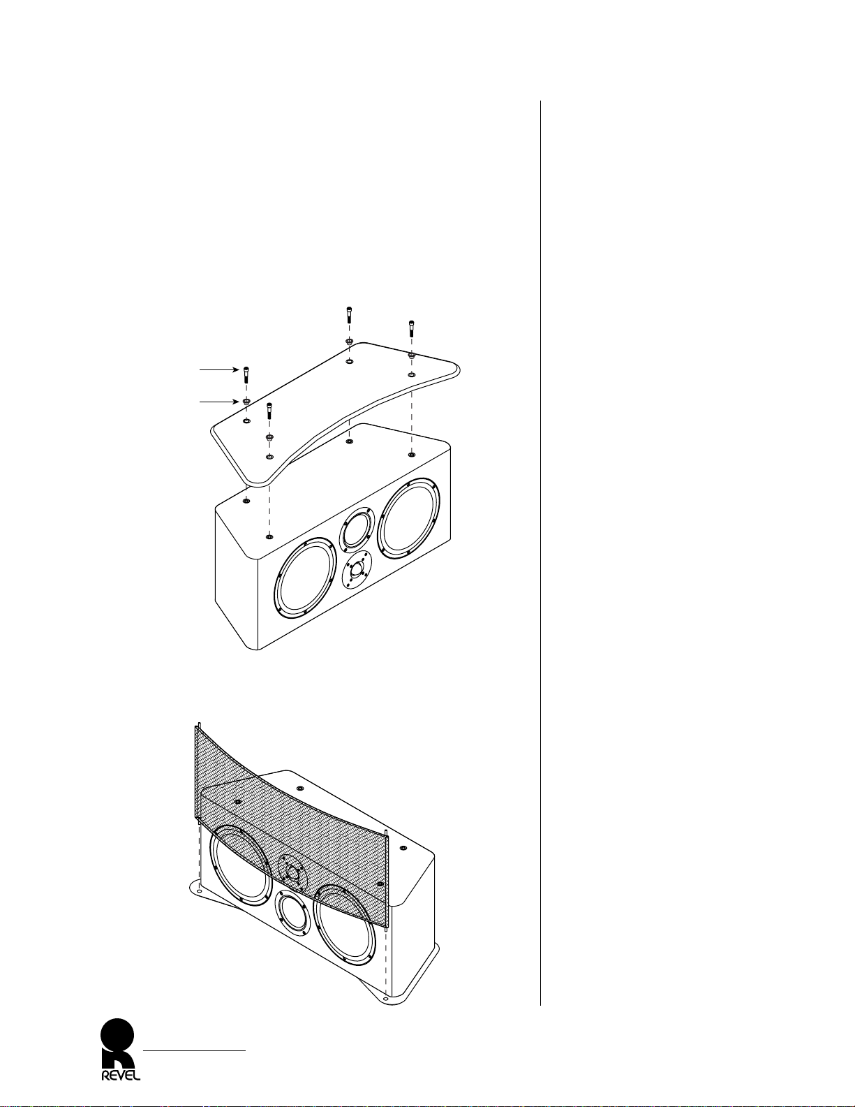
Figure 11. Installing a new
VOICE panel.
Figure 12. Installing the VOICE
speaker grille.
PANEL REPLACEMENT
Although your new VOICE speaker is preassembled at the factory,
you can replace existing panels with new ones as follows:
1. Place the speaker on a soft surface. Use the enclosed hex wrench
to untighten panel bolts. Remove each panel and grille.
2. Install a new panel (see Figure 11). Start all four bolts (with
trim rings) by hand and tighten them with the hex wrench. Be
careful not to overtighten.
3. Turn the speaker over, as shown in Figure 12. Install the speaker
grille. Insert the grille tips into panel cups.
VOICE Speaker
Owner’s Manual
14
Bolt
Trim
Ring
,,,,,,,,,,,,,,,,,,,,
,,,,,,,,,,,,,,,,,,
,,,,,,,,,,,,,,,,
,,,,,,,,,,,,,,
,,,,,,,,,,,,
,,,,,,,,,,
,,,,,,,,
,,,,,,
,,,,
,,
Page 15
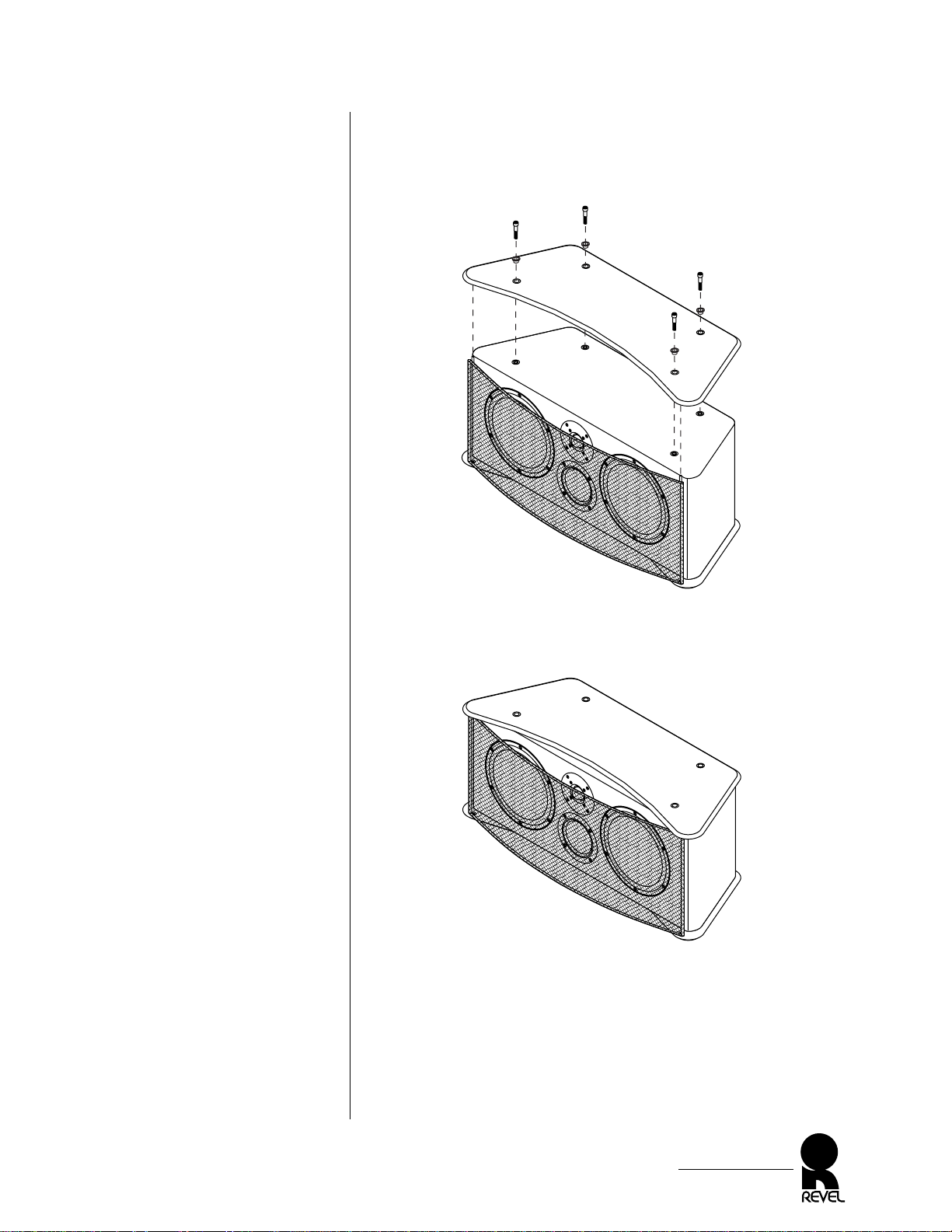
Figure 13. Installing the other
VOICE panel.
Figure 14. The assembled
VOICE center-channel
speaker system.
4. Install the other panel, as shown in Figure 13. Carefully align
panel cups onto grille tips. Start all four bolts (with trim rings)
by hand and tighten them with the hex wrench. Be careful not
to overtighten.
5. If needed, review Placement and Speaker Connections (starting
on page 6).
VOICE Speaker
Owner’s Manual
15
,,,,,,,,,,,,,,,,,,,,
,,,,,,,,,,,,,,,,,,
,,,,,,,,,,,,,,,,
,,,,,,,,,,,,,,
,,,,,,,,,,,,
,,,,,,,,,,
,,,,,,,,
,,,,,,
,,,,
,,
,,,,,,,,,,,,,,,,,,,,
,,,,,,,,,,,,,,,,,,
,,,,,,,,,,,,,,,,
,,,,,,,,,,,,,,
,,,,,,,,,,,,
,,,,,,,,,,
,,,,,,,,
,,,,,,
,,,,
,,
Page 16

SPECIFICATIONS
Revel utilizes proprietary measurement methods in the design and
specification of our loudspeakers. Our research has developed a
series of tests that represent a great leap forward in making measurements that dramatically contribute to our goal of accurately
reproducing music or film.
Sensitivity: 87 dB SPL, with 2.83 V
rms
@ 1 m
(4 pi anechoic)
Sensitivity provides an indication of how much amplifier power is
required for the loudspeaker to play at satisfactory volume levels.
This conservatively-rated specification indicates moderate sensitivity
and denotes that the VOICE does not require huge amplifiers to
achieve realistic levels in all but the largest rooms.
Impedance: 6 ohms (nominal), 4 ohms (minimum) @
-12° phase angle;
Maximum phase angle = 28° @ 892 Hz
Minimum phase angle = -35° @ 3 kHz
Impedance indicates whether the speaker system presents a “hard”
or “easy” load on the amplifier. A minimum impedance value of
4 ohms, together with moderate phase angles, signifies that any
competently-designed amplifier can easily drive the VOICE.
Filters (Crossover): 3-way, 24 dB per octave, (4th-order) acoustic
response at 300 Hz and 2.2 kHz
The steep filter slopes ensure good acoustical behavior in the
crossover regions, with a minimum of acoustical interference, along
with low distortion and wide dynamic range. The filters feature
point-to-point hand wiring with specially selected components.
Woofer and tweeter filter boards are physically independent and
include a provision for bi amping or bi-wiring.
Frequency Responses: In-Room Response;
+1.0 dB from 110 Hz to 8 kHz
In-room response is a breakthrough measurement that, in a single
curve, closely correlates to sound quality and has been a goal of
loudspeaker engineers for years. Research, and simple observation,
reveals that ubiquitous “on-axis” response curves often cannot distinguish between two loudspeakers with radically different sound quality. This VOICE specification is even more powerful when it is taken
in context with the other measurements presented here.
In-Room Response Relative to Target Response;
+0.75 dB from 70 Hz to 20 kHz
A target response is the ideal response goal and is not flat at the frequency extremes and is used when the ideal reference is not a “flat”
line. A target response must be tailored to the loudspeaker’s intended
application and takes into account the acoustic impact of the loudspeaker’s location, such as freestanding, or placement near a wall.
First-Reflections Response;
+1.0 dB from 110 Hz to 6.5 kHz
First reflection response is a measure of the response a listener hears
that is contributed by the first reflections from the walls, floor, and
ceiling. This superb specification indicates that VOICE will remain
accurate, even in the presence of strong reflections.
VOICE Speaker
Owner’s Manual
16
Page 17

Frequency Responses: Listening Window Response;
(continued) +1.5 dB from 100 Hz to 8 kHz
This improved “on-axis” measurement reduces the visual confusion
of inaudible local interference, yet still retains full accuracy without
using “spectral smoothing” which results in significant data loss.
Low Frequency Extension;
-10 dB @ 43 Hz (-3 dB @ 67 Hz)
Studies have shown that the -10 dB low frequency extension specification is the one that best correlates to controlled listening tests.
At low frequencies, most loudspeaker/room combinations will
exhibit significant “room gain”, which is an increasing rise in level
as frequencies decrease. In addition, the -10 dB specification
reflects the steepness (i.e., order) of the low-frequency roll-off,
which is not significantly indicated in -3 dB specifications.
Dimensions: 12 1⁄ 2"H x 29 1⁄ 2" W x 12 3⁄ 4"D
313 mm H x 746 mm W x 319 mm D
(with top and bottom panels and grille)
Weight: 73.0 lb (33 kg) with wood panels and carton
94.5 lb (43 kg) with aluminum panels and carton
Revel constantly strives to update and improve existing products, as well as create new ones. Therefore the specifications and construction details in this and related Revel publications are subject to change without notice.
VOICE Speaker
Owner’s Manual
17
Page 18

SERVICE INFORMATION
In the unlikely event that your Revel component requires service,
please contact your Revel dealer for immediate assistance. They
will determine if it can be serviced locally or requires shipment to
our factory or other service repair facility.
IMPORTANT: If factory service is required, please obtain a
return authorization number before shipping the defective unit
to us. Call the Revel Service Department at 1-818-717-0770 on
any business day, from 9
A.M. to 5 P.M. PST.
• In order to repair the unit quickly, please provide us with the
product’s serial number and detailed information about the
problem the unit is experiencing, especially if it is intermittent.
• If applicable, include a copy of the original bill of sale to verify
the unit’s warranty coverage.
IMPORTANT: Be sure to pack each unit to be returned in its
original packing carton and mark the return authorization
number(s) on the outer carton(s) for identification.
Your Revel dealer can order a new set of shipping materials if you
no longer have the original cartons. Since there will be a charge for
this service, we strongly recommend saving all packing materials.
VOICE Speaker
Owner’s Manual
18
Page 19

19748 DEARBORN STREET
CHATSWORTH, CA 91311
PH: (818) 717-0770 • FAX: (818) 701-3755
www.revelspeakers.com
P/N 9301139-001
 Loading...