

Page 1

Revel
®
Loudspeaker
Ultima Salon® 2 - Ultima Studio® 2
Owner’s Manual
Harman Specialty Group
3 Oak Park Drive
Bedford, MA 01730-1413 USA
Tel 781-280-0300
Fax 781-280-0490
www.revelspeakers.com
Customer Service
Telephone: 781-280-0300
Sales Fax: 781-280-0495
Service Fax: 781-280-0499
Product Shipments:
HSG/Revel
Returns Dept.
RMA #
801 S. 75th Avenue
Phoenix, AZ 85043
Part No.354898-001 | Rev 1 | 12/07
“Revel,” “Ultima Salon,” “Ultima Voice”,” Ultima Studio,” “Ultima Gem,” and the Revel logo are trademarks or registered trademarks of
Harman International Industries, Inc. U.S. patent numbers and other worldwide patents issued and pending.
©2007 Harman International Industries, Inc. All rights reserved.
This document should not be construed as a commitment on the part of Harman Specialty Group. The information it contains is subject to
change without notice. Harman Specialty Group assumes no responsibility for errors that may appear within this document.
Page 2
Introduction Ultima Salon2/Studio2
DOCUMENTATION CONVENTIONS
This document contains general safety, installation and operation instructions for the REVEL Ultima Salon2/Studio2 Speakers. It is important to
read this user guide before attempting to use the product. Pay particular attention to safety instructions.
The following symbols are used in the document:
Appears on the component to indicate the
presence of uninsulated, dangerous voltage
inside the enclosu
sufficient to constitute a risk of shock.
Appears on the component to indicate
important operating and maintenance
instructions in the accompanying literature.
re – voltage that may be
WARNING
CAUTION!
Note:
Calls attention to a procedure, practice,
condition or the like that, if not correctly
performed or adhered to, could result in injury
or death.
Calls attention to a procedure, practice,
condition or the like that, if not correctly
performed or adhered to, could result in
damage or destruction to part or all of the
product.
Calls attention to information that is essential to
highlight.
Page 3

Table of Contents
ABOUT REVEL . . . . . . . . . . . . . . . . . . . . . . . 3
About Revel Ultima2 Loudspeakers . . . . . . . . . . . . . . . 3
About the Salon2 . . . . . . . . . . . . . . . . . . . . . . . . . . . . . . 3
About the Studio2 . . . . . . . . . . . . . . . . . . . . . . . . . . . . . 4
Product Registration. . . . . . . . . . . . . . . . . . . . . . . . . . . . 4
What’s in the Box . . . . . . . . . . . . . . . . . . . . . . . . . . . . . 4
UNPACKING . . . . . . . . . . . . . . . . . . . . . . . . 4
LOUDSPEAKER OVERVIEW. . . . . . . . . . . . . 6
Salon2 Driver Complement . . . . . . . . . . . . . . . . . . . . . . 6
Studio2 Driver Complement . . . . . . . . . . . . . . . . . . . . . 6
Cabinet. . . . . . . . . . . . . . . . . . . . . . . . . . . . . . . . . . . . . . 6
Rear Door Panel. . . . . . . . . . . . . . . . . . . . . . . . . . . . . . . 6
Filter Network . . . . . . . . . . . . . . . . . . . . . . . . . . . . . . . . 8
Rear Panel Overview . . . . . . . . . . . . . . . . . . . . . . . . . . . 8
INSTALLATION CONSIDERATIONS . . . . . 10
Loudspeaker Accuracy. . . . . . . . . . . . . . . . . . . . . . . . . 10
Loudspeaker Placement. . . . . . . . . . . . . . . . . . . . . . . . 10
Listening Room Acoustics. . . . . . . . . . . . . . . . . . . . . . 11
Acoustic Treatment Materials . . . . . . . . . . . . . . . . . . . 12
Combination Spikes/Glides . . . . . . . . . . . . . . . . . . . . . 12
MAKING CONNECTIONS . . . . . . . . . . . . . 13
Single Wire Connections. . . . . . . . . . . . . . . . . . . . . . . 15
Bi-Wired Connections. . . . . . . . . . . . . . . . . . . . . . . . . 16
Vertical Bi-Amplified Connections. . . . . . . . . . . . . . . 17
Horizontal Bi-Amplified Connections. . . . . . . . . . . . . 18
OPTIMIZING PERFORMANCE . . . . . . . . . . 19
Loudspeaker Volume Level. . . . . . . . . . . . . . . . . . . . . 20
SPECIFICATIONS . . . . . . . . . . . . . . . . . . . . 21
Salon2 Specifications. . . . . . . . . . . . . . . . . . . . . . . . . . 21
Studio2 Specifications. . . . . . . . . . . . . . . . . . . . . . . . . 23
Salon2 Dimensions . . . . . . . . . . . . . . . . . . . . . . . . . . . 25
Studio2 Dimensions. . . . . . . . . . . . . . . . . . . . . . . . . . . 25
OBTAINING SERVICE . . . . . . . . . . . . . . . . 26
Product Shipment Directions: . . . . . . . . . . . . . . . . . . . 26
Ultima Salon2/Studio2
Owner’s Manual
1
Page 4

2
Ultima Salon2/Studio2
Owner’s Manual
Page 5

Congratulations and Thank You for purchasing your new Revel
Ultima Salon® 2 or Studio® 2 Loudspeakers. Please take the time
to read the following installation and setup informatation in
order to optimize your enjoyment of your new loudspeakers.
the standard-setting acoustic performance of the Ultima2 Series
Loudspeakers. The attractive rounded shape of the loudspeaker
cabinet design contribute to their superb off-axis response while
their single-piece, nine-layer construction results in an extremely
inert enclosure.
ABOUT REVEL
Since 1996, Revel has stood at the forefront of loudspeaker design
and performance. Backed by Harman International’s world
leading research and design facilities, Revel loudspeakers benefit
from cutting-edge resources such as:
•Multiple large anechoic chambers which allow for
precise testing and measurements.
•A multi-channel listening lab for double-blind, position
independent listening tests.
•A laser interferometer that enables detailed driver and
cabinet analysis.
• Finite element analysis, utilized for advanced
loudspeaker modeling.
•A stereo lithography apparatus, which rapidly “builds”
tooled parts.
ABOUT REVEL ULTIMA2 LOUDSPEAKERS
The Revel Ultima2 Series Loudspeakers exemplify subtle elegance
with their smooth, rounded shapes, easily blending into a wide
variety of decors. Available in either a high-gloss mahogany
veneer or high-gloss black finish, the Revel Ultima2 Loudspeakers
will be a welcome compliment to any fine home. The elegant
shape extends to their magnetically attached grilles, which
eliminates the need for any unsightly attachment hardware. The
acoustically optimized baffles offer eye-pleasing shapes when the
loudspeakers are used without their gilles. In fact, the complex
computer designed baffles drastically reduce diffraction. Such
unparalleled freedom from diffraction is a major contributor to
New transducers were designed from “the ground up” specifically
for the Ultima2 Series. Featuring dual neodymium magnetic
motor systems with sophisticated distortion reduction
mechanisms, titanium diaphragms, and oversized voice coils, the
Ultima2 Series woofers and mid-ranges represent the cutting edge
in transducer design. The new 1-inch tweeter, common to all four
Ultima2 Series loudspeakers, sets the standard for breathtaking
transparency and low coloration with its pure beryllium dome
and third-generation waveguide.
Using advanced CAD modeling and testing resources, Revel has
achieved demonstrably superior sound quality. Our unique
double-blind listening test facilities prove their superiority over all
competitors and Revel’s development process goes well beyond
proving superior performance. An exclusive “tuning” process is
used in producing each and every Ultima2 series loudspeaker,
matching its performance to the original reference prototype to
within a fraction of a decibel. Music and cinema sound lovers can
rest assured that their Ultima2 series loudspeakers sound as great
as the laboratory reference.
ABOUT THE SALON2
The Revel Ultima Salon2 is the highest expression of Revel
technology and performance in loudspeaker design and achieves
previously unmatched performance. Offering an elegant,
designer-friendly appearance and unparalleled sound quality,
the Salon2 is a floorstanding four-way system with three 8-inch
woofers, a 6.5-inch mid-woofer, 4-inch midrange and 1-inch
tweeter. Its sophisticated design even extends to the cast
aluminum input and control panel, which is hidden from view,
yet easily accessible.
Ultima Salon2/Studio2
Owner’s Manual
3
Page 6

ABOUT THE STUDIO2
The Revel Ultima Studio2 is a floorstanding design featuring all
of Revel’s latest technological innovations and enhancements
which offers a designer-friendly elegant appearance and
unparalleled sound quality. A three-way system utilizing two 8inch woofers, a 5.25-inch midrange and a 1-inch tweeter, the
Studio2 features the graceful look of the new Ultima2 series. Its
somewhat smaller size makes it ideal where space is limited but
uncompromised performance is required. Their elegant design
even extends to their cast aluminum input and control panels,
which are hidden from view, yet easily accessible.
PRODUCT REGISTRATION
UNPACKING
The Salon2/Studio2 requires special care and handling during
unpacking. Pay particular attention to the precautions that
appear in this section and throughout this owner’s manual.
Warning
Do not attempt to lift or move the Salon2/Studio2 alone.
Proper lifting requires at least two strong people. When
lifting the Salon2/Studio2 keep your back as straight as
possible using the leg muscles to lift. Failure to follow
these procedures may result in personal injuries and/or
loudspeaker damage.
Please register the Salon2/Studio2 within 15 days of purchase. To
do so, register online at the www.revelspeakers.com website or
call Harman Specialty Group Customer Service. Retain the
original, dated sales receipt as proof of warranty coverage.
WHAT’S IN THE BOX
• (1) Salon2 or Studio2 Loudspeaker
• (4) 2.25-inch (57mm) Combination Spikes/Glides
• (4) Locking Rings
• (4) Felt Washers
• (1) Grille
• (1) Salon2/Studio2 Owner’s Manual
• (2) Spare Rear Door Washers
To unpack the Salon2/Studio2 Loudspeaker you must have at
least two people. The procedure for unpacking the Salon2 and
Studio2 Loudspeakers is similar. Please use the following
instrctions for both loudspeakers. To unpack the loudspeaker
perform the following steps:
1. Place the loudspeaker carton in an upright position, as
indicated by the “This End Up” indications on the carton.
2. Open the flaps as shown in Figure 1, Step 1, on the next
page.
3. Without allowing the flaps to close invert the carton onto a
carpeted area or soft cloth so that the open flaps of the box
are on the bottom. Be careful to keep the loudspeaker within
the box as you are tilting it onto the floor.
4. Lift the box off the loudspeaker and place it aside, Figure 1,
Step2.
5. Carefully lift the loudspeaker into an upright position and
then remove the foam packing strips from the top. Remove
the two center sections of packing foam by carefully sliding it
up, and off the loudspeaker. Use caution to avoid damaging
the transducers while removing the foam packaging.
4
Ultima Salon2/Studio2
Owner’s Manual
Page 7
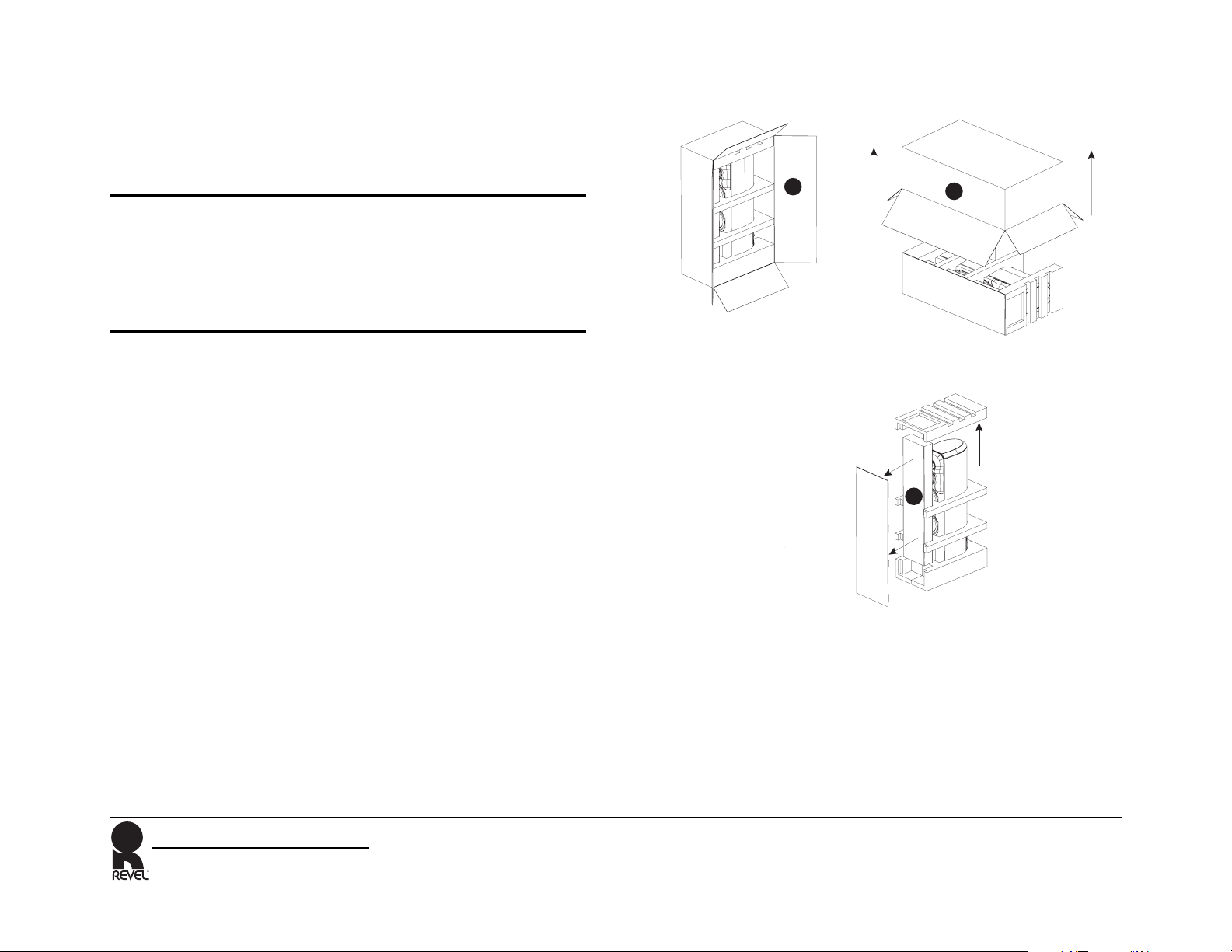
6. Tilt the cabinet forward and remove the bottom pad, using
caution to avoid touching the tweeter or midrange, Figure 1,
Step 3.
7. Carefully remove the tape from the red protective tweeter
cover.
Caution
Use caution not to touch or allow any object or liquid to come
in contact with the Beryllium tweeter dome. Variations in its
finish are normal. Any attempt to clean the tweeter dome will
result in damage, which is not covered under the limited
warranty.
8. We recommend installing the spikes/glides after determining
final speaker placement. Refer to the “Combination spikes/
glides” section or more info.
After unpacking the unit, carefully inspect the contents. If you
discover any damage, immediately contact your Revel dealer for
further assistance. To move an unpacked loudspeaker, rock it
side-to-side into place, using caution to avoid touching the
tweeter and midrange.
Keep all packing materials for future shipping.
Figure 1: Unpacking Instructions
2
1
2
3
In the unlikely event a product will need repair. Revel will only
accept a unit in its original shipping carton. Using any other
packing materials may result in damage to the product and will
void the warranty. See Service Information for additional details.
Ultima Salon2/Studio2
Owner’s Manual
5
Page 8

LOUDSPEAKER OVERVIEW
SALON2 DRIVER COMPLEMENT
The cabinet’s wood veneer finish does not require routine
maintenance. Cabinet surfaces that have been marked with
dust, fingerprints, or other dirt can be cleaned using a soft cloth
and high-quality wax.
The numbers in Figure 2 on the next page correspond with the
numbered items below.
1. (1) 1-inch (25mm) Beryllium tweeter
2. (1) 4-inch (102mm) midrange
3. (1) 6.5-inch (165mm) mid-woofer
4. (3) 8-inch (203mm) woofers
STUDIO2 DRIVER COMPLEMENT
The numbers in Figure 3 on the next page correspond with the
numbered items below.
1. (1) 1-inch (25mm) Beryllium tweeter
2. (1) 5.5-inch (140mm) midrange
3. (2) 8-inch (203mm) woofers
CABINET
The Revel Salon2/Studio2 Loudspeakers exemplify subtle
elegance with their smooth, rounded shapes, which easily blend
in with a wide variety of decors. Available in either a high-gloss
mahogany veneer or a high-gloss black finish, the Salon2/
Studio2 Series Loudspeakers will be a welcome compliment to
any home. The Salon2/Studio2 reduces cabinet-induced
colorations with 1-inch (25mm) thick walls and extensive
internal bracing. Adjustable combination spikes/glides can be
attached to the bottom of the cabinet stands for optimal stability,
accommodating installations on tile, hardwood, and carpeted
floors.
• To clean the cabinet, apply furniture polish to a soft cloth
then use the cloth to lightly wipe the cabinet surface. Use
care to avoid coming into contact with the tweeter dome or
any of the other drivers.
• To clean the grille, gently vacuum using a soft-bristled
brush vacuum attachment.
Caution
Use caution not to touch or allow any object or liquid to come
in contact with the Beryllium tweeter dome. Variations in its
finish are normal. Any attempt to clean the tweeter dome will
result in damage which is not covered under the limited
warranty. To prevent cabinet damage, do not use a cloth made
with steel wool or metal polish to clean the cabinet. To prevent
possible transducer damage, do not apply furniture polish
directly to the cabinet or tranducers.
REAR DOOR PANEL
The Salon2/Studio2 comes with a pre-installed rear panel door.
To connect a speaker cable:
• Open the door by pressing the “finger berm” on the left side
of the door.
• Determine the rear panel configuration that is suitable for
your installation and attach the speaker cable. (Refer to the
“Making Connections” section for more information.)
• Align the cable so that it fits within the center bottom
channel of the door.
• Close the door by pressing on the “finger berm” on the left
side of the door. Ensure that the door closes completely, and
does not crimp or jam on any of the cables.
6
Ultima Salon2/Studio2
Owner’s Manual
Page 9
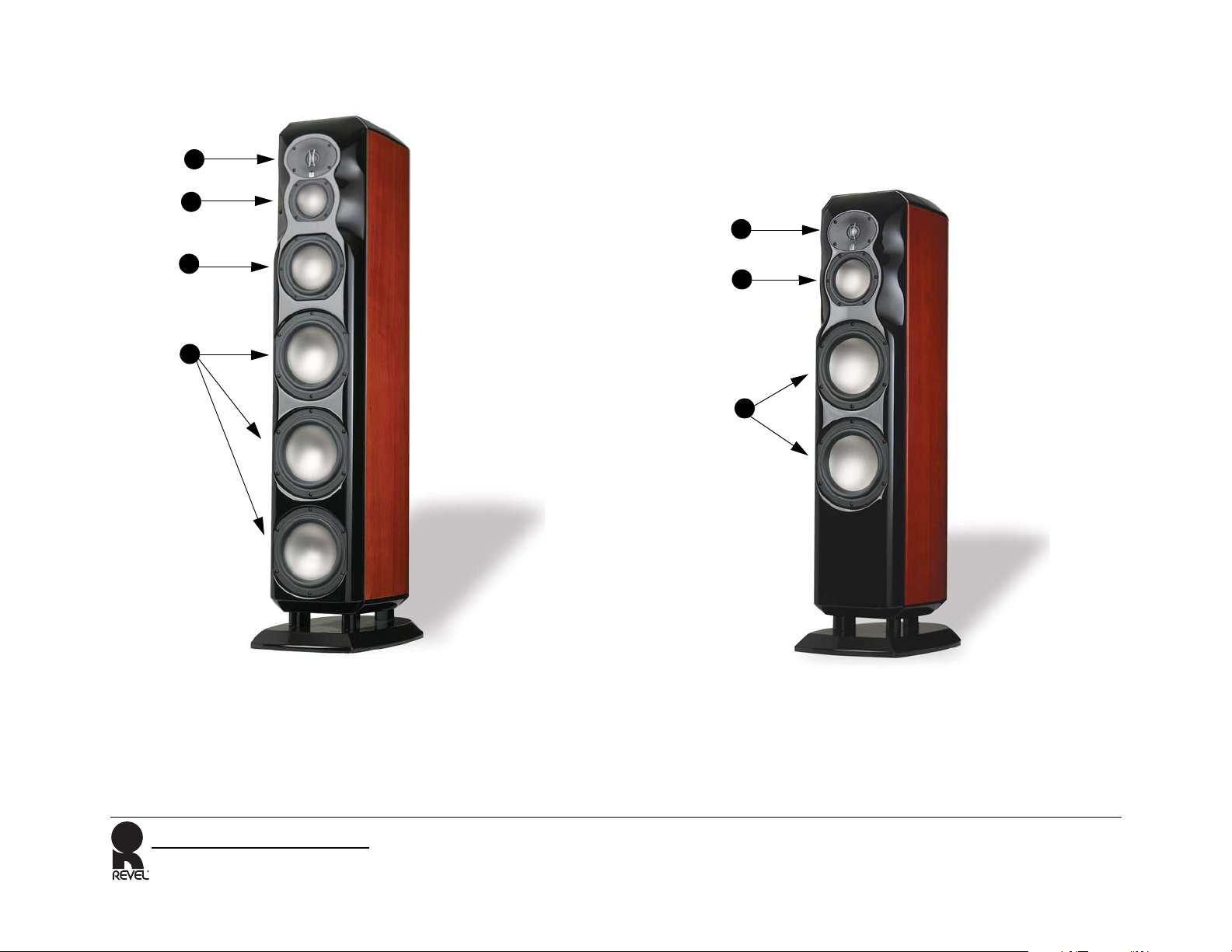
Figure 2: Salon2 Loudspeaker Figure 3: Studio2 Loudspeaker
1
1
2
1
1
3
1
4
2
3
Ultima Salon2/Studio2
Owner’s Manual
7
Page 10

FILTER NETWORK
The Salon2/Studio2 Loudspeakers utilize high-order networks
which optimize both the on-axis and off-axis response. These
sophisticated networks help to ensure smooth octave-to-octave
balance and timbral accuracy. Separate woofer, mid-woofer
(Salon2 only), midrange and tweeter filter boards prevent
mutual interference between filter network components,
dramatically reducing distortion over a wide dynamic range.
Gold-plated binding posts and shorting straps accommodate
single-wired, bi-wired, and bi-amplified connections. Low
Frequency Compensation and Tweeter Level switches on the rear
panel provide the ability to compensate for acoustic effects due to
various applications and loudspeaker placement, as well as
less-than-ideal listening room acoustics.
REAR PANEL OVERVIEW
Controls are provided on the rear panel which allow the
optimization of the Salon2/Studio2 Loudspeaker response for
different loudspeaker applications and placement. Refer to the
“Loudspeaker Placement” section for more information. The
definitions below refer to Figure 4, Rear Panel on the following
page.
1. Low Frequency Compensation Switch
• Select the Normal setting if the loudspeaker is located at
least 3 feet (.91m) from walls and other large objects.
• Select the Contour setting to help compensate for
challenging room acoustics due to particularly severe
stand waves.
2. Tweeter Level (dB) Switch
The tweeter output level can be adjusted in calibrated steps by
-1, -0.5, 0, +0.5 or +1 dB.
Note
Refer to the “Optimizing Performance” section for more information
about the Low Frequency Compensation and Tweeter Level switches.
3. Input Terminals
Provides high and low-frequency connections from the
associated power amplifier(s). One pair of high-frequency
and one pair of low-frequency gold-plated binding posts are
available. The input terminals can be configured for
single-wired, bi-wired, or bi-amplified connections. Refer to
the “Making Connections” section for additional
information.
4. Jumper Straps
Accommodates single-wired, bi-wired, and bi-amplified
connections. Two gold-plated jumper straps are installed for
single-wired connections. The jumper straps must be
removed when the input terminals are used for bi-wired or
bi-amplified connections. Refer to the “Making Connections”
section for additional information.
• Select the Boundary setting if the loudspeaker is built
into an entertainment center or shelving unit or if the
loudspeaker is located less than 2 feet (0.61m) from walls
or other large objects.
8
Ultima Salon2/Studio2
Owner’s Manual
Page 11

Figure 4: Rear Panel
Normal
1
Contour
2
Input Panel
Boundary
3
4
3
1. Low Frequency Compensation Switch
2. Tweeter Level (dB) Switch
Ultima Salon2/Studio2
Owner’s Manual
3
4
3
3. Input Terminals (- Negative, + Positive)
4. Jumper Straps
9
Page 12

INSTALLATION CONSIDERATIONS
Loudspeaker fidelity depends on the following three factors:
1. Loudspeaker accuracy
2. Loudspeaker placement
3. Listening room acoustics
LOUDSPEAKER ACCURACY
The advanced Ultima2 design features allow the Salon2/Studio2
to achieve exceptional acoustical precision. Each Salon2/Studio2
is hand-tuned during manufacturing to match the production
reference standard within a fraction of a decibel, ensuring
incomparable loudspeaker-to-loudspeaker consistency. As a
result, experimenting with loudspeaker placement and listening
room acoustics have the most significant impact on the
performance of the Salon2/Studio2 loudspeaker.
LOUDSPEAKER PLACEMENT
The bulleted items below identify important loudspeaker
placement considerations for the Salon2/Studio2.
• Remove all obstructions between the speakers and the
primary listening position. For instance, a coffee table
between the speakers and the primary listening position will
degrade imaging and timbre. Placing the speakers near large
objects may also cause unwanted reflections. The Low
Frequency Compensation switch can be used to optimize the
loudspeakers performance for the loudspeaker placement
options described in this section.
• For the best stereo imaging, place the loudspeakers at equal
distances from the primary listening position and the side
walls as shown in Figure 5.
Figure 5: Loudspeaker Placement
Primary Listening Position (Couch)
Acoustic Treatment Materials
• For optimal imaging and timbre, point the speaker directly
toward the primary listening position as shown in Figure 5.
The toe-in angle can be reduced to widen the soundstage,
even to the point at which the loudspeakers are pointing
straight forward. (Figure 5 is not a representation of the
recommended toe-in angle.)
• Move the loudspeakers farther from the front and side
listening room walls to improve stereo imaging and the sense
of spaciousness in the listening space.
• Move the loudspeakers closer to the corners or walls of the
listening room to increase bass response.
10
Ultima Salon2/Studio2
Owner’s Manual
Page 13

• The Salon2/Studio2 is magnetically shielded to minimize any
effect on CRT video monitors. However, small, stray magnetic
fields may affect large CRT monitors located in close
proximity to the Salon2/Studio2. These magnetic fields
decrease rapidly with distance, so moving the loudspeakers
farther away from the monitor will reduce interference. It is
important to confirm that the Salon2/Studio2 is suitable for
use with the intended CRT monitor.
.
Note
DLP, LCD, LCoS and Plasma display devices are not affected by
magnetic fields.
Caution
Loudspeakers placed on stands or video monitors may fall if
tipped or improperly positioned. To avoid this, anchor the
loudspeaker and stand using the same procedures and
hardware used to anchor bookcases, wall units, and other
furniture. Harman Specialty Group assumes no responsibility
for proper selection and installation of hardware or for any
personal injuries or product damages resulting from improper
installation or a fallen loudspeaker.
LISTENING ROOM ACOUSTICS
Listening rooms have a profound impact on sound, particularly
at lower frequencies. In fact, listening rooms can dominate the
sounds below about 400 Hz. Ideally, listening rooms would have
optimized dimensions to minimize the effects of room resonances.
But in reality, most listening rooms are not designed to enhance
loudspeaker performance.
The interaction between loudspeakers and listening rooms is
complex, depending on two important determinants that affect
the loudspeaker and the listener.
1. Surfaces and other boundaries often cause large peaks and
dips in low-frequency response. These peaks and dips often
reach ranges of 12 dB or more.
2. Standing waves (also known as room modes or resonances)
interact with both the loudspeaker and the listener locations,
resulting in large frequency response errors.
Unfortunately, there is no simple solution that considers both
factors. Even computer software programs that examine one or
both factors may not calculate proper primary listening position
or loudspeaker placement values.
In most cases, proper selection of the primary listening position
combined with proper placement of the loudspeaker will result in
superior performance at lower frequencies. The difference
between superior and inferior results is often just a small
adjustment of the primary listening position or loudspeaker
placement. For more information or assistance contact an
authorized Revel dealer.
Ultima Salon2/Studio2
Owner’s Manual
11
Page 14

ACOUSTIC TREATMENT MATERIALS
COMBINATION SPIKES/GLIDES
As previously mentioned, the Salon2/Studio2 Loudspeakers
utilize high-order networks which optimize both the on-axis and
off-axis response. Their optimized response minimizes sonic
degradation that can occur in overly “live” rooms. Placing
minimal acoustic treatment materials at primary reflection
points will reduce these distortions even further. Ideally, acoustic
absorbers should be placed at the first reflection points on the
front and side walls and either acoustic absorbers or diffusers
should be placed at the first reflection points on the rear wall.
Because the listener’s eyes and ears are on the same plane, the
“mirror method” is an accurate determinant of critical reflection
points. This method can be used to determine reflection points
for side walls, rear walls, front walls, and even the ceiling.
Applying acoustic treatment materials to the side walls is most
important, followed by the front wall, rear wall, and ceiling.
To determine reflection points using the mirror method:
1. Once the Loudspeakers has been placed, sit in the primary
listening position and ask another person to slide a mirror
along the listening room walls.
2. Note the locations at which the person sitting in the primary
listening position can see either the left, center or right front
loudspeakers. Be sure to look for all of the speakers in the
reflection on each room boundaries, including the front and
rear walls. These are reflection points that require acoustic
treatment materials.
If acoustic treatment materials are not available, hanging a rug
over the reflection points will help reduce degradation in overly
“live” rooms. Carpeting the floor between the loudspeakers and
the primary listening position and placing irregular surfaces
such as bookcases at first reflection points will also help
minimize strong reflections. Avoid placing large reflective
surfaces such as coffee tables between the loudspeakers and the
listeners for critical listening.
When shipped, combination spikes/glides, shown in the next
page in Figure 6 and 7, are not attached to the bottom of the
cabinet. For optimal stability and to accommodate installations
on tile, hardwood, and carpeted floors, you can install the
combination spikes/glides. Use the glide side to protect tile and
hardwood floors.
Caution
When moving the Salon or Studio2, avoid dragging it across
the floor. If the Salon2 or Studio2 are placed on a carpeted
floor, the spikes/glides should be adjusted with the sharp end
protruding from the cabinet.
The spikes/glides should be used so that the smooth
“glide” end is exposed to protect tile, hardwood floors and
furniture.
To install the combination spikes/glides:
1. Place the speaker on its side on a soft towel or carpeted floor.
2. Select the appropriate end of the spike/glide, depending on
your surface. If the speaker is to be used on a hardwood floor
or smooth surface, use the glide end of the spike.
3. Locate the four threaded insets on the bottom of the speaker.
4. Screw the first spike into the threaded insert, making sure to
include the locking ring and felt washer in the order shown.
5. Repeat step 4 for the remaining three spikes. Make sure all
spikes are evenly threaded to achieve a level balance.
12
Ultima Salon2/Studio2
Owner’s Manual
Page 15

Figure 6: Combination Spike/Glide Components
MAKING CONNECTIONS
Felt Washer
Locking Ring
(Spike End Down)
Spike
Figure 7: Combination Spike/Glide Options
Spike End Down Glide End Down
The Salon2/Studio2 features gold-plated binding posts and
jumper straps that allow it to be configured for single-wired,
Bi-wired, or Bi-amplified connections.
Caution
Never make or break connections unless all system
components are powered off.
Remove the input panel jumper-straps identified in Figure 4,
page 9, before making bi-wired or bi-amplified connections.
Failure to do so may cause damage to some power amplifiers.
Before making connections, note the following:
• The standard connection method uses a single loudspeaker
cable. The Salon2/Studio2 are equipped with two pairs of
input terminals to allow for bi-wiring or bi-amplification.
While Revel does not endorse one particular connection
method over another, these additional connection options are
available if desired. The design of this loudspeaker is such
that optimal performance can be attained using the standard
connection method.
• Make all connections observing the proper polarity,
positive-to-positive (+) and negative-to-negative (-).
Connections that do not observe the proper polarity will
cause poor stereo imaging and diminished bass response.
• Use high-quality loudspeaker cable with a maximum total
loop resistance of 0.07 Ohms or less (for each wire run). Refer
to the following table to determine the appropriate wire
gauge.
Ultima Salon2/Studio2
Owner’s Manual
13
Page 16

Minimum Wire Gauge
Gauge
(AWG)
68727
76921
85818
94313
10 34 10
11 27 8
12 22 7
13 17 5
14 14 4
15 11 3
Length
(Feet)
Length
(Meters)
• Vertical bi-amplified connections must be made with
identical power amplifiers. Horizontal bi-amplified
connections can be made with identical or non-identical
power amplifiers with identical gain factors.
• When making bi-amplified connections, both power
amplifiers must receive identical input signals from the
associated preamplifier. A “Y” adaptor is required if the
associated preamplifier does not offer two connectors per
output channel. Otherwise, each power amplifier can be
connected to a separate connector for the same output
channel of the preamplifier.
• If desired, contact an authorized Revel dealer for information
about the suitability of power amplifier components before
connecting the Salon2/Studio2 to the associated power
amplifier.
• Review the owner’s manuals for associated audio
components to determine their connection procedures.
16 9 3
17 7 2
18 5 2
Note
High loop resistances that exceed 0.07 Ohms (for each wire run) will
cause the filter network to be mis-terminated, resulting in
considerable degradation of sound quality.
14
Ultima Salon2/Studio2
Owner’s Manual
Page 17

SINGLE WIRE CONNECTIONS
Figure 8: Single-Wired Connections
Single-wired connections are the most common. These are made
between one pair of the Salon2/Studio2 input terminals and one
power amplifier output channel as shown in Figure 8.
To make single-wired connections:
1. Connect one pair of loudspeaker wires to the desired Salon2/
Studio2 input terminals. Then connect the same pair of
loudspeaker wires to the desired power amplifier output channel. (The high frequency input terminals are recommended).
2. Make sure that all terminals are firmly hand-tightened.
Contour
Normal
STUDIO2
POWER
AMPLIFIER
Boundary
Ultima Salon2/Studio2
Owner’s Manual
OUTPUT
15
Page 18

BI-WIRED CONNECTIONS
Figure 9: Bi-Wired Connections
Bi-wired connections are made between both pairs of the Salon2/
Studio2 input terminals and one power amplifier output channel
as shown in Figure 9.
To make bi-wired connections:
1. Remove the jumper straps identified in Figure 4, page 9.
2. Connect one pair of loudspeaker wires to the high-frequency
of Salon2/Studio2 input terminals. Then connect the same
pair of loudspeaker wires to the desired power amplifier
output channel.
3. Connect another pair of loudspeaker wires to the low-
frequency pair of Salon2/Studio2 input terminals. Then
connect the loudspeakers to the same power amplifier output
channel that was selected in Step 2.
4. Make sure that all terminals are firmly hand-tightened.
Normal
STUDIO2
POWER
AMPLIFIER
Contour
Boundary
16
OUTPUT
Ultima Salon2/Studio2
Owner’s Manual
Page 19

VERTICAL BI-AMPLIFIED CONNECTIONS
Figure 10: Vertical Bi-Amplified Connection
Vertical bi-amplified connections are made between both pairs of
Salon2/Studio2 input terminals and two separate power amplifier
output channels. Each speaker is connected to its own power
amplifier. The power amplifiers must be identical. Vertical
bi-amplified connections are shown in Figure 10.
Note
When making vertical bi-amplified connections, both power
amplifiers must receive identical input signals from the associated
preamplifier. A “Y” adaptor is required if the associated preamplifier
does not offer two connectors per output channel. Otherwise, each
power amplifier can be connected to a separate connector for the
same output channel of the preamplifier.
To make vertical bi-amplified connections:
1. Remove the jumper straps identified in Figure 4, page 9.
2. Connect one pair of loudspeaker wires to the high frequency
pair of Salon2/Studio2 input terminals. Then connect the
same pair of loudspeaker wires to the desired power amplifier
output channel.
3. Connect another pair of loudspeaker wires to the
low-frequency pair of Salon2/Studio2 input terminals. Then
connect the same pair of loudspeaker wires to a separate
output channel on the same power amplifier.
Normal
STUDIO2
POWER
AMPLIFIER 1
Contour
Boundary
4. Make sure that all terminals are firmly hand-tightened.
Note
Vertical bi-amplified connections must be made using two identical
power amplifiers.
Ultima Salon2/Studio2
Owner’s Manual
OUTPUT 2
OUTPUT 1
17
Page 20

HORIZONTAL BI-AMPLIFIED CONNECTIONS
Horizontal bi-amplified connections are made between both
pairs of Salon2/Studio2 terminals and two separate output
channels on two separate power amplifiers. The high-frequency
pair of Salon2/Studio2 input terminals are connected to one
power amplifier, while the low-frequency pair are connected to
another power amplifier.
These power amplifiers can be identical or non-identical, but
must have identical gain factors. If the gain factors are not
identical, a means of adjusting the input level of at least one
power amplifier is required. Horizontal bi-amplified connections
are shown in Figure 11.
Note
When making horizontal bi-amplified connections, both power
amplifiers must receive identical input signals from the associated
preamplifier. A “y” adaptor is required if the associated preamplifier
does not offer two connectors per output channel. Otherwise, each
power amplifier can be connected to a separate connector for the
same output channel of the preamplifier.
Horizontal bi-amplified connections can be made using identical or
non-identical power amplifiers. However, these power amplifiers
must have identical gain factors. If the gain factors are not
identical, a means of adjusting the input level of at least one power
amplifier is required. Contact an authorized Revel dealer for
assistance.
3. Connect another pair of loudspeaker wires to the
low-frequency Salon2/Studio2 terminals. Then connect the
same pair of loudspeaker wires to the desired output channel
on another power amplifier.
4. Make sure that all terminals are firmly hand-tightened.
Figure 11: Horizontal Bi-Amplified Connections
Contour
Boundary
Normal
STUDIO2
POWER
AMPLIFIER 1
POWER
AMPLIFIER 2
To make horizontal bi-amplified connections:
1. Remove the jumper straps identified in Figure 4, page 9.
2. Connect one pair of loudspeaker wires to the high-frequency
pair of Salon2/Studio2 input terminals then connect the
same pair of loudspeaker wires to the desired power amplifier
output channel.
18
OUTPUT 1
OUTPUT 1
Ultima Salon2/Studio2
Owner’s Manual
Page 21

OPTIMIZING PERFORMANCE
“Loudspeaker Placement” section for additional information
about loudspeaker placement.
To optimize the Salon2/Studio2 for best performance:
1. When the Salon2/Studio2 is connected, begin with the
Tweeter Level Switch set to 0. (Different listening rooms may
require other High Frequency Level switch settings.)
2. Set the Low Frequency Compensation Switch to correspond
with the Salon2/Studio2 placement. This is the best starting
point, and will typically result in the most neutral sound for a
given application. If the Salon2/Studio2 sounds either too
“thick” or too “thin,” especially when reproducing male
voices, experiment with other Low Frequency Compensation
Switch settings. In any case, it is worth experimenting to find
the best switch setting for the particular installation. Note
that the bass level will decrease as the Low Frequency
Compensation switch is turned clockwise.
• Select the Normal setting if the loudspeaker is located at
least 3 feet (.91m) from walls and other large objects.
• Select the Contour setting to help compensate for
challenging room acoustics due to particularly severe
stand waves. Try this setting if the bass is “boomy” or
“ill-defined.”
• Select the Boundary setting if the loudspeaker is built
into an entertainment center or shelving unit or if the
loudspeaker is located less than 2 feet (0.61m) from walls
or other large objects.
6. If desired, experiment with the Low Frequency Compensation
switch and the Tweeter Level switch to optimize the system for
the room acoustics.
Note
Rotating the Low Frequency Compensation Switch clockwise
decreases low-frequency output.
Note
Please be sure to mute the system volume level before adjusting any
switch settings.
3. Listen to a variety of high quality material, making sure to
include vocal recordings. If the Salon2/Studio2 Loudspeakers
are part of a multichannel system, switch the associated
controller to a “two-channel” or “stereo” mode.
4. Listen from the primary listening position, increasing volume
to a comfortable level.
5. Experiment with the Salon2/Studio2 placement to achieve the
best overall tonal balance and image precision. Refer to the
Ultima Salon2/Studio2
Owner’s Manual
19
Page 22

LOUDSPEAKER VOLUME LEVEL
High-order filters include steep cut-offs to reduce potential
damage from “out-of-band” frequencies. Combined with
carefully designed transducers and filter networks, this approach
helps the Salon2/Studio2 to maintain its performance under
extreme operating conditions.
However, all loudspeakers have limits when it comes to
continuous playback. To extend these limits, avoid playback at
volume levels that distort or sound “strained”.
Caution
To avoid damage, reduce volume level immediately if
loudspeaker sound is not clean and clear.
20
Ultima Salon2/Studio2
Owner’s Manual
Page 23

SPECIFICATIONS
SALON2 SPECIFICATIONS
Specifications Value Definition
Sensitivity 86.4 dB SPL with 2.83 V @ 1m (2 π
anechoic)
Impedance 6.0 Ω (nominal)
3.7 Ω (minimum)
Filter Network Four-way, high-order acoustic response @
Frequency Range - 3 dB from 23 Hz to 45 kHz Describes the low frequency and high frequency at which the loudspeaker
In-Room Response Relative to
Target Response
150 Hz, 575 Hz and 2.3 kHz
±0.5 dB from 29 Hz to 18 kHz Indicates sound quality in context with other specifications. A breakthrough
Indicates the amount of power the associated power amplifier must deliver to
drive the loudspeaker at reasonable volume levels. Conservatively rated
specifications indicate high sensitivity, meaning that a massive power
amplifier is not required to drive Revel loudspeakers to reasonable volume
levels in large listening spaces.
Indicates whether the loudspeaker presents a “difficult” or “easy” load on the
associated power amplifier. Combined with moderate phase angles, a
minimal impedance specification of 3.7 Ω allows a reasonably designed
power amplifier to drive Revel loudspeakers.
Indicates the acoustical characteristics of the filter network. Steep filters
indicate an optimized filter network that produces minimal acoustical
interference, low distortion, and expansive dynamic range.
system amplitude response is 3 dB lower than the average level, when
measured in a 4 π anechoic chamber. While the -3 dB frequencies are the
industry standard for specifying frequency range, Low Frequency Extension is
a more useful specification for comparing the low-bass output capabilities of
loudspeakers.
measurement, this specification closely correlates to sound quality in a single
curve—a long-standing goal of loudspeaker engineers. In-room response is
measured through the use of large anechoic chambers. The loudspeaker’s
response is measured every 10 degrees, horizontally and vertically, for a total
of 72 response measurements. The in-room response curve is a prediction of
how the loudspeaker would measure in a typical room. Research and
observation reveals that ubiquitous on-axis response curves cannot
distinguish between two loudspeakers with radically different sound qualities.
Ultima Salon2/Studio2
Owner’s Manual
21
Page 24

SPECIFICATIONS
SALON2 SPECIFICATIONS
Specifications Value Definition
Listening Window Response ±1.0 dB from 26 Hz to 20 kHz Indicates the on-axis response of the loudspeaker. An improved on-axis
Low-Frequency Extension -10 dB at 17 Hz
-6 dB at 20 Hz
-3 dB at 23 Hz
measurement, this specification reduces the visual confusion of inaudible
interference. It retains full accuracy without using “spectral smoothing,”
which results in significant data loss.
Indicates the low-frequency response of the loudspeaker. Studies have shown
that the –10 dB specification best correlates to controlled listening tests. At low
frequencies, most loudspeaker and listening room combinations demonstrate
significant room gain, which produces an increase in levels as frequencies
decrease. Unlike the –3 dB specification, the –10 dB specification reflects the
steepness of low-frequency roll-offs.
22
Ultima Salon2/Studio2
Owner’s Manual
Page 25

STUDIO2 SPECIFICATIONS
Specifications Value Definition
Sensitivity 87.7 dB SPL with 2.83 V @ 1m (2 π
anechoic)
Impedance 6.0 Ω (nominal),
3.7 Ω (minimum @ 90 Hz)
Filter Network Three-way, high-order acoustic response
@ 230 Hz and 2 kHz
Frequency Range - 3dB from 32 Hz to 45 kHz Describes the low frequency and high frequency at which the loudspeaker
In-Room Response Relative to
Target Response
±0.5 dB from 31 Hz to 18 kHz Indicates sound quality in context with other specifications. A breakthrough
Indicates the amount of power the associated power amplifier must deliver to
drive the loudspeaker at reasonable volume levels. Conservatively-rated
specifications indicate high sensitivity, meaning that a massive power
amplifier is not required to drive Revel loudspeakers to reasonable volume
levels in large listening spaces.
Indicates whether the loudspeaker presents a “difficult” or “easy” load on the
associated power amplifier. Combined with moderate phase angles, a
minimal impedance specification of 3.7 Ω allows a reasonably designed
power amplifier to drive Revel loudspeakers.
Indicates the acoustical characteristics of the filter network. Steep filters
indicate an optimized filter network that produces minimal acoustical
interference, low distortion, and expansive dynamic range.
system amplitude response is 3 dB lower than the average level, when
measured in a 4 π anechoic chamber. While the -3 dB frequencies are the
industry standard for specifying frequency range, Low Frequency Extension is
a more useful specification for comparing the low-bass output capabilities of
loudspeakers
measurement, this specification closely correlates to sound quality in a single
curve—a long-standing goal of loudspeaker engineers. In-room response is
measured through the use of large anechoic chambers. The loudspeaker’s
response is measured every 10 degrees, horizontally and vertically, for a total
of 72 response measurements. The in-room response curve is a prediction of
how the loudspeaker would measure in a typical room. Research and
observation reveals that ubiquitous on-axis response curves cannot distinguish between two loudspeakers with radically different sound qualities.
Listening Window Response ±1.0 dB from 33 Hz to 20 kHz Indicates the on-axis response of the loudspeaker. An improved on-axis
measurement, this specification reduces the visual confusion of inaudible
interference. It retains full accuracy without using “spectral smoothing,”
which results in significant data loss.
Ultima Salon2/Studio2
Owner’s Manual
23
Page 26

Specifications Value Definition
Low-Frequency Extension -10 dB at 21 Hz
-6 dB at 25 Hz
-3 dB at 32 Hz
.
Note
Specifications are subject to change without notice.
Indicates the low-frequency response of the loudspeaker. Studies have shown
that the –10dB specification best correlates to controlled listening tests. At low
frequencies, most loudspeaker and listening room combinations demonstrate
significant room gain, which produces an increase in levels as frequencies
decrease. Unlike the –3 dB specification, the –10dB specification reflects the
steepness of low-frequency roll-offs.
24
Ultima Salon2/Studio2
Owner’s Manual
Page 27

Salon2 Dimensions
Studio2 Dimensions
Shipping Weight: 178 Pounds (80.7 kg)
11 inches
(279 mm)
(1352 mm)
53.25 inches
54.53 inches
(1185 mm)
INCHES
MM
INCHES
MM
INCHES
MM
Shipping Weight: 140 Pounds (63.5 kg)
10.75 inches
(273 mm)
(1207 mm)
47.53 inches
17.74 inches
(451 mm)
16.59 inches
(421 mm)
14.09 inches
(645 mm)
14 inches
(356 mm)
Ultima Salon2/Studio2
Owner’s Manual
INCHES
MM
(1175 mm)
46.25 inches
13.75 inches
(349 mm)
20.5 inches
(521 mm)
25
Page 28

OBTAINING SERVICE
Product Shipment Directions:
To obtain warranty or non-warranty service, contact an
authorized Revel dealer.
Before returning a loudspeaker for warranty or
non-warranty service, contact Harman Specialty Group
Customer Service to determine the extent of the problem
and to obtain a Return Material Authorization (RMA)
number. No loudspeakers will be accepted without an RMA
number issued from Harman Specialty Group.
If a Revel loudspeaker must be returned for repair, Harman
Specialty Group will assume no responsibility for the loudspeaker
during shipment from the customer to Harman Specialty Group,
whether the loudspeaker is or is not covered under warranty.
To contact Harman Specialty Group Customer Service:
Telephone: 781-280-0300
Service Fax: 781-280-0499
Sales Fax: 781-280-0495
www.revelspeakers.com
All Returns must be:
The following information must be included when a
loudspeaker is returned for service:
•Name
• Company name
• Street address, city, state and, zip code
• Telephone number including area code and country code (if
applicable)
• Loudspeaker serial number
• A detailed description of the problem
• The preferred method of return shipment
• RMA number clearly marked on both the inside and outside
of the package
Do not return accessories such as owner’s manuals unless
instructed to do so.
Product Shipments:
HSG/Revel Returns Dept.
RMA #
801 S. 75th Avenue
Phoenix, AZ 85043
• Well-packaged using the original packing materials
• Properly insured and consigned
• Pre-paid to a reliable shipping agent
26
Ultima Salon2/Studio2
Owner’s Manual
Page 29

LIMITED WARRANTY
A valid serial number is required for
warranty coverage. This Revel warranty
protects the original retail purchaser for a
period of five (5) years (parts and labor) from
any failure as a result of original
manufacturing defects so long as:
1. The Revel products were purchased
within the 50 United States, its
territories, or Canada
2. The dealer from whom the Revel
products were purchased was authorized
to sell such products at the time of the
original purchase.
3. The original, dated Bill of Sale is
presented whenever service is required
during the warranty period.
The balance of this warranty is transferable
only if the used product is purchased from an
authorized Revel dealer. This warranty is
only valid for service within the United
States, its territories, and Canada, please
contact an authorized Revel dealer for
warranty and service information.
Any Revel product not performing
satisfactorily may be returned to the factory
for evaluation. Return authorization must
first be obtained by either calling or writing
Customer Service prior to shipping the
product. The customer is responsible for
shipping charges to the factory. Customer
Service will pay return shipping charges
within the United States only in the event
that the product is found to be defective as
mentioned above. There are other
stipulations that may apply to shipping
charges.
There is no other express warranty on this
product. Neither this warranty nor any other
warranty, express or implied, including
implied warranties of merchantability and
fitness, shall extend beyond the warranty
period. No responsibility is assumed for any
incidental or consequential damages, so that
the above exclusion or limitation may not
apply.
This warranty provides specific legal rights.
Other states may provide additional rights.
This warranty is applicable in the United
States, its territories, and Canada. Outside of
the United States, its territories, and Canada,
please contact an authorized Revel dealer for
warranty and service information.
The information this document contains is
subject to change without notice. In the event
that there are differences between this
warranty and the provisions of any
advertisements, documentation, product
brochures, or packaging cartons, the terms of
this warranty will prevail.
Harman Specialty Group
3 Oak Park Drive
Bedford, MA 01730-1413
USA
Tel 781-280-0300
Fax 781-280-0490
www.revelspeakers.com
Customer Service
Tel 781-280-0300
Fax 781-280-0495 (Sales)
Fax 781-280-0499 (Service)
Page 30

Harman Specialty Group, 3 Oak Park Drive, Bedford, MA, 01730-1413 USA | Telephone: 781-280-0300 | Fax: 781-280-0490
Customer Service Telephone: 781-280-0300 | Sales Fax: 781-280-0495 | Service Fax: 781-280-0499
Product Shipments: HSG/Revel, Returns Dept., 801 S. 75th Avenue, Phoenix, AZ 85043 USA
| www.revelspeakers.com
Part No. 354898-001 | Rev 1 | 12/07
 Loading...