

Page 1

Revel®Ultima™Sub 30
®
Page 2

WARNING: TO REDUCE THE RISK OF FIRE OR ELECTRIC SHOCK,
DO NOT EXPOSE THIS PRODUCT TO RAIN OR MOISTURE.
REVEL ULTIMA SUB 30
Owner’s Manual
2
CAUTION
RISK OF ELECTRIC SHOCK
DO NOT OPEN
CAUTION: TO REDUCE THE RISK OF ELECTRIC SHOCK,
DO NOT REMOVE COVER (OR BACK).
NO USER-SERVICEABLE PARTS INSIDE.
REFER SERVICING TO QUALIFIED SERVICE PERSONNEL.
The lightning flash with arrowhead symbol, within an equilateral triangle, is intended to alert the user to the presence of
uninsulated “dangerous voltage” within the product’s enclosure
that may be of sufficient magnitude to constitute a risk of electric shock to persons.
The exclamation point within an equilateral triangle is
intended to alert the user to the presence of important operating and maintenance (servicing) instructions in the literature
accompanying the product.
Page 3
IMPORTANT SAFETY INSTRUCTIONS
Please read all instructions carefully and completely before
operating your REVEL
®
ULTIMA™SUB 30 powered subwoofer
system.
1. Always disconnect ac power before connecting or disconnecting
any cables, or when cleaning any component.
2. This product uses a three-conductor power cord, which
includes an earth-ground connection. To prevent shock hazard,
always connect it directly to a grounded outlet.
3. Never use any ac extension cord with this product.
4. Never use flammable or combustible chemicals for cleaning
audio components.
5. Never operate this product with any covers removed.
6. Never wet the inside of this product with any liquid.
7. Never pour or spill liquids directly onto this unit.
8. Never block air flow through ventilation slots or heatsinks.
9. Never bypass any fuse.
10. Never replace any fuse with a value or type other than specified.
11. Never attempt to repair this product yourself. If a problem
occurs, contact your Revel retailer.
12. Never expose this unit to extremely high or low temperatures.
13. Never operate this product in an explosive atmosphere.
14. Always keep electrical equipment out of the reach of children.
15. Always consider manual and safety instructions in any end
use application.
Before connecting this product to an ac power line, verify the voltage
shown in the voltage selector switch (on the rear panel) matches the ac
line voltage where the unit will be operated. Never attempt to operate
or connect this product to an ac line voltage that is different from the
one indicated in the voltage selector switch. Using a different setting
can damage the unit and will void your warranty!
REVEL ULTIMA SUB 30
Owner’s Manual
3
WARNING
Page 4

TABLE OF CONTENTS
INTRODUCTION.........................................................5
ABOUT THE MANUAL AND WARRANTY...................................................5
DESCRIPTION............................................................6
SUBWOOFER ......................................................................................6
AUXILIARY BASS RADIATOR......................................................................7
ELECTRONICS.....................................................................................7
CABINET.............................................................................................7
UNPACKING..............................................................8
INSPECTING THE REVEL ULTIMA SUB 30...............................................9
ADJUSTING THE SPIKE FEET ................................................................9
REAR PANEL LAYOUT...............................................10
CONNECTIONS........................................................12
APPLICATIONS.........................................................13
MULTI-CHANNEL CONTROLLER WITH CROSSOVER AND
A REVEL ULTIMA SUB 30................................................................14
MULTI-CHANNEL CONTROLLER WITH CROSSOVER AND
MULTIPLE REVEL ULTIMA SUB 30 SUBWOOFERS..............................15
MULTI-CHANNEL CONTROLLER AND
A REVEL ULTIMA SUB 30 WITH CROSSOVER....................................16
SURROUND-SOUND PROCESSOR WITH CROSSOVER AND
REVEL ULTIMA SUB 30 SUBWOOFERS IN STEREO.............................17
MULTI-CHANNEL CONTROLLER AND REVEL ULTIMA SUB 30
SUBWOOFERS WITH CROSSOVERS IN STEREO.................................. 18
STEREO POWER AMPLIFIER AND
A REVEL ULTIMA SUB 30 WITH CROSSOVER....................................19
MULTI-CHANNEL CONTROLLER AND MULTIPLE REVEL ULTIMA SUB 30
SUBWOOFERS WITH CROSSOVERS.....................................................20
STEREO POWER AMPLIFIER AND
A REVEL ULTIMA SUB 30 WITHOUT HIGH-PASS CROSSOVER.............21
SYSTEM OPTIMIZATION............................................22
PLACEMENT OVERVIEW.....................................................................22
GENERAL PLACEMENT GUIDELINES....................................................23
SOUND MEASUREMENT GUIDELINES...................................................25
SELECTING CROSSOVER POINTS AND SLOPES ....................................26
CABINET CARE........................................................27
TROUBLESHOOTING ................................................27
OBTAINING SERVICE................................................28
SPECIFICATIONS......................................................29
SUBWOOFER ....................................................................................29
AMPLIFIER........................................................................................29
REVEL ULTIMA SUB 30
Owner’s Manual
4
Page 5
INTRODUCTION
The REVEL ULTIMA SUB 30 powered subwoofer system
combines an outstanding 15" subwoofer with a 1,000-watt (rms)
amplifier, capable of 1,400-watt peaks, for stupendous bass output.
Moreover, the REVEL ULTIMA SUB 30’s stylistic form and
compact size provide a surprisingly prodigious output and unprecedented tonal accuracy, even in the deepest octaves. Impressive features include three independent parametric equalizers and an
adjustable crossover so you can customize and adapt this system for
a wide variety of applications.
This tremendous flexibility results in superb integration with any
Revel loudspeakers, or even with other manufacturers’ speakers.
ABOUT THE MANUAL AND WARRANTY
To begin enjoying your REVEL ULTIMA SUB 30, first read and
then perform the instructions in this owner’s manual. Maximum
performance is dependent on following all instructions described
here, as well as those found in the owner’s manuals of
associated components in your audio system. Save these instructions
for future reference.
The REVEL ULTIMA SUB 30 is covered by a limited warranty, so
save the bill of sale to protect your purchase and aid in any servicerelated questions.
REVEL ULTIMA SUB 30
Owner’s Manual
5
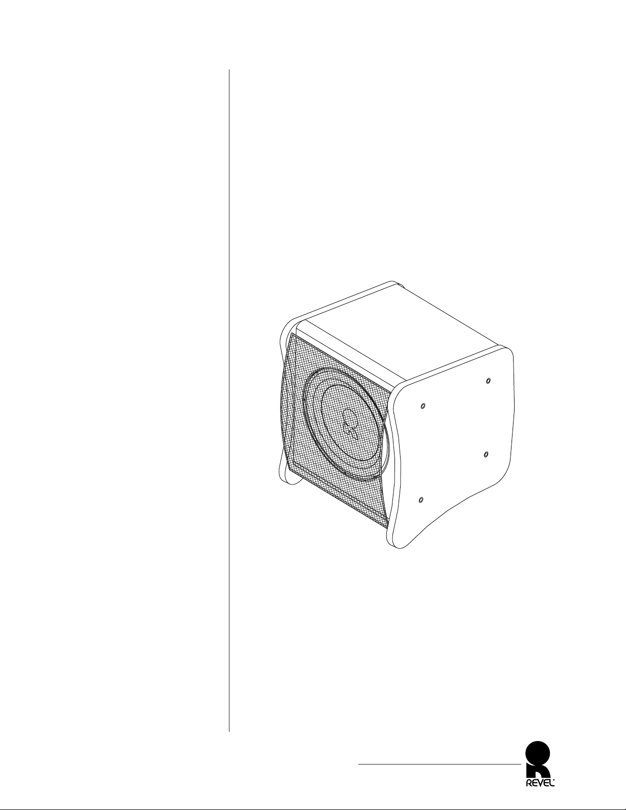
Figure 1.The REVEL
ULTIMA SUB 30
powered subwoofer system.
Page 6
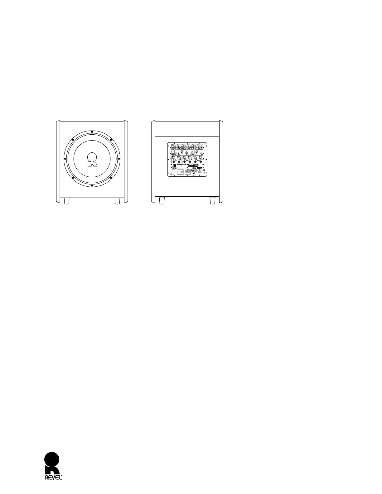
Figure 2. Transducer and connection locations for the REVEL
ULTIMA SUB 30 powered
subwoofer system.
DESCRIPTION
The REVEL ULTIMA SUB 30 powered subwoofer system features
a unique transducer that combines brute-force capabilities unprecedented in home loudspeakers with a new level of low frequency
nuance and refinement. Combined with the huge internal power
capability, the result is a new standard of bass performance and
adaptability for home entertainment systems.
SUBWOOFER
To ensure uncompressed dynamic range, each REVEL ULTIMA
SUB 30 features a subwoofer with the following attributes:
•A 3-inch (76 mm) diameter, four-layer voice coil with 23-gauge
copper wire is wound on a dual-laminated Kapton
®
former for
extraordinary power handling and freedom from compression.
•Extremely long-throw voice coil is capable of 2.5inches (64 mm)
of peak-to-peak linear excursion, and 3 inches (76 mm) of maximum excursion for uncompressed reproduction of deep sustained
bass notes.
•A massive, 130-ounce (3.7 kg) magnet system produces
1.4 tesla of flux in the gap.
•Ultra-rigid Kevlar
®
pulp and alloy composite cone with an
inverted metal dome operate as a perfect piston under all
reproduction conditions.
•Modulation rings and a machined “T” pole-piece for extremely
low distortion.
• The heavy-wall, cast-aluminum frame maintains alignment
between the magnet structure and the moving elements, while
offering excellent rigidity to eliminate basket resonances.
REVEL ULTIMA SUB 30
Owner’s Manual
6
3O
REVEL ULTIMA SUB 30
Front (without grille)
REVEL ULTIMA SUB 30
Rear
Page 7

AUXILIARY BASS RADIATOR
Each REVEL ULTIMA SUB 30 also includes an auxiliary bass radiator (on the cabinet bottom) with the following attributes:
• 15-inch (381 mm) cast frame
•Produces up to 2.2-inch (55.9 mm) peak-to-peak excursion that
serves to dramatically increase output at the lowest frequencies,
while reducing distortion
ELECTRONICS
Each REVEL ULTIMA SUB 30 contains an electronics section with
the following attributes:
• An extremely low-distortion, 1,000-watt (rms) amplifier with
1,400-watt burst capability produces peak bass output up to
126 dB at 30 Hz in a standard listening room.
•Inaudible protection circuit to guard against overload.
• Three independent parametric equalizers, each with variable frequency, bandwidth, and level controls, to allow you to precisely
tailor the room response and tame unwieldy acoustic anomalies.
• 2-way crossover with variable frequency and selectable slopes
allows ideal response matching with other audio components.
NOTE: For details on controls and connections, see “Rear Panel Layout”
on page 10.
CABINET
The REVEL ULTIMA SUB 30’s cabinet is constructed of 1-inch
(25 mm) thick MDF wall, optimally designed and internally braced
with the aid of laser interferometry, for unshakable performance.
REVEL ULTIMA SUB 30
Owner’s Manual
7
Page 8
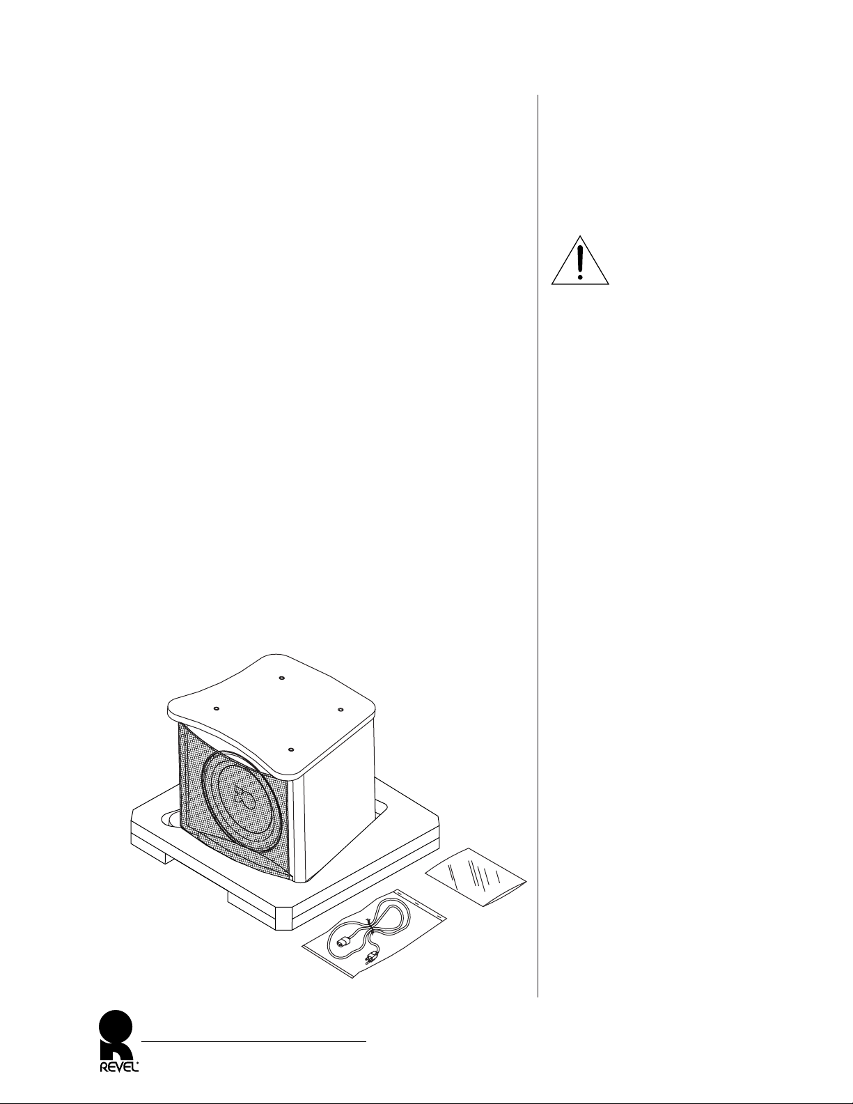
Figure 3.The REVEL ULTIMA
SUB 30 with its inner packing
materials.
UNP ACKING
To avoid personal injury and possible product damage, we strongly
urge you to enlist additional help before unpacking the REVEL
ULTIMA SUB 30. Also, be sure to obser ve the following precautions and procedures:
• Do not attempt to lift the product from its packing carton
alone. To unpack a product properly, at least two strong people
will be needed.
• To avoid injury, use extreme care during unpacking.
• Do not lift a product while bending from the waist.
• Always stand as straight as possible and use leg muscles to lift a
product.
1. At the final placement choice (see System Optimization on
page 22), set the packaged REVEL ULTIMA SUB 30 on a r ug
or other soft material in the upright position. Open the top
flaps and set aside the cardboard filler. It contains the power
cord, the owner’s manual, test CD, and 3 ⁄ 16" hex key.
2. With the top flaps folded back, roll the carton over onto its
exposed end pad. Open the bottom flaps and fold them back.
Remove the other exposed end pad.
3. Lift the carton off the unit and set it aside, being careful not to
damage the contents (see Figure 3 below).
REVEL ULTIMA SUB 30
Owner’s Manual
8
IMPORTANT
End Pad
Warranty Card,
Owner’s Manual,
Test CD, and
3 ⁄ 16" Hex Key
Power Cord
Page 9

INSPECTING THE REVEL ULTIMA SUB 30
After unpacking, carefully inspect the REVEL ULTIMA SUB 30 for
possible damage due to shipping. If you discover any damage,
immediately contact your Revel dealer for further assistance. Keep
all packing materials for future shipping. In the unlikely event a
product will need repair, Revel will only accept a unit in its original shipping carton. Using any other packing materials may result
in damage to the product and is not covered by the warranty. See
Obtaining Service on page 28 for additional details.
ADJUSTING THE SPIKE FEET
NOTE: The four spike feet are already set at the factory for a level hard
floor. However, if the floor is uneven or an extra-thick carpet is in place,
you’ll need to adjust them further to compensate.
ADJUSTMENT FOR UNEVEN HARD FLOORS
1. Set the unit in its desired location. Turn the REVEL ULTIMA
SUB 30 onto its feet. Remove the end pad.
2. Loosen the locking ring of the foot that is not in contact with
floor by rotating it counter-clockwise.
3. Adjust the foot until it firmly touches the floor. Make sure
there is about a 1 ⁄ 4" clearance between the bottom edges of
the side panels and the floor. Tighten the locking ring by
rotating it clockwise.
ADJUSTMENT FOR CARPETED FLOORS
1. Remove the spike foot covers by turning them counter-clockwise,
and then store them for possible future use.
2. Loosen each locking ring by rotating it counter-clockwise.
Adjust each spike to extend past the thickness of the carpet
and add about a 1 ⁄ 4" for clearance.
3. Set the unit in its desired location. Turn the REVEL ULTIMA
SUB 30 onto its spikes. Remove the end pad.
4. Verify that there is about a 1 ⁄ 4" clearance between the bottom
edges of the side panels and the carpeted floor. If not, turn the
unit back on its side and repeat steps 2 to 4 as necessary.
5. Tighten each locking ring by rotating it clockwise. Turn the
REVEL ULTIMA SUB 30 onto its spikes and tr y rocking the
unit to make sure all spikes contact the floor.
If not, adjust the spikes as necessary.
REVEL ULTIMA SUB 30
Owner’s Manual
9
Page 10
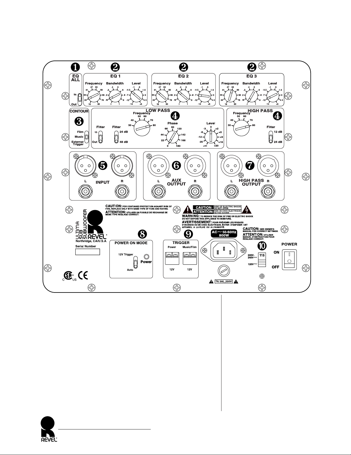
Figure 4. The REVEL
ULTIMA SUB 30’s rear panel
layout shows locations of controls,
as well as audio
and power connectors.
REAR PANEL LAYOUT
❶
EQ ALL: Use this control to bypass all three parametric equalizers
for an audible demonstration of the equalization effect. It can
also prove valuable during the equalization process. For example,
to hear the effect of only one or two of the equalizers, set the
level controls of the remaining equalizer(s) at the “12 o’clock”
position.
❷
EQ 1~ EQ 3: The three parametric equalizers include variable
controls for
Frequency, Bandwidth, and Level. Use these controls
to modify the frequency response at three points, adjustable
from 18 to 80 Hz, across a bandwidth from 0.1 to 1.0 octaves,
with level boost up to 6 dB or level cut to -14 dB.
REVEL ULTIMA SUB 30
Owner’s Manual
10
3O
Page 11

❸
CONTOUR: This control provides access to two different overall
system responses:
Music or Film. Selecting Music does not alter
the subwoofer's response. Selecting
Film provides a tailored
boost at the lowest frequencies that many find desirable for film
sound reproduction. The response contour can be selected
either manually by changing the switch position to
Music or
Film, or automatically by selecting External Trigger to accept a
trigger voltage from an external device, such as a multi-channel
controller, applied to the
TRIGGER Music/Film input terminals.
❹
LOW PASS/HIGH PASS: The LOW PASS filter has In/Out and
24/48 dB slope switches, and variable controls for Frequency,
Phase, and Level. The HIGH PASS filter is always on and has a
variable
Frequency control and 12/24 dB slope switch. Use the
filter controls to precisely set a two-way crossover point from 30
to 80 Hz, with symmetrical 24 dB slopes or asymmetrical 24/12
or 48/12 dB slopes, and low-pass phase shift from 0 to 180
degrees. Use the
LOW PASS Level control to set the subwoofer
system’s output level. When using a multi-channel controller,
the
LOW PASS Level control is normally set to the “0” position.
❺
INPUT: Use stereo XLR (balanced) connectors or RCA (unbal-
anced) jacks to connect from preamplifier outputs, or front
outputs of a multi-channel decoder. Both inputs are 0 dBv
(nominal)/+20 dBv (maximum). The XLR input is pin 2 high.
❻
AUX OUTPUT: Use stereo XLR (balanced) connectors or RCA
(unbalanced) jacks to loop input audio signals to additional
REVEL ULTIMA SUB 30 subwoofers (if present). Both outputs are 0 dBv (nominal)/+20 dBv (maximum). The XLR output is pin 2 high.
❼
HIGH PASS OUTPUT: Use stereo XLR (balanced) connectors or
RCA (unbalanced) jacks for (high-pass) connection to the main
amplifier’s left input. Both outputs are 0 dBv (nominal)/
+20 dBv (maximum). The XLR output is pin 2 high.
❽
POWER ON MODE: Select Auto to turn on automatic power
when the
POWER switch is set to ON. Internal sense circuits will
continually detect the presence of audio signals and fully turn
on the power supply when needed. After some time, when
audio is no longer present, the same circuits will instruct the
power supply to enter the standby mode to conserve energy.
Or select
12V Trigger to turn on/off power via a remote 12 Vdc
supply. A 12-volt trigger voltage is available from some multichannel audio/video controllers, as well as from integrated
remote control systems.
Continued on the next page...
REVEL ULTIMA SUB 30
Owner’s Manual
11
Page 12

REAR PANEL LAYOUT (Continued)
❾
TRIGGER Power and Music/Film: When POWER ON MODE is set
to
12V Trigger, applying a steady 12 Vdc voltage to the TRIGGER
Power
terminals will turn on the REVEL ULTIMA SUB 30.
When
CONTOUR is set to External Trigger, applying a steady
12 Vdc voltage to the
TRIGGER Music/Film terminals will auto-
matically select the
Film contour response. A 12-volt trigger
voltage is available from some multi-channel audio/video controllers, as well as from integrated remote control systems.
➓
POWER ON/OFF Switch, AC Voltage Selector, and Fused Power
Connector for (enclosed) Detachable IEC Power Cord:
If needed, replace the fuse with same type, as follows:
• For 115 Vac @ 60 Hz, use a T6.3AL, 250V slow-blow fuse.
• For 230 Vac @ 50 Hz, use a T6.3AL, 250V slow-blow fuse.
The ac voltage selector sets the subwoofer system for 115 or 230 Vac
operation.Verify the switch setting matches the ac line voltage where
the unit will be operated.
RISK OF ELECTRICAL SHOCK! Only use a qualified
technician to change the ac voltage setting. Make sure the subwoofer
system is turned off and unplugged from the
ac line prior to changing the switch.
CONNECTIONS
Audio interconnection to your main amplifier or home theater
controller can be any combination of unbalanced or balanced
terminations, with full balanced connections offering the best
noise suppression.
Please read the Applications section (starting on the next page)
before proceeding with the actual connections. For clarity, power
connections are not shown. Also, be sure to observe the following:
•Turn off all audio system power before making any connections.
•Read the owner’s manuals that were included with your audio
components to confirm their connection procedures.
REVEL ULTIMA SUB 30
Owner’s Manual
12
IMPORTANT
WARNING
Page 13

APPLICA TIONS
The REVEL ULTIMA SUB 30 powered subwoofer system is very
flexible and can be configured for use in various applications with
associated external components.
As an aid, use the chart below to quickly locate an application with
configuration characteristics that is closest to your desired system.
The most common ones are Figures 5 and 6 (on pages 14 and 15),
where one or more REVEL ULTIMA SUB 30 subwoofers are
connected to a multi-channel controller and use the controller’s
internal crossover.
NOTE: If your multi-channel controller has both SUB and LFE
Outputs, use the SUB Output for the subwoofer system(s) connections.
NOTE: When using the multi-channel controller’s crossover, the crossover
frequency is typically set to 80 Hz for the center, surrounds and back
channels. See “Selecting Crossover Points And Slopes” on page 26.
REVEL ULTIMA SUB 30
Owner’s Manual
13
ULTIMA SUB 30 CONFIGURATION CHARACTERISTICS
APPLICATION
# of Channels Crossover on # of Subs.
High-Pass Out
(Figure #, page #) 2 Multi. Contrl. Sub. 1 Multi. Yes No
Figure 5, page 14 ✔✔ ✔ ✔
Figure 6, page 15 ✔✔ ✔ ✔
Figure 7, page 16 ✔✔✔✔
Figure 8, page 17 ✔✔ ✔ ✔
Figure 9, page 18 ✔✔✔✔
Figure 10, page 19 ✔✔✔✔
Figure 11, page 20 ✔✔✔✔
Figure 12, page 21 ✔✔✔✔
Page 14

Figure 5. How to connect
the REVEL ULTIMA
SUB 30 to a home
theater multi-channel controller
using the controller’s crossover.
APPLICATIONS (Continued)
MUL TI-CHANNEL CONTROLLER WITH CROSSOVER
AND A REVEL UL TIMA SUB 30
In this application, the REVEL ULTIMA SUB 30’s internal filter
is bypassed and the multi-channel controller’s crossover is used
instead, as shown in Figure 5.
REVEL ULTIMA SUB 30
Owner’s Manual
14
ULTIMA SUB 30 Rear Panel (split view)
*To SUB/LFE Output
(if using optional Y-adapter)
Use L or R Input and Increase
Low Pass Level to +6 dB;
Multi-Channel Controller (Decoder)
(rear)
Left Output
FRONT/MAIN
Right Output
Left Output
REAR
Right Output
Left Output
SURROUND/SIDE
Right Output
CENTER Output
SUB/LFE Output
NOTE: Set Controller to
SUB “On” and all speakers
to cross over (typically)
at 80 Hz.
Main Amplifier
(rear)
To Main Speakers
Left Input
Left Right
Right Input
or or
or
or
or
Page 15

Figure 6. How to connect
multiple REVEL ULTIMA SUB
30 subwoofers to a home
theater multi-channel controller
using the controller’s crossover.
MUL TI-CHANNEL CONTROLLER WITH CROSSOVER
AND MUL TIPLE REVEL ULTIMA SUB 30 SUBWOOFERS
Multiple REVEL ULTIMA SUB 30 subwoofers can be connected
in a “daisy-chain” with a multi-channel controller (using its
crossover) and power amplifier, as shown in Figure 6.
REVEL ULTIMA SUB 30
Owner’s Manual
15
#1 ULTIMA SUB 30 Rear Panel
(split view)
#2 ULTIMA SUB 30 Rear Panel
(split view)
Use L or R Input and Increase
Low Pass Level to +6 dB;
*Or Use Optional
Y-adapter, If Desired.
Main Amplifier
(rear)
To Main Speakers
Left Input
Left Right
Right Input
Multi-Channel Controller (Decoder)
(rear)
Left Output
FRONT/MAIN
Right Output
Left Output
REAR
Right Output
Left Output
SURROUND/SIDE
Right Output
CENTER Output
SUB/LFE Output
NOTE: Set Controller to SUB
“On” and all speakers to cross
over (typically) at 80 Hz.
or or
or
RCA cables
to #2 sub.
INPUT
or
(Optional)
RCA cables
to #3 sub.
INPUT
(Optional)
XLR cables
to #3 sub.
INPUT
or
RCA cables
to #1 sub.
AUX OUTPUT
or
or
or
*To SUB/LFE Output
(if using optional Y-adapter)
*To SUB/LFE Output
(if using optional Y-adapter)
Page 16

Figure 7. How to connect
the REVEL ULTIMA
SUB 30 to a home theater
multi-channel controller using
the subwoofer’s internal
crossover.
APPLICATIONS (Continued)
MUL TI-CHANNEL CONTROLLER AND A REVEL ULTIMA
SUB 30 WITH CROSSOVER
In this application, the REVEL ULTIMA SUB 30’s
internal crossover is used to interconnect a home theater
multi-channel controller, as shown in Figure 7.
REVEL ULTIMA SUB 30
Owner’s Manual
16
ULTIMA SUB 30 Rear Panel (split view)
Multi-Channel Controller (Decoder)
(rear)
Left Output
FRONT/MAIN
Right Output
Left Output
REAR
Right Output
Left Output
SURROUND/SIDE
Right Output
CENTER Output
SUB/LFE Output
NOTE: Set Controller outputs to
full-range L/R Front and no SUB.
If applicable, set all other channels
to pass 80 Hz (typically) and above.
Below 80 Hz (typically), signals will
route to the ULTIMA SUB 30.
Main Amplifier
(rear)
To Main Speakers
Left Input
Left Right
Right Input
or
or
or or
Page 17

Figure 8. How to connect two
REVEL ULTIMA SUB 30
subwoofers to a Surround-Sound
Processor using the processor’s
internal crossover for stereo bass.
SURROUND-SOUND PROCESSOR WITH CROSSOVER
AND REVEL ULTIMA SUB 30 SPEAKERS IN STEREO
Two REVEL ULTIMA SUB 30 speakers can be used for stereo
bass with a surround-sound processor after it is configured for left
and right subwoofer outputs, as shown in Figure 8.
REVEL ULTIMA SUB 30
Owner’s Manual
17
Right ULTIMA SUB 30 Rear Panel
(split view)
Left ULTIMA SUB 30 Rear Panel
(split view)
Surround-Sound Processor
(rear)
NOTE: On some Surround-Sound Processors,
the SUBWOOFER Outputs may be labeled AUX.
Set the crossover to route low-frequency signals
(typically below 80 Hz) to the SUBWOOFER or
AUX outputs.
Left Output
FRONT/MAIN
Right Output
Left Output
REAR
Right Output
Left Output
SUBWOOFER
Right Output
Left Output
SURROUND/SIDE
Right Output
CENTER Output
SUB/LFE Output
or
or
Page 18

Figure 9. How to connect
two REVEL ULTIMA SUB 30
subwoofers to a home theater
multi-channel controller using
the subwoofers’ internal
crossovers.
APPLICATIONS (Continued)
MUL TI-CHANNEL CONTROLLER
AND REVEL ULTIMA
SUB 30 SUBWOOFERS WITH CROSSOVERS IN
STEREO
Using internal crossovers, two REVEL ULTIMA SUB 30 subwoofers
can also be set up for stereo bass with a multi-channel controller, as
shown in Figure 9.
REVEL ULTIMA SUB 30
Owner’s Manual
18
Right ULTIMA SUB 30 Rear Panel
(split view)
Left ULTIMA SUB 30 Rear Panel
(split view)
Main Amplifier
(rear)
To Main Speakers
Left Input
Left Right
Right Input
Multi-Channel Controller (Decoder)
(rear)
Left Output
FRONT/MAIN
Right Output
Left Output
REAR
Right Output
Left Output
SURROUND/SIDE
Right Output
CENTER Output
SUB/LFE Output
NOTE: Set Controller outputs to
full-range L/R Front and no SUB.
If applicable, set all other channels
to pass 80 Hz (typically) and above.
Below 80 Hz (typically), signals will
route to the ULTIMA SUB 30 subwoofers.
or or
or
or
(Optional)
To SUB/LFE Output
(use Y-adapter)
(Optional)
To SUB/LFE Output
(use Y-adapter)
Page 19

Figure 10. How to connect
the REVEL ULTIMA SUB 30
(with its internal high-pass
crossover) between a stereo
preamplifier and main power
amplifier .
STEREO POWER AMPLIFIER AND A REVEL SUB 30
WITH CROSSOVER
The most common two-channel application is interconnecting the
REVEL ULTIMA SUB 30 between a stereo preamplifier and the
main power amplifier, as shown in Figure 10.
REVEL ULTIMA SUB 30
Owner’s Manual
19
ULTIMA SUB 30 Rear Panel
(split view)
Preamplifier
(rear)
Left Output Right Output
Main Amplifier
(rear)
To Main Speakers
Left Input
Left Right
Right Input
or or
oror
Page 20

Figure 11. How to connect
multiple REVEL ULTIMA SUB
30 subwoofers to a home
theater multi-channel controller
using the subwoofers’ crossovers.
APPLICATIONS (Continued)
MUL TI-CHANNEL CONTROLLER
AND MULTIPLE REVEL
ULTIMA SUB 30 SUBWOOFERS WITH CROSSOVERS
Multiple REVEL ULTIMA SUB 30 subwoofers (using their internal crossovers) can be connected in a “daisy-chain” with a multichannel controller and power amplifier, as shown in Figure 11.
REVEL ULTIMA SUB 30
Owner’s Manual
20
#1 ULTIMA SUB 30 Rear Panel
(split view)
#2 ULTIMA SUB 30 Rear Panel
(split view)
Multi-Channel Controller (Decoder)
(rear)
Left Output
FRONT/MAIN
Right Output
Left Output
REAR
Right Output
Left Output
SURROUND/SIDE
Right Output
CENTER Output
SUB/LFE Output
NOTE: Set Controller outputs to
full-range L/R Front and no SUB.
If applicable, set all other channels
to pass 80 Hz (typically) and above.
Below 80 Hz (typically), signals will
route to the ULTIMA SUB 30.
Main Amplifier
(rear)
To Main Speakers
Left Input
Left Right
Right Input
or
or
or or
or
(Optional)
RCA cables
to #3 sub.
INPUT
or
RCA cables
to #2 sub.
INPUT
(Optional)
XLR cables
to #3 sub.
INPUT
XLR cables
to #2 sub.
INPUT
On all subs.
XLR cables
from #1 sub.
AUX OUTPUT
or
RCA cables
from #1 sub.
AUX OUTPUT
Page 21

Figure 12. How to connect
the REVEL ULTIMA SUB 30
(without its internal high-pass
crossover) between a stereo pre-
amplifier and main power
amplifier .
STEREO POWER AMPLIFIER AND A REVEL ULTIMA
SUB 30 WITHOUT HIGH-PASS CROSSOVER
Revel strongly recommends using both a low-pass and high-pass
crossover with any “main” left and right loudspeakers of any size.
The use of a high-pass crossover greatly reduces distortion, increases
dynamic range, and optimizes the transition from the REVEL
ULTIMA SUB 30 to the main loudspeakers.
If you plan to use the REVEL ULTIMA SUB 30 without a highpass crossover (see Figure 12), contact your Revel dealer for help in
setting the crossover controls so the main speakers and the REVEL
ULTIMA SUB 30 subwoofer(s) will produce an optimum combined response.
REVEL ULTIMA SUB 30
Owner’s Manual
21
NOTE: Use Y-adapters or Subwoofer
Outputs on Preamplifier (if available)
to drive the ULTIMA SUB 30.
Preamplifier
(rear)
Left Output Right Output
Main Amplifier
(rear)
To Main Speakers
Left Input
Left Right
Right Input
ULTIMA SUB 30 Rear Panel
(split view)
or or
Y-adapter
Y-adapter
Y-adapter
Y-adapter
NOTE: Adjust for optimum
blend with front speakers.
or
Page 22

SYSTEM OPTIMIZATION
The REVEL ULTIMA SUB 30 includes built-in 3-band parametric equalizers for use with sound measurement equipment having
at least one-tenth-octave resolution at 20 Hz. Do not use crude
measurement devices, such as most real-time or one-thir d-octave
analyzers, to measure low-frequency performance in a listening
room. Room boundaries often cause modes or standing waves with
very narrow-band peaks and dips that are beyond this equipment’s
measurement-resolution capability. Adjusting the parametric equalizers based on this data can result in very misleading results and
degraded sound quality.
PLACEMENT OVERVIEW
Below 300 Hz, the relationship of loudspeaker placement and
listener location has a profound impact on the way sound is reproduced. All rooms have “standing waves,” where certain frequencies
are emphasized or diminished. Their complex patterns, along with
the effect of surfaces near the loudspeakers or listeners, can combine
to introduce tremendous sound coloration at low frequencies.
Revel’s unique parametric equalization system offers a powerful
tool to help compensate for these effects. However, no electronic
system alone can fully compensate for the dramatic effects of room
acoustics. Every room will have locations where “nulls” at specific
frequencies occur. These cancellations of the sound are like “black
holes,” which no amount of equalization can fill. The best results
are always achieved through careful placement of both the loudspeakers and the listening position. Optimum placement can be
determined through the use of computer modeling programs, or
by trial-and-error measurements. If at all possible, find the best
loudspeaker and listener locations before proceeding with adjustments of the Revel parametric equalizers.
To help determine good locations for the subwoofer(s) and the
listener(s), we recommend making high-resolution in-room response
measurements by using either the REVEL LOW FREQUENCY
OPTIMIZER (LFO) software, or other high resolution (
1
⁄10-octave
or better) measurement systems. The latest Revel LFO software can
be downloaded at www.revelspeakers.com. This system provides the high-resolution data needed for useful low-frequency measurements. Traditional realtime analyzers (RTAs) or
1
⁄3-octave mea
surements have inadequate resolution, often resulting in misleading
data and degraded sound quality.
REVEL ULTIMA SUB 30
Owner’s Manual
22
IMPORTANT
Page 23

Figure 13. Typical corner
placement of a REVEL
ULTIMA SUB 30 in an
average room.
NOTE: Another placement
choice is mid-way along one of
the walls with the front wall
being the most convenient (see
alternate placement).
Simply use the Revel LFO test signals disc, and the LOW
FREQUENCY OPTIMIZER will plot the results of the measurement at each speaker or listener (microphone) location.
The REVEL LOW FREQUENCY OPTIMIZER provides a
convenient way to save each set of measurements and to make
notes so that the effect of various locations can be compared.
Other sound measurement systems may also be used to help
determine speaker and listener locations, as long as the selected
equipment provides at least one-tenth -octave resolution at 20 Hz.
GENERAL PLACEMENT GUIDELINES
• As a general rule, placing a subwoofer in the corner of a room
(see Figure 13 below) will result in the maximum number of
“peaks” and minimum number of “dips” in the response. Most
dips cannot be equalized, but they can be minimized through
optimum placement of subwoofer(s) and the listening position.
The resulting peaks can be corrected through the use of our
powerful built-in parametric equalization.
•Due to the nature of room acoustics, experiment with different
listening location(s), as well as loudspeaker locations, to obtain
the best sound at low frequencies.
Continued on the next page...
REVEL ULTIMA SUB 30
Owner’s Manual
23
Listening Position
(e.g., on couch)
SUB 30
Subwoofer
SUB 30
Subwoofer
L Speaker R Speaker
(alternate placement)
(typical placement)
Page 24

Figure 14. Preferred placement
of two REVEL ULTIMA SUB
30 subwoofers in diagonallyopposite corners of a room.
SYSTEM OPTIMIZATION
GENERAL PLACEMENT GUIDELINES (Continued)
•For best results, place the REVEL ULTIMA SUB 30 near solid
walls to reinforce bass response, and avoid windows which can
rattle and transmit sound to the outside world.
•If you plan to use two REVEL ULTIMA SUB 30 subwoofers
and you cannot make high-resolution measurements, tr y placing
the subwoofer systems at diagonally-opposite corners or at the
mid-points of opposite walls, as shown in Figure 14. Moreover,
use a modeling program or trial-and-error measurements to
further determine the best locations that will minimize response
dips due to standing wave cancellation.
• The smoothest low frequency response with the most consistent
sound throughout the listening area can be achieved through
the use of four properly-placed REVEL ULTIMA SUB 30
subwoofers (see Figure 14 above). The flattest response is usually obtained by placing one pair at the mid-way point of the
opposite front and back walls, and a second pair at the mid-way
points of the side walls. Use in-room measurements to fine-tune
the locations to account for variations in construction among
the room walls.
REVEL ULTIMA SUB 30
Owner’s Manual
24
Listening Position
(e.g., on couch)
SUB 30
Subwoofer
SUB 30
Subwoofer
Subwoofer
Subwoofer Subwoofer
SUB 30
SUB 30
L Speaker
(alternate placement)(alternate placement)
SUB 30
Subwoofer
(alternate placement)(alternate placement)
(alternate
placement)
(alternate
placement)
R Speaker
Subwoofer
Subwoofer
SUB 30
SUB 30
SUB 30
Page 25

• The placement of the other system loudspeakers in the listening
room system will also affect the way sound (below 300 Hz) is
reproduced. Just as is the case with subwoofers, use a modeling
program or trial-and-error measurements to determine the
best locations.
•Since listening and loudspeaker locations are equally important,
the trial-and-error process can be time-consuming. However,
the sonic rewards are great. Remember that peaks (below the
subwoofer crossover frequency) can be eliminated by the proper
adjustment of the REVEL ULTIMA SUB 30’s EQ controls,
but most dips cannot be corrected. Therefore, the most important objective is to find locations that result in the minimum
number and severity of dips.
SOUND MEASUREMENT GUIDELINES
•If you are using a modeling program, begin by placing the
microphone at ear height at the recommended listening position, with the subwoofer placed at the calculated position.
Choose a location that has been used for listening in the past.
Otherwise, select a location that is most desirable for aesthetic
or other considerations. If the locations are to be determined
by trial-and-error, begin with one REVEL ULTIMA SUB 30
in a front corner of the room (nearest the main loudspeakers).
• As a starting point, avoid selecting listening locations that are
near the middle, or at one-quarter or three-quarters of the
room’s length (front-to-back), where large cancellation dips
often occur.
•Use care when locating the listening position away from the
center of the room’s width, as imaging characteristics may be
degraded. Off-center locations will usually work only when the
side walls are acoustically treated with absorbent materials, or
if the room is exceptionally wide.
•For best results, use a camera tripod with a Sound Level Meter,
or a microphone stand for the microphone.
REVEL ULTIMA SUB 30
Owner’s Manual
25
Page 26

REVEL ULTIMA SUB 30
Owner’s Manual
26
SYSTEM OPTIMIZATION (Cont’d)
SELECTING CROSSOVER POINTS AND SLOPES
The ideal way to select crossover frequencies is by making in-room
acoustic measurements. The proper choice of crossover frequencies
can dramatically improve low-frequency smoothness and blending
of the main speakers with the subwoofer(s).
Begin by measuring the left and right speakers (together), without
any crossover. Then measure the center channel without a crossover
and the subwoofer(s) either without a crossover, or with the
multi-channel controller’s subwoofer crossover set to the highest
available frequency.
Use the results of the actual in-room measurements to examine the
responses of the left, center, and right speakers, and subwoofer(s)
below around 120 Hz. For example, if the subwoofer(s) exhibit a
large “dip” in response at 75 Hz, and the left and right speakers
have better response at 75 Hz, it would be wise to set the crossover
to 70 or even 60 Hz. In general, the crossover point should be set
as high as possible to optimize the system’s dynamic range and to
minimize distortion.
Consult your Revel dealer for additional information on choosing
crossover frequencies and slopes.
Page 27

CABINET CARE
The REVEL ULTIMA SUB 30 cabinet has a paint finish and does
not require any routine maintenance. Use a soft cloth, dampened
with water only, to remove any fingerprints or to wipe off dust.
Clean the grille by gentle vacuuming.
For wood side panels, occasionally use a household furniture polish
to maintain the beauty of the hardwood veneers.
For aluminum side panels, use a soft cloth, dampened with soapy
water only. Wipe in the direction of the grain only.
TROUBLESHOOTING
If the REVEL ULTIMA SUB 30 sounds distorted, stops playing,
or otherwise seems to be malfunctioning, first determine whether
the problem is in the subwoofer system, the wiring, and/or other
audio components. If the problem also affects the main speakers,
the cause is most likely in your electronics. If it is only noticed in
the subwoofer system, make sure that all connecting cables are correct and in proper working condition. Make sure the subwoofer system is plugged in and turned on.
If everything seems to be in good working order and the subwoofer
system still malfunctions, contact your Revel dealer for assistance
(see Obtaining Service on the next page).
Do not attempt to repair the REVEL ULTIMA SUB 30
subwoofer system yourself.
REVEL ULTIMA SUB 30
Owner’s Manual
27
IMPORTANT
Page 28

OBTAINING SERVICE
We take great pride in our dealers. Experience, dedication, and
integrity make these professionals ideally suited to assist with our
customers’ service needs.
If your Revel component requires service, please contact your dealer.
Your dealer will then decide whether the problem can be remedied
locally, whether to contact Harman Specialty Group for further
service information or parts, or to obtain a Return Authorization.
The Technical Services Department at Harman Specialty Group
works closely with your dealer to solve your service needs expediently.
Return authorization must be obtained from the Technical Services
Department at Harman Specialty Group BEFORE a unit is
shipped for service.
It is extremely important that information about a problem be
explicit and complete. A specific, comprehensive description of the
problem helps your dealer and the Technical Services Department at
Harman Specialty Group locate and repair the difficulty as quickly
as possible. A copy of the original bill of sale will serve to verify
warranty status. Please include it with the component when it is
brought in for warranty service.
All returned units must be properly packaged in their original packing material, and the proper return authorization numbers must be
marked on the outer carton for identification. If the packaging to
protect the unit is in our opinion or that of our dealer inadequate
to protect the unit, we reserve the right to repackage it for return
shipment at the owner’s expense. Neither Harman Specialty Group
nor your dealer can be responsible for shipping damage due to
improper (i.e., non-original) packaging.
Your dealer can order a new set of shipping materials for you if you
need to ship your component and no longer have the original materials, or if they are in poor condition. There will be a charge for this
service. We strongly recommend saving all packing materials in case
you need to ship your unit some day. For more information, see
your Revel dealer, or contact:
Harman Specialty Group
3 Oak Park
Bedford, MA, 01730 - 1413, USA
Tel.: 781 - 280 - 0300
FAX: 781 - 280 - 0490
www.harmanspecialtygroup.com
REVEL ULTIMA SUB 30
Owner’s Manual
28
IMPORTANT
WARNING
Page 29

Figure 15. Overall dimensions
for the REVEL ULTIMA SUB
30 subwoofer system.
SPECIFICA TIONS
Revel utilizes proprietary measurement methods in the design and
specification of our loudspeakers. Our research has developed a series
of tests that represent a great leap forward in making measurements
that dramatically contribute to our goal of accurately reproducing
music or film. REVEL ULTIMA SUB 30 specifications for the
subwoofer and amplifier are as follows:
SUBWOOFER
Low Frequency Extension: -3 dB @ 18 Hz (up to full-rated power)
Frequency Response: 20 Hz to fc±0.5 dB, - 3 dB @ 18 Hz
True Linear Volume
Displacement: 275 in
3
Weight (with amplifier): 145 lb (66.8 kg) net, including carton.
Overall Dimensions: 231⁄4"H x 20" W x 233⁄4"D
591 mm H x 508 mm W x 603 mmD
(with grille and feet; see Figure 15 below)
AMPLIFIER
Output Power: At least 1,000 W
rms
, 1,400 W
peak
EQ ALL Control: Engages all three parametric equalizers,
or bypasses them
CONTOUR Control: Selects Film, Music, or External Trigger EQ mode
Equalization –
Type: Three independent parametric equalizers
Frequency: Continuously variable from 18 to 80 Hz
Continued on the next page...
REVEL ULTIMA SUB 30
Owner’s Manual
29
20"
(508 mm)
23-1⁄4"
(591 mm)
17-7⁄8"
(454 mm)
20-7⁄8"
(530 mm)
20-1⁄2"
(521 mm)
23-3⁄4"
(603 mm)
2-3⁄16"
(56 mm)
Page 30

SPECIFICA TIONS
AMPLIFIER (Continued)
Equalization (Continued) –
Bandwidth: Continuously variable from 0.1 to 1.0 Octave
Level: Continuously variable from -14 to+6 dB
Low-Pass Filter –
Type: Low pass with ON/OFF switch
Slope: Selectable 24 or 48 dB per octave
Frequency: Selectable at 30, 40, 50, 60, 70, or 80 Hz
Phase: Continuously variable from 0 to 180°
Level: Continuously variable
High-Pass Filter –
Type: High pass, always on
Slope: Selectable 12 or 24 dB per octave
Frequencies: Selectable at 30, 40, 50, 60, 70, or 80 Hz
Audio Inputs: Left and right balanced (XLR) and unbalanced
(RCA) line level
Audio Outputs: Left and right balanced (XLR) and unbalanced
(RCA) high-pass line level to main amplifier
Left and right balanced (XLR) and unbalanced
(RCA) line level to auxiliary components
Trigger Inputs: Power connectors for triggering system power on
when 12 Vdcis applied to the terminals
Music/Film connectors for triggering CONTOUR
to Film EQ mode when 12 Vdcis applied to
the terminals
POWER ON MODE Switch: Selects either AUTO or 12 Vdctrigger-controlled
operation
POWER ON/OFF Switch: Selects either fully-off, or the operation mode
selected by the POWER ON MODE Switch
Power: 120 Vac@ 60 Hz, 720 W
rms
with T6.3AL SLO-BLO or Time-Lag fuse
240 Vac@ 50 Hz, 720 W
rms
with T6.3AL SLO-BLO or Time-Lag fuse
Switch: 12 V Trigger or AUTO
Revel, a division of Harman Specialty Group, constantly strives to update and improve existing products, as well as
create new ones. Therefore, the specifications and construction details in this and related Revel publications are
subject to change without notice. Kapton and Kevlar are registered trademarks of the E.I. du Pont de Nemours
Company. Revel Ultima is a trademark and Revel is a registered trademark of Harman International Industries, Inc.
© Harman International, 2003.
REVEL ULTIMA SUB 30
Owner’s Manual
30
Page 31

NOTES
REVEL ULTIMA SUB 30
Owner’s Manual
31
Page 32

P/N 337740-001
3 Oak Park, Bedford, MA 01730-1413 USA | Tel: 781-280-0300 | Fax: 781-280-0490 | www.harmanspecialtygroup.com
 Loading...