

Revel Sub15 Owner's Manual

Revel®Ultima™SUB-15/LE-1
WARNING: TO REDUCE THE RISK OF FIRE OR ELECTRIC SHOCK,
DO NOT EXPOSE THIS PRODUCT TO RAIN OR MOISTURE.
ULTIMA SUB-15/LE-1
Owner’s Manual
2
CAUTION
RISK OF ELECTRIC SHOCK
DO NOT OPEN
CAUTION: TO REDUCE THE RISK OF ELECTRIC SHOCK,
DO NOT REMOVE COVER (OR BACK).
NO USER-SERVICEABLE PARTS INSIDE.
REFER SERVICING TO QUALIFIED SERVICE PERSONNEL.
The lightning flash with arrowhead symbol, within an equilateral triangle, is intended to alert the user to the presence of
uninsulated “dangerous voltage” within the product’s enclosure
that may be of sufficient magnitude to constitute a risk of electric shock to persons.
The exclamation point within an equilateral triangle is
intended to alert the user to the presence of important operating and maintenance (servicing) instructions in the literature
accompanying the product.

IMPORTANT SAFETY INSTRUCTIONS
Please read all instructions carefully and completely before
operating your REVEL
®
ULTIMA™ SUB-15/LE-1 powered
subwoofer system.
1. Always disconnect ac power before connecting or disconnecting any cables, or when cleaning any component.
2. This product uses a three-conductor power cord, which
includes an earth-ground connection. To prevent shock hazard,
always connect it directly to a grounded outlet.
3. Never use any ac extension cord with this product.
4. Never use flammable or combustible chemicals for cleaning
audio components.
5. Never operate this product with any covers removed.
6. Never wet the inside of this product with any liquid.
7. Never pour or spill liquids directly onto this unit.
8. Never block air flow through ventilation slots or heatsinks.
9. Never bypass any fuse.
10. Never replace any fuse with a value or type other than specified.
11. Never attempt to repair this product yourself. If a problem
occurs, contact your Revel retailer.
12. Never expose this unit to extremely high or low temperatures.
13. Never operate this product in an explosive atmosphere.
14. Always keep electrical equipment out of the reach of children.
ULTIMA SUB-15/LE-1
Owner’s Manual
3

TABLE OF CONTENTS
INTRODUCTION .........................................................5
ABOUT THE MANUAL AND WARRANTY...................................................5
DESCRIPTION............................................................6
SUB-15 ..............................................................................................6
LE-1...................................................................................................6
UNPACKING..............................................................7
UNPACKING THE SUB-15.....................................................................7
UNPACKING THE LE-1 .........................................................................8
INSPECTING THE SUB-15/LE-1.............................................................8
INSTALLING SPIKE FEET ONTO THE SUB-15 ..........................................8
PLACEMENT............................................................10
SUB-15 PLACEMENT .........................................................................10
LE-1 PLACEMENT..............................................................................12
LE-1 LAYOUTS.........................................................13
FRONT PANEL LAYOUT .......................................................................13
REAR PANEL LAYOUT .........................................................................14
REMOTE CONTROL LAYOUT................................................................16
CONNECTIONS........................................................17
STEREO POWER AMPLIFIER ...............................................................19
MULTI-CHANNEL CONTROLLER
USING THE LE-1’S CROSSOVER..........................................................20
MULTI-CHANNEL CONTROLLER
USING THE CONTROLLER’S CROSSOVER .............................................21
WITHOUT HIGH-PASS CROSSOVER .....................................................22
MULTIPLE OPERATION .......................................................................23
STEREO BASS ...................................................................................24
SYSTEM OPTIMIZATION ............................................25
BASIC SYSTEM OPTIMIZATION.............................................................25
OPTIMIZING PERFORMANCE WITH A TEST CD .....................................26
ROOM GAIN COMPENSATION .............................................................27
AUTOMATIC MUSIC SENSOR .....................................28
TRIGGERED POWER CONTROL.................................29
A NOTE ABOUT POWER MANAGEMENT ...............................................29
LOW FREQUENCY GAIN SWITCH...............................30
LOW FREQUENCY LIMITER SETTING..........................31
CROSSOVER SLOPE AND FREQUENCY SELECTION .....32
CABINET CARE ........................................................33
AMPLIFIER CARE .....................................................33
TROUBLESHOOTING ................................................33
OBTAINING SERVICE ................................................35
SPECIFICATIONS......................................................36
SUB-15 ............................................................................................36
LE-1.................................................................................................37
ULTIMA SUB-15/LE-1
Owner’s Manual
4
INTRODUCTION
The REVEL®ULTIMA™ SUB-15/LE-1 powered subwoofer system
combines an exceptional 15" subwoofer with a separate 700-watt (rms)
low-frequency electronics section for greater installation flexibility. The
ULTIMA SUB-15’s graceful form and deceptively small size provide a
surprisingly prodigious output and unprecedented tonal accuracy, even
in the deepest octaves. The ULTIMA LE-1’s impressive features and
interchangeable filter module let you customize and adapt the powered
subwoofer system in a wide variety of applications.
The ULTIMA SUB-15/LE-1 powered subwoofer system is an ideal
companion for all Revel loudspeakers, as it integrates more precisely
with other manufacturers’ speakers than any other subwoofer.
ABOUT THE MANUAL AND WARRANTY
To begin enjoying your ULTIMA SUB-15/LE-1 powered subwoofer
system, first read and then perform the instructions in this owner’s
manual. Maximum performance is dependent on following all
instructions described here, as well as those found in the owner’s
manuals of associated components in your audio system. Save these
instructions for future reference.
The ULTIMA SUB-15/LE-1 system is covered by a limited warranty,
so save the bill of sale to protect your purchase and aid in any
service-related questions.
ULTIMA SUB-15/LE-1
Owner’s Manual
5
P
o
w
e
r
L
o
w
F
re
q
ue
n
c
y
O
p
ti
o
n
L
e
v
e
l
P
h
a
s
e
Phase
;;;;;;;
;;;;;
;;;
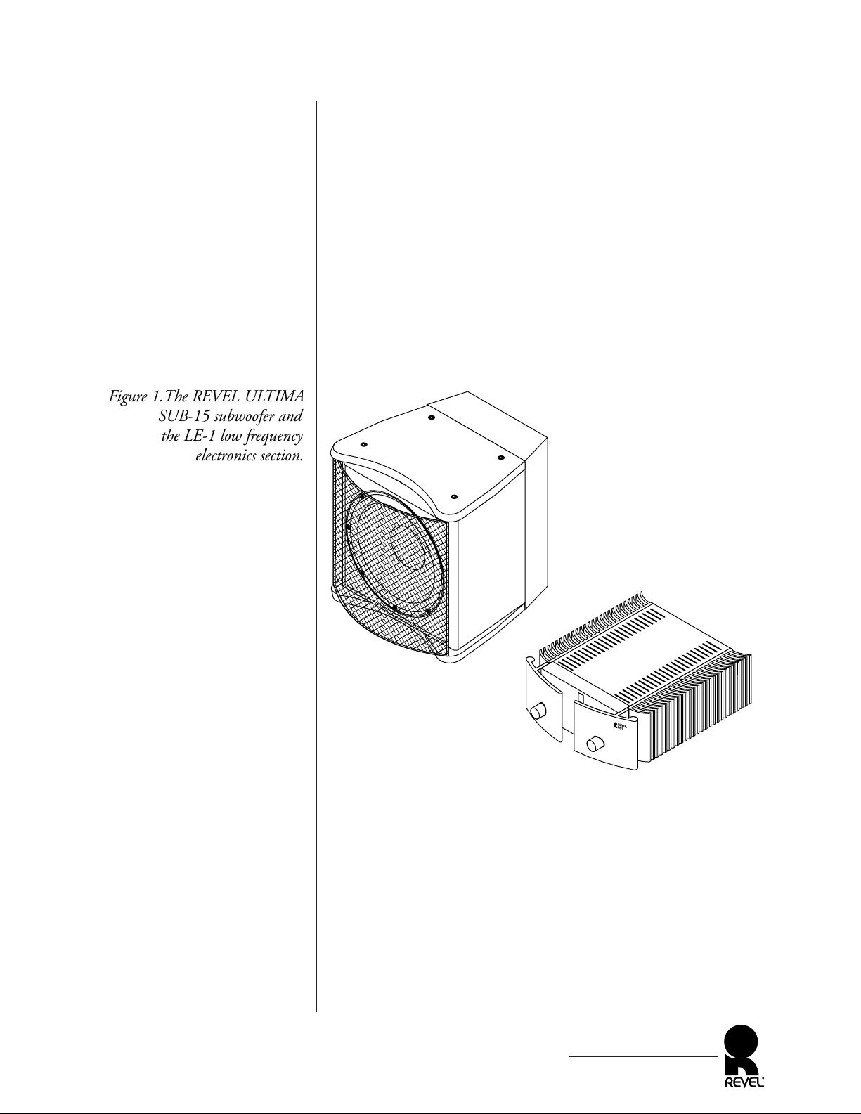
Figure 1.The REVEL ULTIMA
SUB-15 subwoofer and
the LE-1 low frequency
electronics section.

DESCRIPTION
The REVEL ULTIMA SUB-15 features a unique transducer that
combines the brute-force capabilities of sound reinforcement drivers
with the nuances necessary for audiophile sound reproduction.
Combined with the LE-1’s huge power capability, the result is a
new standard of superb bass performance and adaptability for home
entertainment systems.
SUB-15
To ensure uncompressed dynamic range, each ULTIMA SUB-15 is
unique in the following ways:
• Oversized 4-inch diameter voice coil with flat copper wire
offers higher power handling and freedom from compression
for control of low frequencies during high acoustic output.
• Extremely long-throw voice coil is capable of 1.5 inches of
peak-to-peak linear excursion, and 2 inches of maximum
excursion for pure reproduction of deep sustained bass notes.
• Ultra-rigid Kevlar
®
- and Kapoc®-impregnated cellulose pulp
cone body and dome operate as a perfect piston under all
reproduction conditions.
• The heavy wall, cast aluminum frame maintains alignment
between the massive 35-pound magnet structure and the moving elements, while offering excellent rigidity.
The ULTIMA SUB-15 cabinet has been optimally designed and
internally braced with the aid of laser interferometry. Integral top
and bottom panels provide a custom look via available finishes.
LE-1
The ULTIMA LE-1’s amplifier section is rated for a minimum
700 watts (rms) into a single ULTIMA SUB-15, and a minimum
1,200 watts (rms) into two ULTIMA SUB-15s under actual load
conditions. A unique circuit can be switched in to provide compensation for room gain. A remote control provides the listener
with wireless control to set optimum performance while seated in
the listening position. The internal FM-2 electronic crossover
offers truly optimized performance for ideal blending between one
or two ULTIMA SUB-15s and any main loudspeakers.
ULTIMA SUB-15/LE-1
Owner’s Manual
6
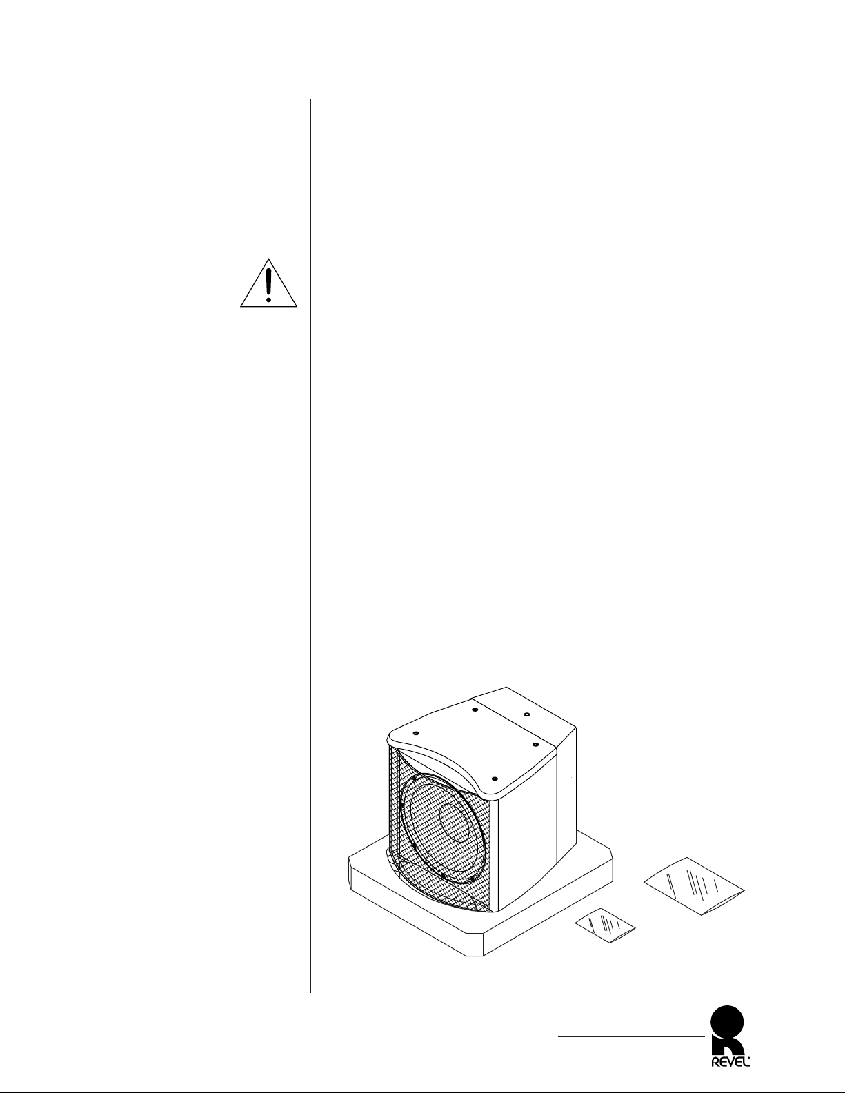
Figure 2.The ULTIMA SUB-15
subwoofer with its inner
packing materials.
UNPACKING
Each ULTIMA SUB-15 and LE-1 are packed in individual cartons
with a combined shipping weight exceeding 198 pounds. To avoid
personal injury and possible product damage, we strongly urge you
to enlist additional help before unpacking either product. Also, be
sure to observe the following precautions and procedures:
• Do not attempt to lift either product from its packing carton alone. To unpack a product properly, at least two strong
people will be needed.
• To avoid injury, use extreme care during unpacking.
• Do not lift a product while bending from the waist.
• Always stand as straight as possible and use leg muscles to
lift a product.
UNPACKING THE SUB-15
1. At the final placement choice (see Placement on page 10), set
the packaged ULTIMA SUB-15 subwoofer on a rug or other
soft material in the up position. Open the top flaps and set
aside the spike foot kit and owner’s manual.
2. With the top flaps folded back, roll the carton over onto its
exposed top pad. Open the bottom flaps and fold them back.
Remove the bottom pad.
3. Lift the carton off the subwoofer and set it aside, being careful
not to damage the contents (see Figure 2 below).
...continued on next page
ULTIMA SUB-15/LE-1
Owner’s Manual
7
WARNING
Top Pad
Warranty Card and
Owner’s Manual
Spike Foot Kit
UNPACKING
UNPACKING THE SUB-15 (Continued)
4. If you plan to add spike feet, perform the instructions in the
last section, Installing Spike Feet Onto The Sub-15.
5. If you don’t use spikes, roll the subwoofer onto its bottom and
remove the top pad. Use caution to avoid scraping the finish or
pulling off the grille.
UNPACKING THE LE-1
1. Set the packaged ULTIMA LE-1 on its top onto a rug or other
soft material.
2. Open the bottom flaps and fold them back. Roll the carton
over onto its exposed bottom pad.
3. Lift the carton off the ULTIMA LE-1 and set it aside, being
careful not to damage the contents.
4. Remove the top and front pads. Grab the sides and lift the
ULTIMA LE-1 up off its bottom pad.
Do not lift the ULTIMA LE-1 using the knobs.
INSPECTING THE SUB-15/LE-1
After unpacking both products, carefully inspect the ULTIMA
SUB-15 and LE-1 for possible damage due to shipping. If you
discover any damage, immediately contact your Revel dealer for
further assistance.
Keep all packing materials for future shipping. In the unlikely
event a product will need repair, Revel will only accept a unit in its
original shipping carton. Using any other packing materials may
result in damage to the product and is not covered by the warranty.
See Obtaining Service on page 35 for additional details.
INSTALLING SPIKE FEET ONTO THE SUB-15
1. Verify the spike foot kit contains three (3) spike feet, three (3)
covers, one (1) trim ring, one (1) wrench, and an adhesive packet.
2. Using the enclosed wrench, remove the two front bolts and
trim rings from the bottom panel, as shown in Figure 3 (on
the next page). Hold onto the trim rings for step 3. Store the
bolts for possible future use.
ULTIMA SUB-15/LE-1
Owner’s Manual
8
IMPORTANT
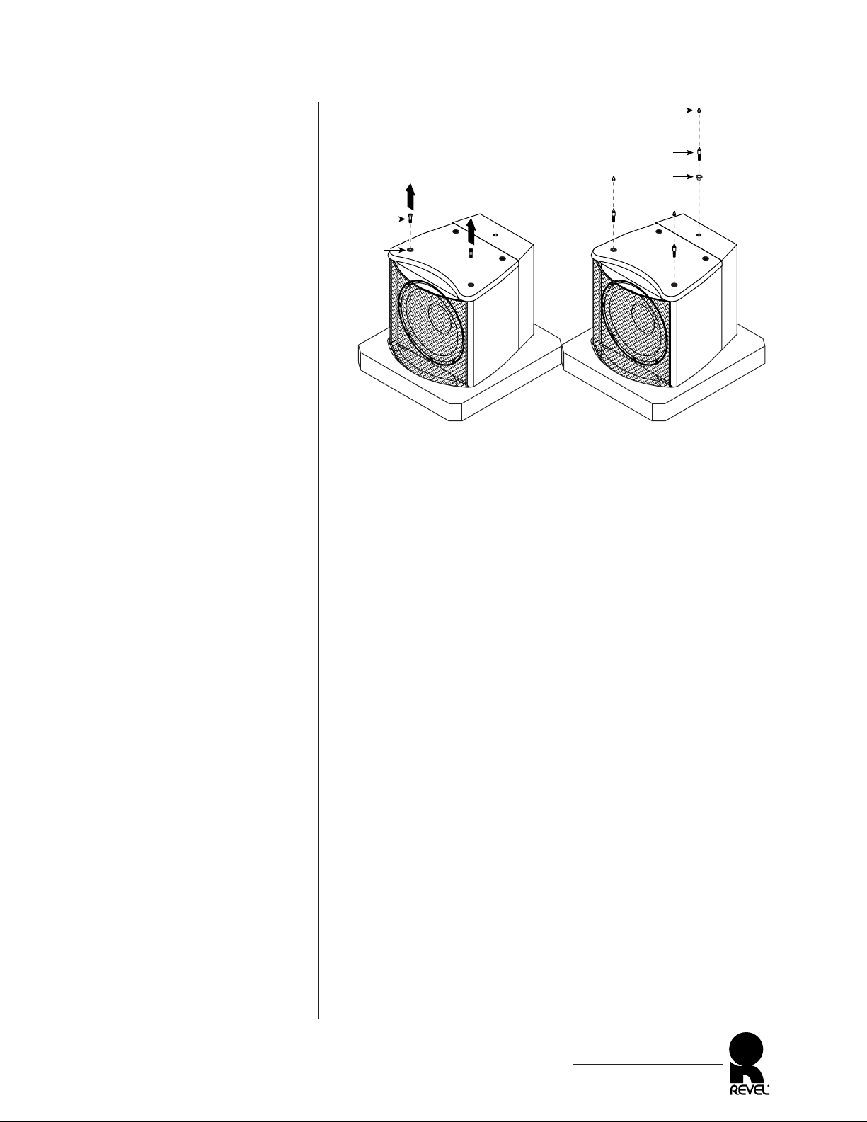
Figure 3.Installing spike feet
onto the ULTIMA
SUB-15 subwoofer.
3. Start the spike feet (with trim rings) by hand (see Figure 3)
and tighten them with the enclosed wrench.
4. For use on hard floors, install covers onto the spike feet using
the supplied adhesive. Wait 20 minutes for the silicone to set.
5. When finished, place the ULTIMA SUB-15 upright and
remove the top pad.
ULTIMA SUB-15/LE-1
Owner’s Manual
9
Trim
Ring
Top
Pad
SUB-15
(Bottom)
Bolt
Cover*
(optional for
hard floors)
Spike
Trim
Ring
Remove (2) Front Bolts;
Leave Trim Rings In Place
Install (3) Spikes (with Trim
Rings) Into Open Holes
*NOTE: Apply a small bead of
supplied silicone adhesive into each
cover and fasten onto each spike.
Wait 20 minutes for silicone to set.
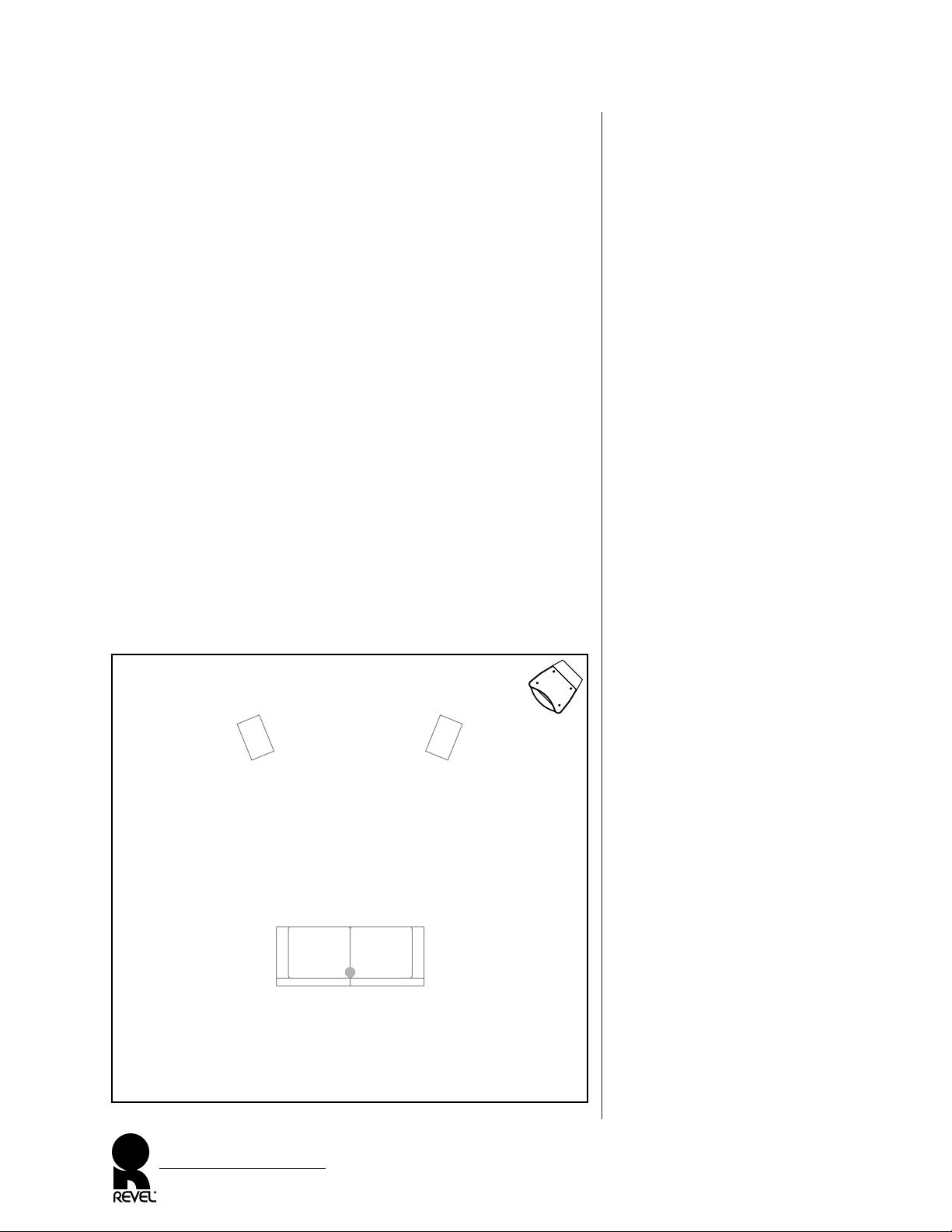
Figure 4. Typical placement
of a ULTIMA SUB-15 in an
average room.
PLACEMENT
SUB-15 PLACEMENT
Due to long wavelengths being reproduced, low-frequency bass
response from the ULTIMA SUB-15 is non-directional and, therefore, the subwoofer does not require specific placement location.
However, optimum results can be obtained by making in-room
measurements to determine the precise locations of all speakers in
your specific listening room. The location of a subwoofer, along
with the listener’s location, have a profound effect on sound quality.
Revel has made measurements in hundreds of listening rooms and
we suggest trying the following ideas to enhance performance:
• Use a corner placement for the ULTIMA SUB-15, as shown in
Figure 4 below. This will provide the smoothest response in
most rooms. If you cannot measure the response (in order to
find the best location), place the subwoofer in a front corner.
• If you plan to use two ULTIMA SUB-15s (see Figure 5 on
next page), place both subwoofers together in a front corner,
side-by-side or stacked, or place a subwoofer in each of the
front corners. However, if the room is not symmetrical, only
place the subwoofers together in one front corner.
ULTIMA SUB-15/LE-1
Owner’s Manual
10
Listening Position
(e.g., on couch)
SUB-15
L Speaker R Speaker
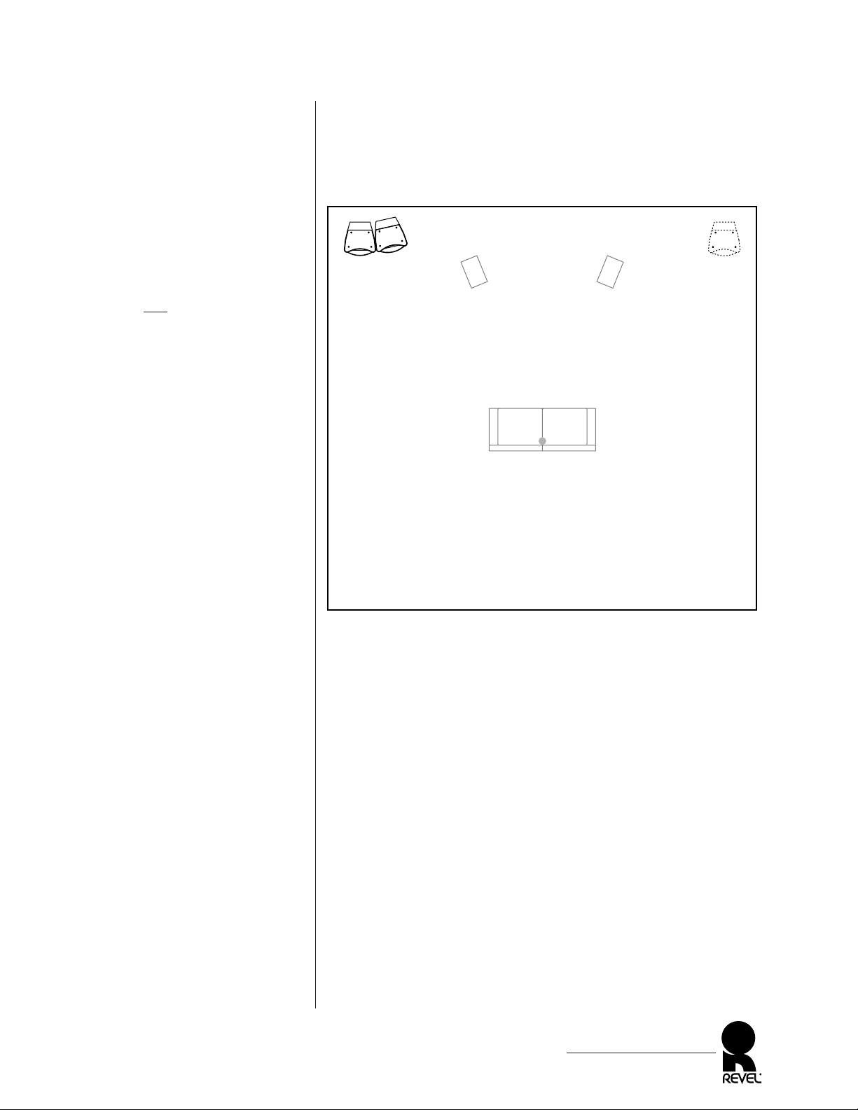
Figure 5. Preferred placement of
two ULTIMA SUB-15s in a
corner of a larger room.
NOTE: If the room is symmet-
rical and
the L/R speakers and
listening position are also sym-
metrical within the room, the
ULTIMA SUB-15s can be
placed in opposite corners (see
alternate placement).
• For very large rooms (e.g., over 3,000 cubic feet or 85 cubic
meters), consider adding another ULTIMA SUB-15 or another
ULTIMA LE-1/SUB-15 system for more bass output (see
Figure 5). Consult your Revel dealer for specific recommendations on your audio system.
• For best results, place the ULTIMA SUB-15 near solid walls to
reinforce bass response, and avoid windows which can rattle
and transmit sound to the outside world.
ULTIMA SUB-15/LE-1
Owner’s Manual
11
Listening Position
(e.g., on couch)
SUB-15SUB-15
L Speaker
(preferred placement) (alternate placement)
R Speaker

PLACEMENT (Continued)
LE-1 PLACEMENT
In a normal installation, the ULTIMA LE-1 receives its signals
from the preamplifier’s main output jacks and sends its signals (via
an internal crossover) to the ULTIMA SUB-15. To use the shortest
interconnect cables, place the ULTIMA LE-1 near the amplifier.
However, in doing so, please observe the following:
• To help dissipate internal heat, provide the ULTIMA LE-1
with adequate ventilation. Do not enclose the unit in an
unvented cabinet. Allow a minimum clearance of 4 to 6 inches
above the ULTIMA LE-1 and at least 2 inches on either side
for air flow.
• Place the ULTIMA LE-1 so its front panel is readily accessible
for viewing and control with the enclosed remote control.
• Provide convenient access to the ULTIMA LE-1’s rear panel to
allow for easy interconnection and later adjustment of system
controls (see System Optimization on page 25).
NOTE: Be sure to use adequate speaker cables to connect the
ULTIMA LE-1 and SUB-15(s). As an aid in determining the
maximum wire length for any gauge of speaker cable, please see
Figure 9 on page 18.
ULTIMA SUB-15/LE-1
Owner’s Manual
12
 Loading...