

Page 1

Revel®Ultima™Gem Loudspeakers
Page 2

TABLE OF CONTENTS
INTRODUCTION...............................................3
ABOUT THE MANUAL AND WARRANTY.................................3
DESCRIPTION .................................................4
WOOFERS ........................................................................4
TWEETERS........................................................................5
CROSSOVER NETWORK .....................................................5
CABINET...........................................................................5
UNPACKING....................................................6
INSTALLING STANDS (OPTIONAL) .....................7
PLACEMENT ...................................................9
ROOM ACOUSTICS...........................................................11
ROOM TREATMENT..........................................................12
CONNECTIONS..............................................13
SINGLE-WIRED SYSTEM CONNECTIONS ............................13
BI-WIRED SYSTEM CONNECTIONS ....................................14
BI-AMPLIFIED SYSTEM CONNECTIONS...............................15
SYSTEM OPTIMIZATION..................................17
CABINET CARE..............................................18
LOUDSPEAKERS AND POWER........................18
OBTAINING SERVICE......................................19
SPECIFICATIONS............................................20
REVEL ULTIMA GEM
Owner’s Manual
2
Page 3
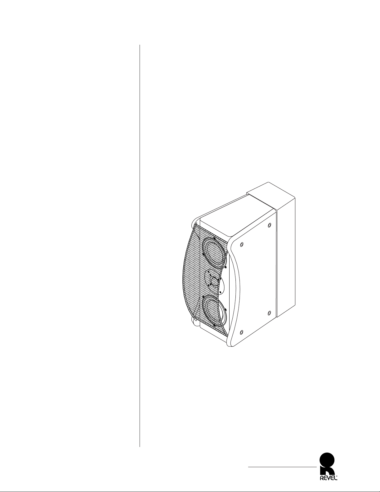
Figure 1. The REVEL
ULTIMA GEM loudspeaker.
INTRODUCTION
With its striking and sophisticated appearance, the REVEL®ULTIMA
™
GEM loudspeaker hints at its advanced design from the first glance.
The simple and clean lines characterize an exceptional sound reproduction system defined by its custom-designed drivers, individually
optimized crossover network, and a highly-functional enclosure.
We created these loudspeakers to achieve superior performance in
the widest possible range of environments. Physically small enough
to be used in modest rooms, they are dynamic enough to be used in
very large rooms. They are equally at home in discriminating twochannel systems, as well as multi-channel and home theater systems.
Moreover, we’ve taken the care to make them as adaptable as possible
to a variety of room positions and the acoustical interactions typically
found in homes.
ABOUT THE MANUAL AND WARRANTY
To begin enjoying your new loudspeakers, first read and then perform
the instructions in this owner’s manual. Maximum performance
depends on following all instructions described here, as well as those
found in the owner’s manuals of associated components in your audio
system. Save these instructions for future reference.
REVEL ULTIMA GEM loudspeakers are covered by a limited 5-year
warranty, so save the bill of sale to protect your purchase and aid in
any service-related questions.
REVEL ULTIMA GEM
Owner’s Manual
3
;
;
;;
;
;;;;
;;
;;
;
;;
;;;;;;;;;;
;
;
;;
;;
;;;
;
;;;;;;
;;;;;;;;;;
;
;
;;;
;
;;;
;;;;;;;;;
;
;
;
;
;
;;;
;
;;;;;;;;;;
;;;;;;;;
;
;
;;;
;
;;;;
;
;
Page 4
Figure 2. The REVEL
ULTIMA GEM transducer and
connection locations.
DESCRIPTION
The REVEL ULTIMA GEM loudspeaker features a unique transducer configuration (see Figure 2) to create an acoustic center that
is halfway between the two woofers and coincident with the front
tweeter’s acoustic center. A second tweeter (on rear of cabinet),
operating above 8 kHz, provides additional high-frequency energy
to enhance overall “room response.”
Combined with an individually-optimized crossover network, this
transducer arrangement provides a uniform vertical “listening window” or area in which the sound varies little. Also, the small
woofer size and compact baffle width help to create an extremely
wide horizontal window in which optimum sound can be heard.
WOOFERS
To ensure uncompressed dynamic range, each loudspeaker contains
a pair of 5-inch woofers that are unique in the following ways:
• The woofer’s radiating surface is made of titanium for true pistonic behavior to over 4 kHz, well beyond its function in the
GEM system.
• Optimized magnetic circuits to minimize harmonic distortion.
• The woofer’s motor system utilizes neodymium magnets with a
stray-flux containment system for shielding near video monitors.
• Oversized 2-inch diameter voice coils with flat aluminum wire
offer higher power handling than average-sized coils for greater
accuracy at high volume levels and during extended crescendos.
• The cast magnesium frame provides optimum voice coil cooling
and minimum reflections, while offering excellent rigidity.
REVEL ULTIMA GEM
Owner’s Manual
4
High Frequency
Input
High Frequency Level
(dB)
-1
Front
0
+.5
-.5
+1
-2
Rear
0
+4
0ff
Low Frequency
Input
Serial No.
In
s
t
a
l
l
S
t
r
a
p
s
f
o
r
S
i
n
g
le
-
w
i
r
e
d
O
p
e
r
a
t
io
n
.
I
n
s
t
a
l
l
S
t
r
a
p
s
f
o
r
S
i
n
g
le
-
w
i
r
e
d
O
p
e
r
a
t
io
n
.
Note:
Remove
Straps for
Bi-wired or
Bi-amplified
Operation.
Front
Tweeter
Port
High-Frequency
Level Controls
Connectors (with
shorting straps)
Rear
Woofer
Tweeter
Woofer
Northridge
California
Made in U.S.A.
Page 5

TWEETERS
Each loudspeaker also contains two high-performance tweeters
with the following features:
• Optimized tweeter-dome profiles for maximum dispersion,
while eliminating coloration caused by “break-up modes.”
• Linear reproduction with very-low harmonic distortion even at
high output levels for uncompressed sound purity.
• The front tweeter utilizes a large voice-coil with an oversized
surround roll. This provides for the higher power handling and
longer excursion capability required to reproduce greater
uncompressed dynamics.
CROSSOVER NETWORK
Built into each loudspeaker is an individually-optimized crossover
network with the following features:
• A 2-way, 24 dB per octave crossover at 2.7 kHz shapes the onand off-axis response of each driver and the complete system.
• Hand-wired filter networks with air-core inductors and
film capacitors are calibrated to match each loudspeaker to
the reference standard.
• Provision for bi-amplified and bi-wired applications via removable external shorting straps on the gold-plated binding posts.
• External level controls for both the front and rear tweeters via
calibrated switched precision resistors, thus maintaining identical response from both speakers for ideal imaging.
CABINET
The cabinet offers groundbreaking appearance and aids in overall
system performance. The inner enclosure is designed as an acoustically-inert platform for sound-wave generation. Integral side panels
provide a custom look via available finishes and are internally
damped by sandwiched viscoelastic energy-absorbing layers to
reduce any sound transmission effects.
REVEL ULTIMA GEM
Owner’s Manual
5
Page 6
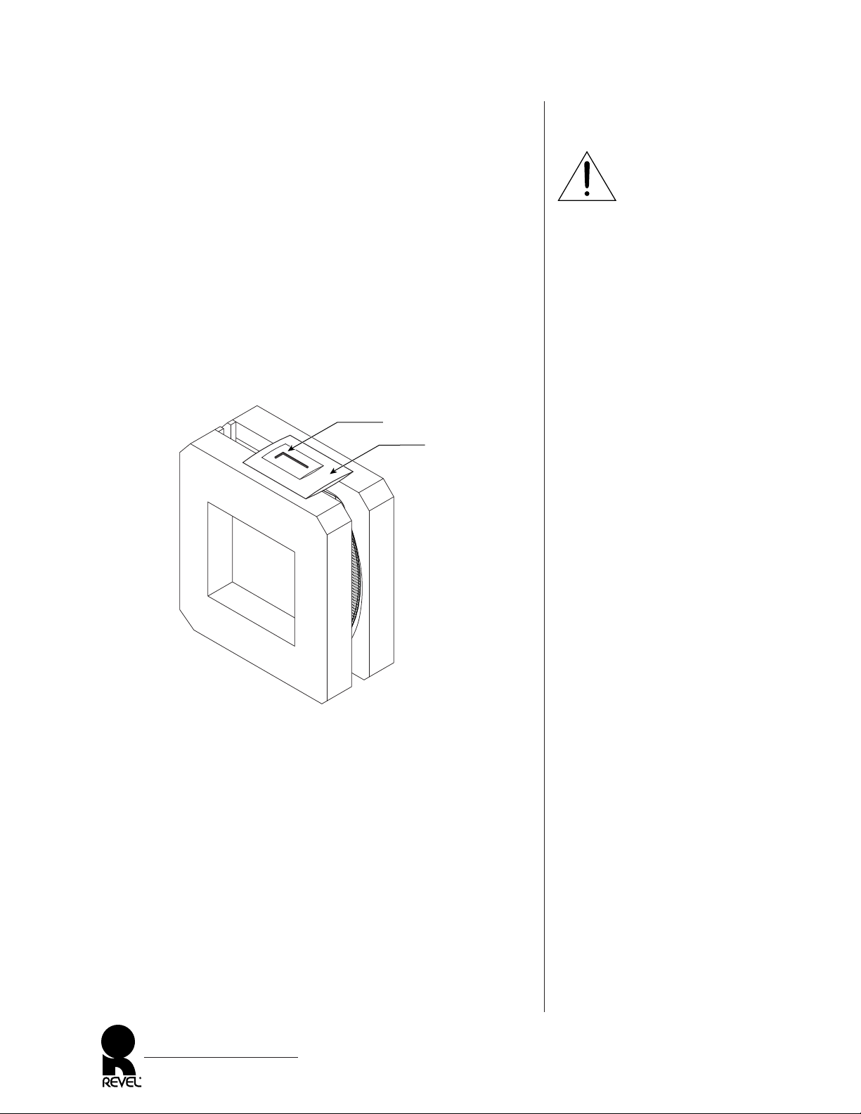
Figure 3. A REVEL
ULTIMA GEM loudspeaker
with its inner packing materials.
UNPACKING
To avoid injury, please use care during unpacking. Always
stand as straight as possible and use your leg muscles to lift a
REVEL ULTIMA GEM loudspeaker. Do not lift it while bending from the waist.
To unpack a REVEL ULTIMA GEM loudspeaker, perform the
following steps:
1. Place a REVEL ULTIMA GEM loudspeaker onto its side.
2. Open the bottom flaps. Stand the carton in the up position.
3. Lift the carton off the loudspeaker and set it aside, being careful
not to damage the contents (see Figure 3).
4. Remove the allen wrench and set it aside.
5. Remove the left and right pads and the protective cloth. Use
caution to avoid scraping the finish or pulling off the grille.
After unpacking the unit, carefully inspect it for possible damage
due to shipping. If you discover any damage, immediately contact
your Revel dealer for further assistance. When moving a REVEL
ULTIMA GEM loudspeaker (e.g., when experimenting with placement), avoid touching the transducers.
Keep all packing materials for future shipping. In the unlikely
event a product will need repair, Revel will only accept a unit in its
original shipping carton. Using any other packing materials may
result in damage to the product and is not covered by the warranty.
See Obtaining Service on page 19 for additional details.
REVEL ULTIMA GEM
Owner’s Manual
6
Allen Wrench
Left Pad
Right Pad
Warranty Card and
Owner’s Manual
WARNING
Page 7
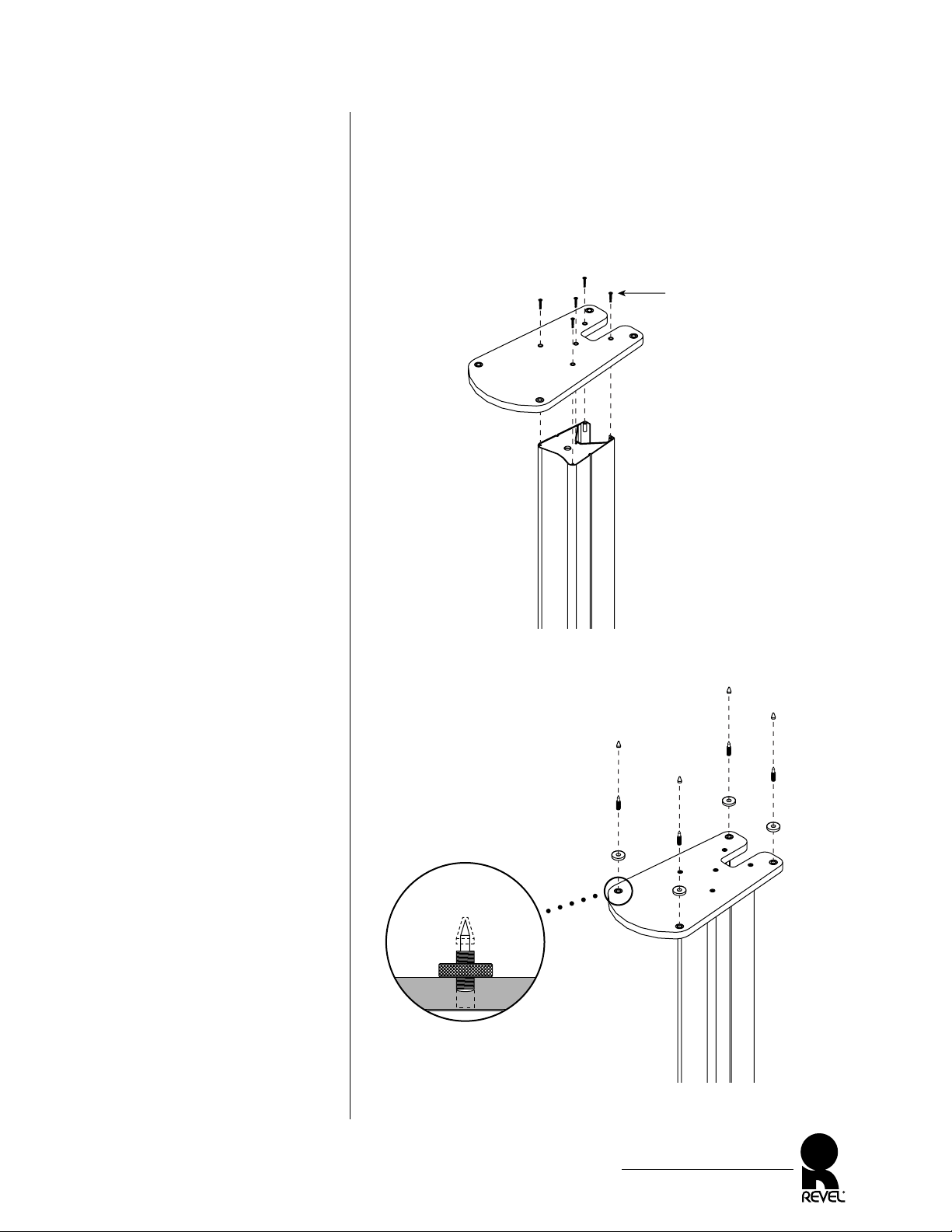
Figure 4. Installing the base
onto the pedestal.
Figure 5. Installing spikes.
INSTALLING STANDS (OPTIONAL)
1. Unpack all stand boxes. Place a pedestal, base, and top plate on
a soft surface (e.g, rug or soft cloth).
2. Using a Phillips screwdriver, install a base to a pedestal with five
long screws, as shown in Figure 4.
3. Thread four spikes about halfway into the base and tighten each
one with a locking ring, as shown in Figure 5.
continued on next page...
REVEL ULTIMA GEM
Owner’s Manual
7
Pedestal
Base
(5) Long Screws
(Start All Screws
Before Tightening)
(4) Spikes
(4) Covers*
(optional for hardwood
or tile floors)
(Optional) Use Covers*
For Hard Floors
(4) Locking
Rings
*NOTE: Apply a small bead of supplied
silicone adhesive into each cover and
fasten onto each spike. Wait 20 minutes
for silicone to set.
Page 8
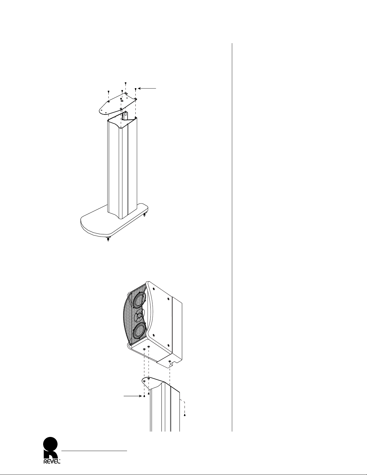
Figure 6. Installing the top plate.
Figure 7. Fastening the REVEL
ULTIMA GEM loudspeaker to
the assembled stand.
INSTALLING STANDS (CONT’D)
4. Place the stand in its upright position and install the top plate
with five short screws, as shown in Figure 6.
5. Fasten a loudspeaker to the stand with three short screws, as
shown in Figure 7. Read the Placement section before making
final placement and spike adjustments. Repeat steps 1 through 5
for the other stand.
REVEL ULTIMA GEM
Owner’s Manual
8
(5) Short Screws
(Start All Screws
Before Tightening)
Top Plate
REVEL ULTIMA GEM
(3) Short Screws
(Start All Screws
Before Tightening)
Page 9

Figure 8. A REVEL ULTIMA
GEM loudspeaker is placed
on an optional stand for an
ideal match between tweeter
and ear heights.
Figure 9. Typical placement of
REVEL ULTIMA GEM
loudspeakers for stereo.
NOTE: The suggested room
treatments coincide with the
primary reflection points.
PLACEMENT
Sound quality is heavily dependent on the accuracy of your loudspeakers, their placement in the listening room, and the acoustics of the
room itself. Since the REVEL ULTIMA GEM loudspeakers are
extremely accurate, experimenting with their placement is the most
significant way to optimize their performance in a given environment.
The following guidelines will help you obtain the best results:
• In most situations, we recommend placing the REVEL
ULTIMA GEM loudspeakers on their (optional) matching
stands, as shown in Figure 8.
NOTE: When experimenting with placement, we recommend that
two people move a REVEL ULTIMA GEM loudspeaker (with its
attached stand) by lifting under the stand’s top plate.
• For best stereo imaging, place the REVEL ULTIMA GEM
loudspeakers at equal distances from the main listening position
and in symmetry with the room, as shown in Figure 9.
continued on next page...
REVEL ULTIMA GEM
Owner’s Manual
9
Listening Position
(e.g., on couch)
Absorptive or
Diffusive
Material
Absorptive or Diffusive Material
Absorptive or Diffusive Material
Absorptive or
Diffusive
Material
Absorptive or
Diffusive
Material
R REVEL ULTIMA GEM
L REVEL ULTIMA GEM
GEM Tweeter
Page 10

PLACEMENT (CONTINUED)
• Optimum timbre and imaging precision is obtained with the
loudspeakers pointing almost directly toward the prime listening position. Some listeners prefer a wider “soundstage,” which
is achieved by reducing the toe-in angle, perhaps to the point of
aiming the loudspeakers straight ahead.
• Imaging and a sense of spaciousness will improve as the
loudspeakers are moved away from the wall behind the loudspeakers and the side walls.
NOTE: You may then need to move the listening position back to
maintain the best stereo image.
• For more bass reinforcement, try moving the loudspeakers closer
to the front wall or corners (also see Room Acoustics on next page).
NOTE: You may then need to move the listening position forward
to maintain an acceptable stereo image.
• For best results, make sure there are no objects between the
REVEL ULTIMA GEM loudspeakers and the intended listening
area (e.g., a coffee table in front of the listener will degrade timbre
and imaging). If possible, avoid placing the loudspeakers near
large objects, which can cause unwanted reflections.
• Ideally, the listening room should be acoustically neutral, neither producing any distinct echoes nor sounding completely
“dead” and lifeless (also see Room Treatment on page 12).
REVEL ULTIMA GEM
Owner’s Manual
10
Page 11

ROOM ACOUSTICS
Listening rooms have a profound impact on sound quality, especially at low frequencies. In fact, a listening room can actually
dominate the sound quality below about 300 Hz. Ideally, a new
room being built from scratch would include optimized dimensional ratios to minimize the effects of standing waves.
However, most installations will be made in existing rooms. In
these cases, your only solution is to take special care in selecting
both the speaker and prime listening locations, which will pay off
in superior low frequency performance. Often the difference
between poor and excellent results is the result of relatively small
adjustments in speaker and listener placements.
The interaction of loudspeakers and rooms is quite complex, as the
loudspeaker and listener are affected by two mechanisms. First,
nearby surfaces, or boundaries, cause large peaks and dips in low
frequency response. These peaks and dips can often range 12 dB or
more. Second, the loudspeaker and listener locations interact with
the standing waves, or room modes. These standing waves, or resonances, also result in large response errors. There are no simple formulas that take both mechanisms into account. Even computer
programs that analyze one or both factors still may not provide
you with the proper speaker or listener placement values.
Here’s where real-world experience counts. We suggest consulting
your Revel dealer for help in determining the optimum loudspeaker and listener placement for your listening room.
REVEL ULTIMA GEM
Owner’s Manual
11
Page 12

PLACEMENT (CONTINUED)
ROOM TREATMENT
REVEL ULTIMA GEM loudspeakers have very accurate off-axis
response, which minimizes any degradation caused by overly “live”
rooms. However, far superior performance will be achieved by
placing at least minimal acoustic treatment materials at the primary
reflection points. Ideally, special acoustic absorbers or diffusers
should be placed at the first reflection points on the side and front
walls along with either absorbers or diffusers at the first reflection
points on the rear wall. Short of using acoustic treatment materials,
even simple hanging rugs can be a great help in overly bright
rooms. Carpeting the floor area between the speakers and listener
and placing irregular surfaces, such as bookcases, will also help
break up strong reflections.
Since our ears and eyes are located on the same plane, we can use a
mirror (also known as the “mirror method”) to accurately determine the most important locations (the first reflection points) for
material treatment, as follows:
1. After the loudspeakers are placed, the listener should sit in the
prime listening position.
2. A second person should slide a mirror along the walls.
3. Note the locations at which the listener can see either of the
loudspeakers. These will be the reflection points that would
require acoustic treatment materials.
Using this method, find all treatment locations for side walls, front
wall, and rear wall with side walls taking priority. Where possible,
also determine the treatment locations for first ceiling reflections.
Your Revel dealer can recommend acoustic treatment materials,
and can help determine the best plan for your room. If it is a
dedicated listening room, qualified room treatment manufacturers
or even acousticians may be consulted for optimum results.
Remember, properly treated rooms provide dramatically better
results with any loudspeakers than untreated rooms.
REVEL ULTIMA GEM
Owner’s Manual
12
Page 13

Figure 10. Wire gauge versus
maximum wire run (with a
maximum loop resistance of
0.07 ohms) for less than 0.2 dB
response error.
NOTE: “Loop resistance” is the
DC resistance measured at one
end of a loudspeaker cable, with
the other ends shorted together.
CONNECTIONS
REVEL ULTIMA GEM loudspeakers can be connected to an audio
system in three different ways: single-wired, bi-wired or bi-amplified.
Please read the following sections before proceeding with actual connections. Also, be sure to observe the following points:
• Use high-quality speaker cable with a maximum total loop resistance (for each wire run) of 0.07 ohms or less. Use the chart in
Figure 10 below to determine the maximum wire gauge.
A high loop resistance will result in mis-termination of the
filter networks, and serious degradation of sound quality.
Use high-quality connectors on the loudspeaker cables. Consult
your Revel dealer as to specific solutions for your application.
• Turn off all audio system power before making any connections.
• Read the owner’s manuals that were included with your audio
components to confirm their connection procedures.
• Verify correct polarities (i.e., + to + and − to −) when making
connections. Failure to do so will cause poor imaging and
diminished bass response.
• For bi-wired or bi-amplified applications, remove the shorting
straps (see Figures 12, 13, and 14 on the next three pages).
SINGLE-WIRED SYSTEM CONNECTIONS
For most applications, simply leave the shorting straps in place and
connect the + and − from a single amplifier channel to the HIGH
FREQUENCY INPUT terminals, as shown in Figure 11 (on the
next page).
REVEL ULTIMA GEM
Owner’s Manual
13
W
IRE GAUGE (AWG) LENGTH (FEET)LENGTH (METERS)
68727
76921
85818
94313
10 34 10
11 27 8
12 22 7
13 17 5
14 14 4
15 11 3
16 9 3
17 7 2
18 5 2
IMPORTANT
Page 14

Figure 11. How to connect
the REVEL ULTIMA GEM
loudspeaker in a single-wired
system, the most common type
of installation.
Figure 12. How to connect
the REVEL ULTIMA GEM
loudspeaker in a bi-wired system.
CONNECTIONS
SINGLE-WIRED SYSTEM CONNECTIONS (CONT’D)
BI-WIRED SYSTEM CONNECTIONS
A bi-wired system involves two pairs of speaker wires connected to
a single amplifier channel. Remove the shorting straps and connect
the + and − of one pair of wires to the HIGH FREQUENCY
INPUT terminals and the + and − of the other pair of wires to the
LOW FREQUENCY INPUT terminals, as shown in Figure 12.
Check with your Revel dealer for recommendations and possible
benefits for your application.
REVEL ULTIMA GEM
Owner’s Manual
14
redwhite
redwhite
GEM Rear
Connector
Panel
High Frequency
Input
High Frequency Level
(dB)
-1
Front
0
+.5
-.5
+1
-2
Rear
0
+4
0ff
Low Frequency
Input
Serial No.
In
s
t
a
ll
S
t
r
a
p
s
fo
r
S
in
g
le
w
ir
e
d
O
p
e
r
a
t
i
o
n
.
I
n
s
t
a
l
l
S
t
r
a
p
s
f
o
r
S
i
n
g
l
e
-
w
i
r
e
d
O
p
e
r
a
t
i
o
n
.
Note:
Remove
Straps for
Bi-wired or
Bi-amplified
Operation.
Northridge
California
Made in U.S.A.
Shorting Straps
Removed
Amplifier
(rear)
(one channel shown)
High Frequency
Input
High Frequency Level
(dB)
-1
Front
0
+.5
-.5
+1
-2
Rear
0
+4
0ff
Low Frequency
Input
Serial No.
Northridge
California
Made in U.S.A.
Shorting Straps
(leave in place)
redwhite
GEM Rear
Connector
Panel
High Frequency
Input
High Frequency Level
(dB)
-1
Front
0
+.5
-.5
+1
-2
Rear
0
+4
0ff
Low Frequency
Input
Serial No.
In
s
t
a
ll
S
t
r
a
p
s
fo
r
S
i
n
g
le
-w
ir
e
d
O
p
e
r
a
t
io
n
.
I
n
s
t
a
l
l
S
t
r
a
p
s
f
o
r
S
i
n
g
l
e
-
w
i
r
e
d
O
p
e
r
a
t
i
o
n
.
Note:
Remove
Straps for
Bi-wired or
Bi-amplified
Operation.
Northridge
California
Made in U.S.A.
Amplifier
(rear)
(one channel shown)
High Frequency
Input
High Frequency Level
(dB)
-1
Front
0
+.5
-.5
+1
-2
Rear
0
+4
0ff
Low Frequency
Input
Serial No.
In
sta
ll S
trap
s fo
r
S
in
g
le
-w
ire
d
O
p
era
tio
n
.
In
s
t
a
l
l
S
t
r
a
p
s
f
o
r
S
in
g
le
-
w
ir
e
d
O
p
e
r
a
t
io
n
.
Northridge
California
Made in U.S.A.
Page 15

Figure 13. How to connect
the REVEL ULTIMA GEM
loudspeaker in a vertical
bi-amplified system.
BI-AMPLIFIED SYSTEM CONNECTIONS
A bi-amplified system provides increased sonic performance,
since independent amplifier channels separately drive each set of
high- and low-frequency transducers. You can connect the loudspeakers in either a vertical or horizontal bi-amplified system
without requiring an additional electronic crossover.
VERTICAL BI-AMPLIFIED SYSTEM
Using two identical amplifier channels, remove the shorting straps
from the rear panel; then connect the loudspeakers as shown in
Figure 13.
Failure to remove the shorting straps when bi-amplifying may
damage some amplifiers.
NOTE: When using two dissimilar amplifiers, connect the loudspeakers
in a horizontal bi-amplified system (see the next section).
REVEL ULTIMA GEM
Owner’s Manual
15
redwhite
redwhite
GEM Rear
Connector
Panel
High Frequency
Input
High Frequency Level
(dB)
-1
Front
0
+.5
-.5
+1
-2
Rear
0
+4
0ff
Low Frequency
Input
Serial No.
In
s
ta
ll S
t
r
a
p
s
f
o
r
S
i
n
g
le
-w
ir
e
d
O
p
e
r
a
t
io
n
.
I
n
s
t
a
l
l
S
t
r
a
p
s
f
o
r
S
i
n
g
l
e
-
w
i
r
e
d
O
p
e
r
a
t
i
o
n
.
Note:
Remove
Straps for
Bi-wired or
Bi-amplified
Operation.
Northridge
California
Made in U.S.A.
Shorting Straps
Removed
Amplifier
(rear)
Ch. 1 Ch. 2
(one channel shown)
(one channel shown)
(Optional “Y” Adaptor)
INPUT INPUT
Pre-Amplifier
(rear)
OUTPUTOUTPUT
High Frequency
Input
High Frequency Level
(dB)
-1
Front
0
+.5
-.5
+1
-2
Rear
0
+4
0ff
Low Frequency
Input
Serial No.
Northridge
California
Made in U.S.A.
WARNING
Page 16

Figure 14. How to connect
the REVEL ULTIMA GEM
loudspeaker in a horizontal
bi-amplified system.
CONNECTIONS
BI-AMPLIFIED SYSTEM CONNECTIONS (CONT’D)
HORIZONTAL BI-AMPLIFIED SYSTEM
Using two amplifier channels, remove the shorting straps from the
rear panel; then connect the loudspeakers as shown in Figure 14.
Failure to remove the shorting straps when bi-amplifying may
damage some amplifiers.
NOTE: If the “gain factor” of the two amplifier channels is not identical, a means of adjusting the input level of at least one of the channels
is required. Consult your Revel dealer for specific recommendations.
REVEL ULTIMA GEM
Owner’s Manual
16
redwhite
redwhite
GEM Rear
Connector
Panel
Shorting Straps
Removed
(one channel shown –
use for high frequencies)
(one channel shown –
use for low frequencies)
Amplifier
(rear)
INPUT
Amplifier
(rear)
INPUT
High Frequency
Input
High Frequency Level
(dB)
-1
Front
0
+.5
-.5
+1
-2
Rear
0
+4
0ff
Low Frequency
Input
Serial No.
Northridge
California
Made in U.S.A.
High Frequency
Input
High Frequency Level
(dB)
-1
Front
0
+.5
-.5
+1
-2
Rear
0
+4
0ff
Low Frequency
Input
Serial No.
In
s
t
a
ll
S
t
r
a
p
s
fo
r
S
in
g
le
-w
ir
e
d
O
p
e
r
a
t
io
n
.
I
n
s
t
a
l
l
S
t
r
a
p
s
f
o
r
S
i
n
g
l
e
-
w
i
r
e
d
O
p
e
r
a
t
i
o
n
.
Note:
Remove
Straps for
Bi-wired or
Bi-amplified
Operation.
Northridge
California
Made in U.S.A.
(one channel shown)
(Optional “Y” Adaptor)
Pre-Amplifier
(rear)
OUTPUTOUTPUT
WARNING
Page 17

Figure 15. The REVEL
ULTIMA GEM level control
locations and initial settings.
SYSTEM OPTIMIZATION
After connecting the REVEL ULTIMA GEM loudspeakers,
initially set both HIGH FREQUENCY LEVEL controls on the
rear panel to the “0” position (see Figure 15).
1. Turn on the system power and play a favorite piece of music.
Slowly increase the volume to a comfortable level and listen
from your main listening position. Experiment with placement
(see page 9), as it will pay off in optimized tonal balance, image
specificity, and spaciousness.
2. You may also wish to further adjust the HIGH FREQUENCY
LEVEL controls (see Figure 15) for both front and rear tweeters to achieve the most natural sound in your room. Varying
the FRONT control will change the high frequency balance
and timbre. Varying the REAR control will mainly affect “air”
and spaciousness.
NOTE: Be certain the corresponding controls are set the same on
both left and right channels.
REVEL ULTIMA GEM
Owner’s Manual
17
GEM Rear
High Frequency
Input
High Frequency Level
(dB)
-1
Front
0
+.5
-.5
+1
-2
Rear
0
+4
0ff
Low Frequency
Input
Serial No.
In
s
t
a
ll S
tr
a
p
s
fo
r
S
in
g
le
-w
i
re
d
O
p
e
r
a
tio
n
.
I
n
s
t
a
l
l
S
t
r
a
p
s
f
o
r
S
i
n
g
l
e
-
w
i
r
e
d
O
p
e
r
a
t
i
o
n
.
Note:
Remove
Straps for
Bi-wired or
Bi-amplified
Operation.
Northridge
California
Made in U.S.A.
High Frequency
Input
Low Frequency
Input
Serial No.
Install Straps for
Single-w
ired
O
peration.
Install Straps for
Single-wired
Operation.
Note:
Remove
Straps for
Bi-wired or
Bi-amplified
Operation.
Northridge
California
Made in U.S.A.
High Frequency Level
(dB)
-1
Front
0
+.5
-.5
+1
-2
Rear
0
+4
0ff
Set High-Frequency
Level Controls
To “0”
Connector Panel
Page 18

CABINET CARE
Each REVEL ULTIMA GEM loudspeaker cabinet has a paint finish and does not require any routine maintenance. Use a soft cloth,
dampened with water only, to remove any fingerprints or to wipe
off dust. Clean the grille by gentle vacuuming.
For wood side panels, occasionally use a household furniture polish
to maintain the beauty of the hardwood veneers. For aluminum
side panels, use a soft cloth, dampened with soapy water only.
SPEAKERS AND POWER
REVEL ULTIMA GEM loudspeakers use high-order crossovers
with steep cut-offs to eliminate damage caused by “out of band”
frequencies. Using this approach, in combination with carefully
selected components and transducers, gives us confidence that a
REVEL ULTIMA GEM loudspeaker will not fail, even under
extreme conditions.
However, there is a limit to how loud any speaker can play continuously. A good rule of thumb is to avoid playing the system at volume levels beyond where the sound is “clear.” If the sound becomes
distorted or strained, reduce the volume level immediately to
avoid damage.
If you are unsure of the suitability of current or planned amplifier
components, please ask your Revel dealer to review them before
connecting your REVEL ULTIMA GEM loudspeakers.
REVEL ULTIMA GEM
Owner’s Manual
18
Page 19

OBTAINING SERVICE
We take great pride in our dealers. Experience, dedication, and
integrity make these professionals ideally suited to assist with our
customers’ service needs.
If your Revel component requires service, please contact your dealer.
Your dealer will then decide whether the problem can be remedied
locally, or whether to contact Revel for further service information or
parts, or to obtain a Return Authorization. If needed, call the Revel
Service Department at:
1-818-830-8777 on any business day, from 9
A.M. to 5 P.M. PST.
The Revel Technical Services Department works closely with your
dealer to solve your service needs expediently.
Return authorization must be obtained from Revel’s Technical
Services Department BEFORE a unit is shipped for service.
It is extremely important that information about a problem be
explicit and complete. A specific, comprehensive description of the
problem helps your dealer and the Revel Technical Services
Department locate and repair the difficulty as quickly as possible.
A copy of the original bill of sale will serve to verify warranty status.
Please include it with the component when it is brought in for
warranty service.
All returned units must be properly packaged in their original
packing material, and the proper return authorization numbers
must be marked on the outer carton for identification. If the
packaging to protect the unit is, in our opinion or that of our
dealer, inadequate to protect the unit, we reserve the right to
repackage it for return shipment at the owner’s expense. Neither
Revel nor your dealer can be responsible for shipping damage
due to improper (i.e., non-original) packaging.
Your dealer can order a new set of shipping materials for you if you
need to ship your component and no longer have the original
materials, or if they are in poor condition. There will be a charge
for this service. We strongly recommend saving all packing materials in case you need to ship your unit some day.
REVEL ULTIMA GEM
Owner’s Manual
19
IMPORTANT
WARNING
Page 20

SPECIFICATIONS
Revel utilizes proprietary measurement methods in the design and
specification of our loudspeakers. Our research has developed a
series of tests that represent a great leap forward in making measurements that dramatically contribute to our goal of accurately
reproducing music or film.
Sensitivity: 87.0 dB SPL, with 2.83 V
rms
@ 1 m
(4 pi anechoic)
Sensitivity provides an indication of how much amplifier power is required
for the loudspeaker to play at satisfactory volume levels. This conservativelyrated specification indicates moderate sensitivity and denotes that the
REVEL ULTIMA GEM loudspeaker does not require huge amplifiers to
achieve realistic levels in all but the largest rooms.
Impedance: 6 ohms (nominal), 3 ohms (minimum)
@ 115 Hz
Impedance indicates whether the speaker system presents a “hard”
or “easy” load on the amplifier. A minimum impedance value of
3 ohms, together with moderate phase angles, signifies that any
competently-designed amplifier can easily drive the REVEL ULTIMA
GEM loudspeaker.
Filters (Crossover): 2-way, 24 dB @ 2.7 kHz
The steep filter slopes ensure good acoustical behavior in the
crossover regions, with a minimum of acoustical interference, along
with low distortion and wide dynamic range. The filters feature
specially selected components. Woofer and tweeter filter boards are
physically independent.
Frequency Responses: In-Room Response;
±1.5 dB from 77 Hz to 18 kHz
In-room response is a breakthrough measurement that, in a single
curve, closely correlates to sound quality and has been a goal of loudspeaker engineers for years. Research, and simple observation, reveals
that ubiquitous “on-axis” response curves often cannot distinguish
between two loudspeakers with radically different sound quality.
This REVEL ULTIMA GEM loudspeaker specification is even more
powerful when it is taken in context with the other measurements
presented here.
In-Room Response Relative to Target Response;
±1.0 dB from 70 Hz to 20 kHz
A target response is the ideal response goal and is not flat at the frequency extremes and is used when the ideal reference is not a “flat”
line. A target response must be tailored to the loudspeaker’s intended
application and takes into account the acoustic impact of the loudspeaker’s location, such as freestanding, or placement near a wall.
First-Reflections Response;
±1.5 dB from 77 Hz to 16 kHz
First reflection response is a measure of the response a listener
hears that is contributed by the first reflections from the walls,
floor, and ceiling. This superb specification indicates that REVEL
ULTIMA GEM loudspeaker will remain accurate, even in the presence of strong reflections.
REVEL ULTIMA GEM
Owner’s Manual
20
Page 21

Figure 16. Overall dimensions
for the REVEL ULTIMA
GEM loudspeaker and its
optional stand.
SPECIFICATIONS (CONTINUED)
Frequency Responses: Listening Window Response;
(continued) ±1.0 dB from 85 Hz to 17 kHz
This improved “on-axis” measurement reduces the visual confusion
of inaudible local interference, yet still retains full accuracy without
using “spectral smoothing” which results in significant data loss.
Low Frequency Extension;
-3 dB @ 61 Hz (-6 dB @ 47 Hz, -10 dB @ 38 Hz)
Studies have shown that the -10 dB low frequency extension specification is the one that best correlates to controlled listening tests. At low
frequencies, most loudspeaker/room combinations will exhibit significant “room gain”, which is an increasing rise in level as frequencies
decrease. In addition, the -10 dB specification reflects the steepness
(i.e., order) of the low-frequency roll-off, which is not significantly
indicated in -3 dB specifications.
Dimensions: 191⁄ 2"H x 83⁄ 8" W x 173⁄8"D
495 mm H x 213 mm W x 441 mm D
(with side panels and grille – see Figure 16 below)
Weight: 44 lb (20 kg), wood panels, net weight
59 lb (27 kg), aluminum panels, net weight
Revel, a division of Madrigal Audio Laboratories, constantly strives to update and improve existing products, as well
as create new ones. Therefore, the specifications and construction details in this and related Revel publications are
ubject to change without notice. Ultima is a trademark and Revel is a registered trademark of Harman International
Industries, Inc. © Harman International, 2000.
REVEL ULTIMA GEM
Owner’s Manual
21
17-3⁄ 8"
(440.9 mm)
8-3 ⁄ 8"
(212.2 mm)
20"
(508.0 mm)
19-1⁄ 2"
(495.3 mm)
29-5 ⁄ 8"
(752.5 mm)
49-1⁄8"
(1,247.8 mm)
11-7 ⁄16 "
(290.4 mm)
28-1⁄ 8"
(714.4 mm
27"
(685.8 mm)
3 ⁄ 16 "
(4.8 mm)
15 ⁄16 "
(23.9 mm)
1-1 ⁄ 2"
(38.1 mm)
Page 22

Page 23

Page 24

P/N 9301574-001
8500 B
ALBOA BOULEVARD
N
ORTHRIDGE, CA 91329
PH: (818) 830-8777 • FAX: (818) 892-4960
www.revelspeakers.com
 Loading...