

Page 1

MODERN SOUND FOR YOUR CLASSIC
www.retromanufacturing.com
USER’S MANUAL, MOTOR 2
TM
Page 2
1
TABLE OF CONTENTS
WELCOME 2
WHAT’S IN THE BOX 3
PRECAUTIONS 4
INSTALLATION INSTRUCTIONS 7
WIRING DIAGRAM 10
OPERATING YOUR RADIO
GENERAL OPERATION 14
TONE CONTROLS 17
SYSTEM SETTINGS 18
USB DEVICE INSTRUCTIONS 22
BLUETOOTH® INSTRUCTIONS 24
TROUBLESHOOTING 26
FREQUENTLY ASKED QUESTIONS 27
SPECIFICATIONS 30
LIMITED WARRANTY 31
REPLACEMENT PARTS 32
INSTALLATION NOTES 33
Page 3
2
Copyright © 2019 Retro Manufacturing, LLC
WELCOME
Thank you for purchasing a RetroSound
®
Apache RetroRadioTM.
Apache has the advanced features you expect from a modern
car stereo.
General Features
• Built-in Bluetooth® for hands-free calling and audio streaming
• Selectable 32,000 color LCD illumination with user pre-sets
• AM/FM tuner with 30 pre-sets
• Plays MP3, WMA and FLAC les via USB input
• Selectable international tuner frequencies
• Built-in amplier with TRUE 25 watts RMS x 4-channels
(45 watts peak x 4-channels)
• 3 EQ pre-sets plus user-controlled bass, mid-range,treble, fader, and
balance adjustments
• InniMount bracket system for maximum installation exibility
• Available with period-correct knobs, bezel and/or faceplate
• Inputs: 1 rear-mounted standard USB port and 2 rear auxiliary inputs
• Outputs: 4-channel pre-amp outputs (front, rear)
• Separate power antenna and amplier turn-on lead(s)
• 1 year parts and labor warranty
The information enclosed in this user’s manual is to be used as a guide to assist
you with installation and operation of your radio. This guide does not cover
every installation possibility, vehicle, or every aspect of the installation process.
Retro Manufacturing, LLC, RetroSound®, or its subsidiaries, assume no
responsibility for any installation. This manual may be updated from time to time.
Visit our website for the latest updates: www.retromanufacturing.com.
The Bluetooth® word mark and logos are registered trademarks owned by Bluetooth SIG,
Inc. and any use of such marks by Retro Manufacturing, LLC is under license.
Page 4
3
WHAT’S IN THE BOX
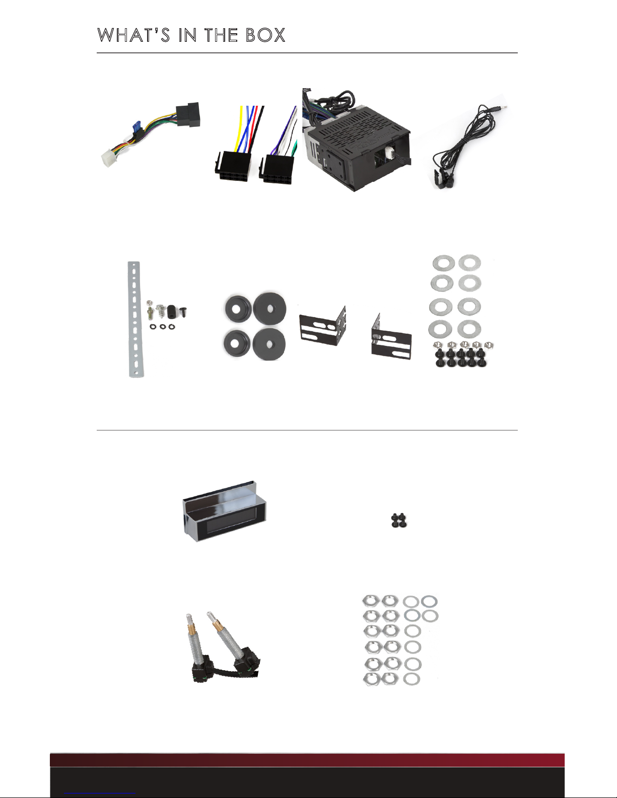
The items shown below are packaged with your Motor box.
The items shown below are packaged with your RetroRadioTM face box.
Main Wiring Harness
(plugs into back of radio)
Power and Speaker
Wiring Harnesses
(both plug into
Main Wiring Harness)
Motor 2 Radio Body Bluetooth® Microphone
RetroRadioTM Face
Shaft Mounting Hardware
Radio Face
Mounting Screws
Shafts
InniMount Brackets
Metal Mounting Backstrap
and Hardware
Plastic Washer Kit
Bracket Mounting Hardware
Page 5
4
Copyright © 2019 Retro Manufacturing, LLC
PRECAUTIONS
PLEASE OBSERVE THESE PRECAUTIONS WHEN INSTALLING
AND USING THIS UNIT:
This user’s manual does not cover all possible installation scenarios.
If you feel that you can’t install this unit yourself take it to a local
car audio professional. If you have questions about installing your
radio contact us at [email protected] or by calling us
at 888.325.1555.
• Do not disassemble, modify the unit or attempt to repair the
unit yourself. If the unit needs to be repaired, consult your
dealer or Retro Manufacturing, LLC.
• Do not use the unit when it is out of order. If the unit is out of
order or is in an abnormal state (has foreign objects in it, is
exposed to water, smokes or smells), turn it off immediately
and consult your dealer or Retro Manufacturing, LLC.
• Refer fuse replacement to qualied service personnel. If the
fuse fails, eliminate the cause and have it replaced by a
qualied service technician with the fuse prescribed for this
unit. Incorrect replacement of the fuse may lead to smoke, re
or damage to the unit.
• If the unit does not turn on, check the connections rst. Then
check the fuse in your vehicle’s fuse panel and the fuse at the
unit’s wiring harness. Do not expose the unit to direct sunlight
or excessive heat. Excessive heat will raise the interior
temperature of the unit which may damage it.
• Do not use the unit where it is exposed to moisture or dust.
Exposure of the unit to moisture or dust may lead to smoke, re
or other damage to the unit and will void your warranty. Make
sure the unit does not get wet in car washes or on rainy days.
Page 6
5
PRECAUTIONS
• Refer wiring and installation to qualied service personnel.
Installation of this unit requires special skills and experience.
Retro Manufacturing, LLC is not liable for any problems
resulting from improper installation of the unit. Please be sure
to follow the instructions carefully while attempting installation.
• Follow the instructions to wire the unit. Failure to follow the
instructions could cause damage to the unit, re, injury or death.
• Be careful not to damage the leads. Prevent them from
being caught in the vehicle chassis or from being damaged
by screws or moving parts such as seat rails. Do not scratch,
pull, bend or twist the leads. Do not install them near heat
sources or place heavy objects on them. If the wiring must
be routed around sharp metal edges, protect them by
wrapping them with vinyl tape or similar protections.
NOTE: Cutting the main wiring harness, antenna lead, USB or auxiliary cables will
void the warranty of your radio.
• We recommend only using the supplied parts when installing
this unit. If mounting the radio face or body remotely, use
extreme caution not to damage internal parts when
choosing brackets and screws.
• Do not interfere with safety-related vehicle components.
Do not wire or afx this unit to the fuel tank, brakes, suspension,
steering wheel, pedals, etc. Check for electric wiring, piping
and other items before installing the unit.
• Never install the unit in a location where it interferes with your
eld of vision.
• Use the supplied metal backstrap to secure the rear of the
unit. Failure to secure the rear of the unit will damage the
shafts and void your warranty.
Page 7

6
Copyright © 2019 Retro Manufacturing, LLC
PRECAUTIONS
• Never splice into the power lead to supply other equipment
with power.
• After installation and wiring, always check the normal operation
of other electrical equipment.
• Make sure that no wires interfere with driving or entering/exiting
of the vehicle.
• Insulate all exposed wires to prevent short-circuiting or electric shock.
• Do not operate the unit for prolonged periods with the engine off.
Prolonged operation with the engine turned off will drain the
battery.
• Keep the volume of your radio at a level that allows you to hear
outside noises such as emergency sirens and train crossing
warnings. Prolonged exposure to high volume levels may result
in hearing loss.
• This unit requires 12-volts to both the red and yellow power leads.
The unit will not work without 12-volts to both of these leads.
• Always disconnect the negative (-) battery cable before
beginning installation. Verify the battery ground by checking
that one wire is connected to the vehicle’s starter mounting
bolt or engine block and the other to the vehicle’s chassis using
at least 8 gauge wire. Make sure the alternator or generator
connections are secure and free from corrosion, rust or dirt.
• This unit is designed for operation with a negative ground 12-volt
DC battery system. Do not operate this unit with other battery
systems, especially an 18 or 24-volt DC or a positive ground
system. If you have a 6-volt system, you need to either convert
to 12-volt DC or purchase a separate inverter that would increase
the voltage to 12-volts.
NOTE: The inverter needs to be rated at 10 amps or higher in order for the radio to
operate properly.
Page 8
7
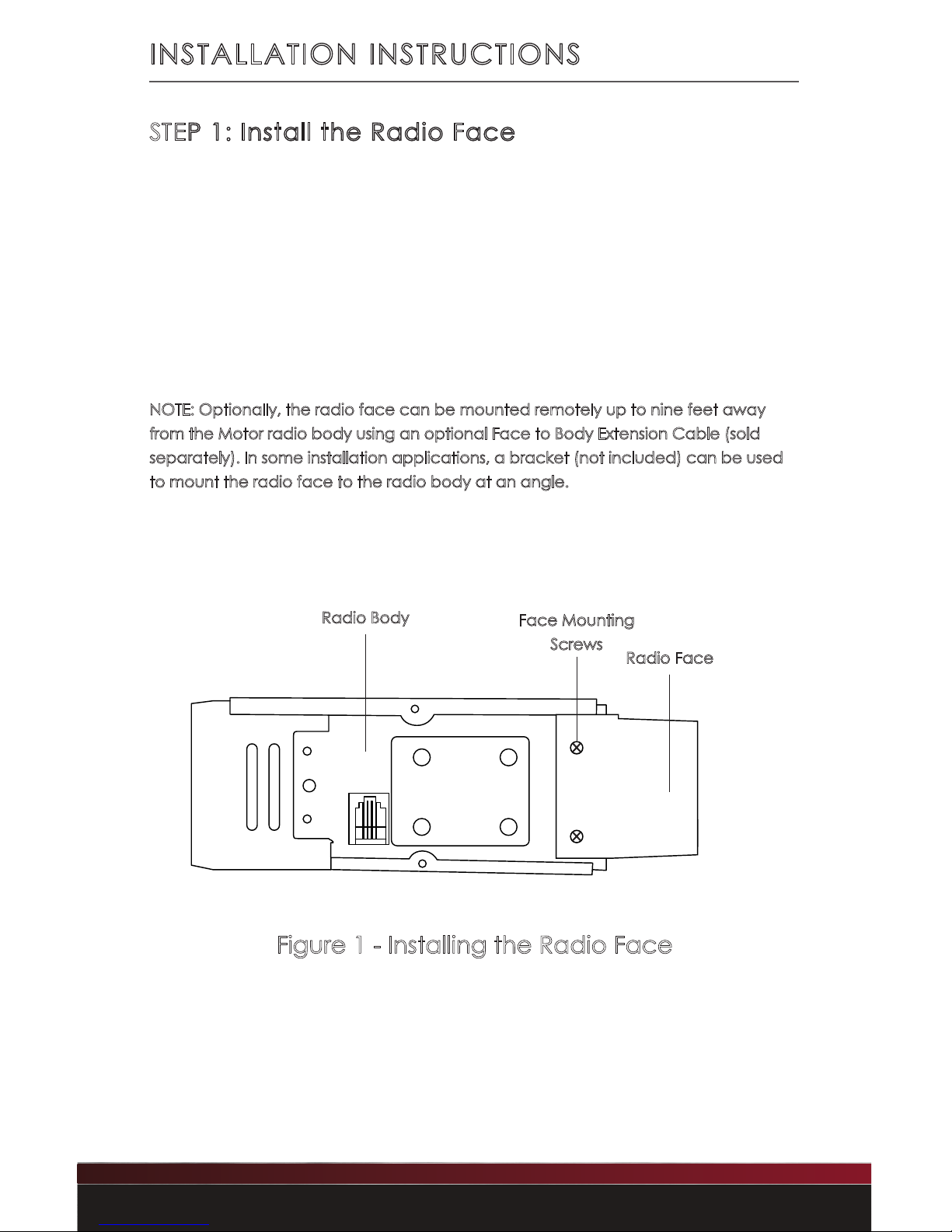
STEP 1: Install the Radio Face
Plug the ribbon cable (included with the Motor) into the front
of the Motor radio body and the back of the radio face. After
doing this, attach the radio face to the front of the radio body
using the four radio face mounting screws provided in the
radio face box.
The RetroSound® logo on the Motor radio body should be facing
upwards. Make sure to not install the face to the body upside down.
NOTE: Optionally, the radio face can be mounted remotely up to nine feet away
from the Motor radio body using an optional Face to Body Extension Cable (sold
separately). In some installation applications, a bracket (not included) can be used
to mount the radio face to the radio body at an angle.
INSTALLATION INSTRUCTIONS
Figure 1 - Installing the Radio Face
Radio Face
Radio Body
Face Mounting
Screws
Page 9
8
Copyright © 2019 Retro Manufacturing, LLC
INSTALLATION INSTRUCTIONS
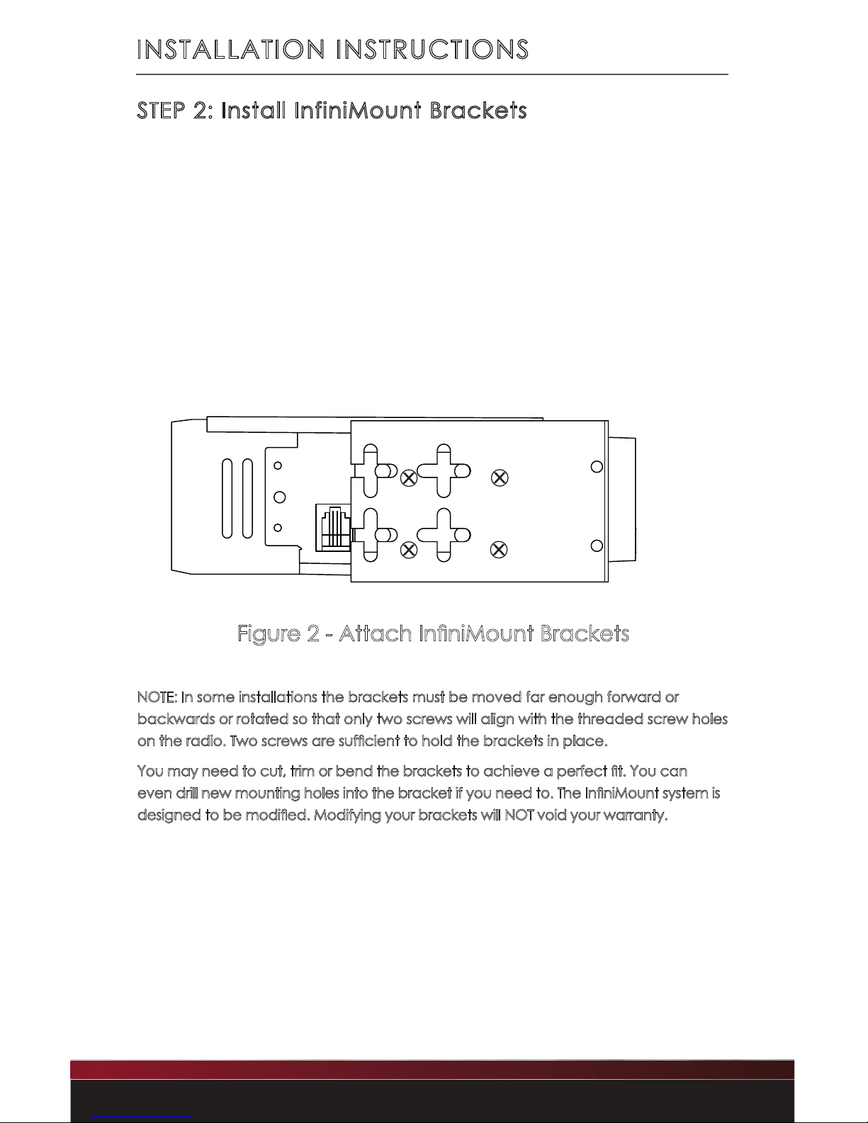
STEP 2: Install InfiniMount Brackets
Attach each InniMount bracket to the correct side of the radio
using the supplied screws. Before tightening the screws, you need
to adjust the brackets up, down, forward or backward. You may
also rotate, cut, or bend the brackets to achieve the perfect t
(See Figure 2). Complete the assembly with at least two screws
tightened on each side.
NOTE: In some installations the brackets must be moved far enough forward or
backwards or rotated so that only two screws will align with the threaded screw holes
on the radio. Two screws are sufcient to hold the brackets in place.
You may need to cut, trim or bend the brackets to achieve a perfect t. You can
even drill new mounting holes into the bracket if you need to. The InniMount system is
designed to be modied. Modifying your brackets will NOT void your warranty.
Figure 2 - Attach InniMount Brackets
R
Page 10
9
INSTALLATION INSTRUCTIONS
STEP 3: Mount Shafts to Brackets
To match the the location of your shafts to the proper width of your
vehicle’s dash, rst measure the distance between your existing shaft
holes from center to center.
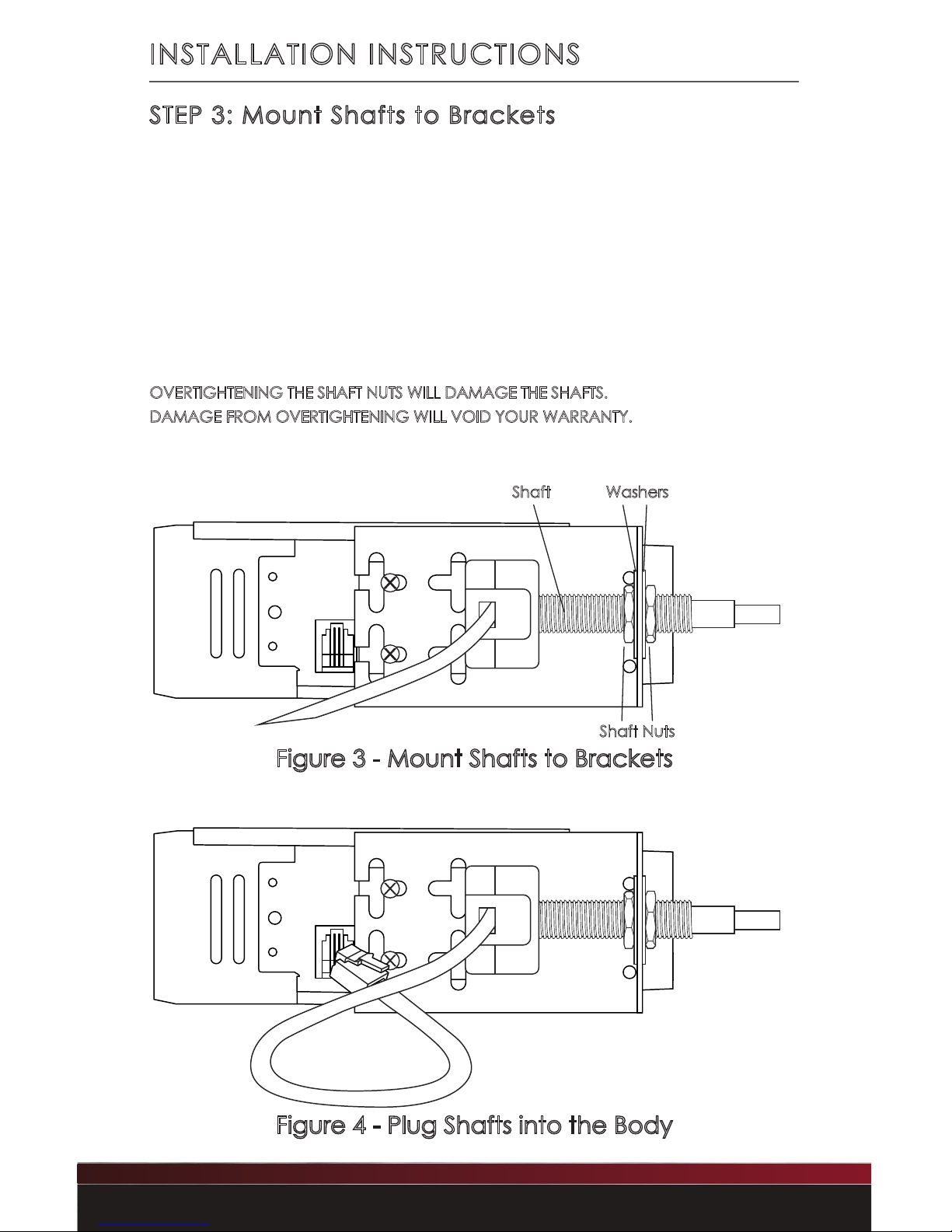
Mount a shaft to each bracket using the supplied shaft nuts
and washers. Finger tighten the shaft nuts to prepare for the nal
installation (See Figure 3). Once you ensure proper width, tighten
the screws and nuts (DO NOT OVERTIGHTEN).
OVERTIGHTENING THE SHAFT NUTS WILL DAMAGE THE SHAFTS.
DAMAGE FROM OVERTIGHTENING WILL VOID YOUR WARRANTY.
Finally, plug the shafts into each side of the body (See Figure 4).
Figure 3 - Mount Shafts to Brackets
Shaft Washers
Shaft Nuts
Figure 4 - Plug Shafts into the Body
Page 11
10
Copyright © 2019 Retro Manufacturing, LLC
INSTALLATION INSTRUCTIONS
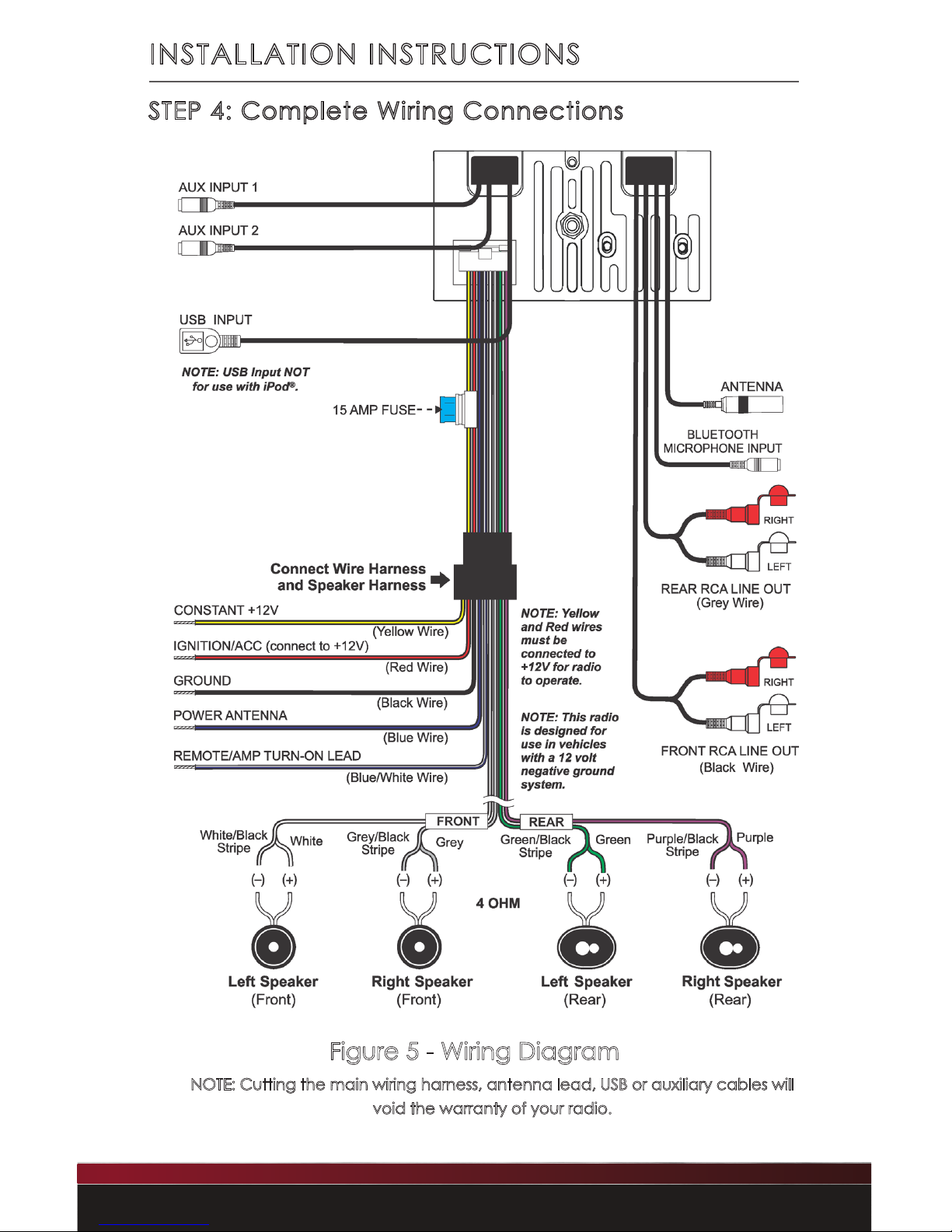
Figure 5 - Wiring Diagram
NOTE: Cutting the main wiring harness, antenna lead, USB or auxiliary cables will
void the warranty of your radio.
STEP 4: Complete Wiring Connections
Page 12
11
NOTE: This unit requires +12-volts to both the red and yellow wires to operate properly.
Locate the three wire harnesses: main wire harness, power wire
harness and speaker wire harness (See “What’s in the Box” on page
3). First connect the main wire harness to the back of the radio.
Then connect both the power and speaker wire harnesses to the
black female plug of the main wire harness.
After doing this, connect the bare wire ends of your power and
speaker wires to the appropriate power and speaker locations in your
vehicle (Refer to Figure 5 on the previous page). Have your radio
installed by a professional if this part of the install is too difcult, or
contact us if you have questions.
Installation Notes
• To prevent damage to the unit, do not connect the power
connector until you have completed the wiring process.
• This is a 12-volt negative ground ONLY radio. If you have a
positive ground, or a 6-volt system, you need to either convert
to 12-volts or purchase a separate inverter that would increase
the voltage to 12-volts.
• Please note that any inverter must be rated at 10 amps or
higher in order for the radio to operate properly.
Rear AUX and USB Inputs
Two AUX 3.5mm inputs are located at the rear of the Motor radio
body. These auxiliary inputs allow you to listen to any external source
with a standard headphone output. An example of an external
source would be a MP3 player, iPod® or iPhone®, portable CD player
or portable satellite radio receiver. To use this input, the auxiliary
cables must be routed to an accessible area during installation.
INSTALLATION INSTRUCTIONS
Page 13
12
Copyright © 2019 Retro Manufacturing, LLC
INSTALLATION INSTRUCTIONS
One USB connector cable is located at the rear of the Motor radio
body. During installation, you must route the cable to a convenient and
accessible location for plugging in USB devices.
If the cables provided are not long enough, you may use our optional USB/
AUX Extension Cable (USB PORT, not included) to extend the reach of the
cable. This cable also allows you to install the USB/AUX port into the factory
location for the cigarette lighter for a factory look and easy access.
Bluetooth Microphone
Plug in the Bluetooth® microphone and route it to an accessible area such
as the steering column or A-pillar.
Mount the Bluetooth® microphone
inside the vehicle close to the driver where the wires will not obstruct
the view or interfere with driving. The microphone is very sensitive,
and you may speak at normal volume when using hands-free
operation.
STEP 5: Finish the Installation
IF USING A BEZEL, Place the bezel on the face of the radio, then install the
assembled radio from behind the dash until the bezel and radio face are
ush with the front of the dash and the radio shafts protrude through the
shaft openings in the dash. Using the supplied washers and shaft nuts (see
“What’s In the Box” on page 3), secure the radio to the dash.
IF USING A FACEPLATE, slide the radio into the hole from behind the dash,
then align the faceplate over the radio shafts from the front. Using the
supplied washers and shaft nuts (see “What’s In the Box” on page 3),
secure the faceplate to the dash and the radio.
DAMAGE RESULTING FROM OVERTIGHTENING THE SHAFT NUTS
WILL VOID YOUR WARRANTY.
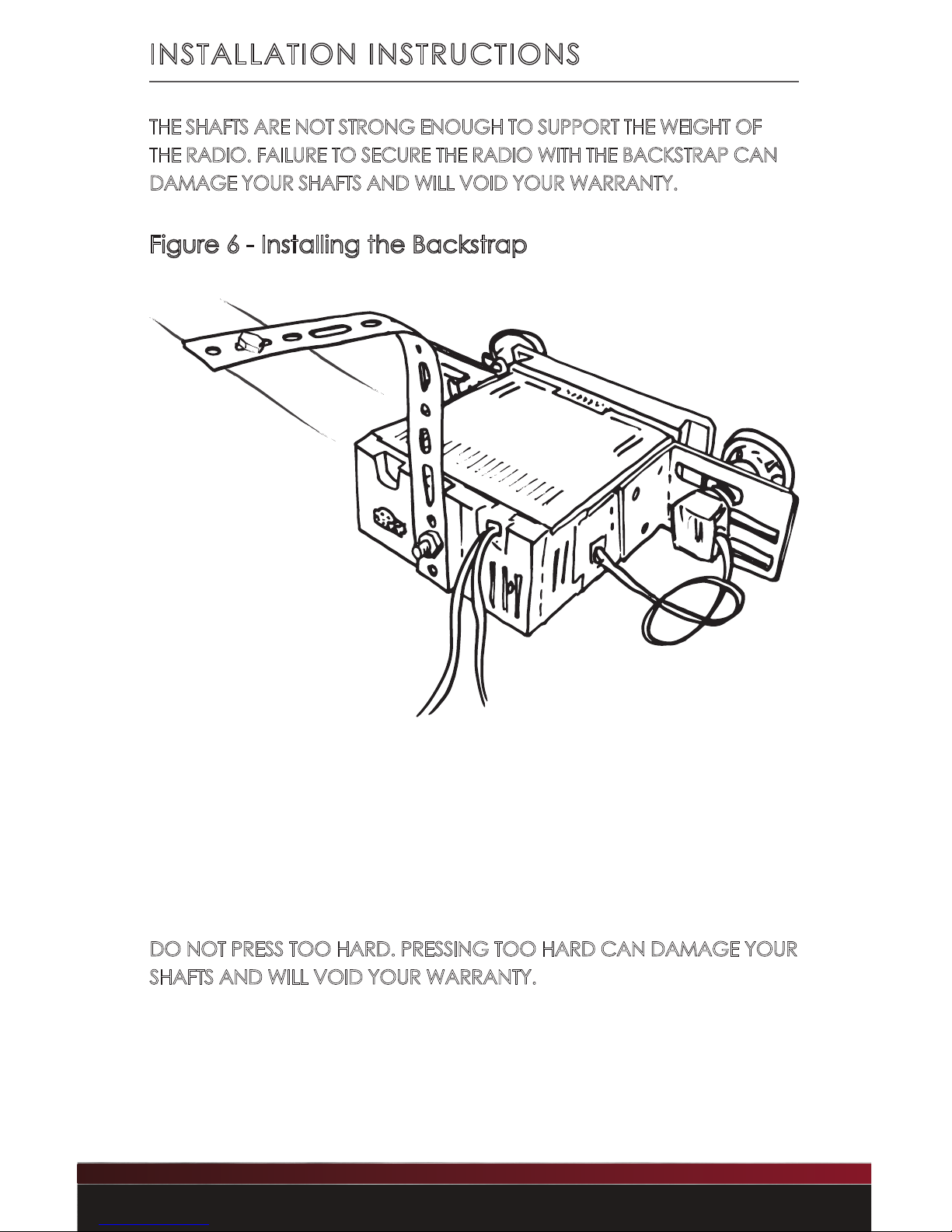
Next, you’ll need to secure the rear of the radio using the supplied
backstrap and hardware (see “What’s in the Box” on page 3). The
backstrap mounts using the threads in the rear of the radio body and
can be bent and adjusted to align with the mounting point of the original
factory radio behind the dash. (refer to Figure 6 on the next page)
Page 14
13
INSTALLATION INSTRUCTIONS
Figure 6 - Installing the Backstrap
View from behind dash
THE SHAFTS ARE NOT STRONG ENOUGH TO SUPPORT THE WEIGHT OF
THE RADIO. FAILURE TO SECURE THE RADIO WITH THE BACKSTRAP CAN
DAMAGE YOUR SHAFTS AND WILL VOID YOUR WARRANTY.
Finally, slide the rear knobs over the shafts, rotating them into the
correct position, and push them into place. Mount the front knobs by
gently pressing them onto the shaft.
DO NOT PRESS TOO HARD. PRESSING TOO HARD CAN DAMAGE YOUR
SHAFTS AND WILL VOID YOUR WARRANTY.
Page 15
14
Copyright © 2019 Retro Manufacturing, LLC
OPERATING YOUR RADIO
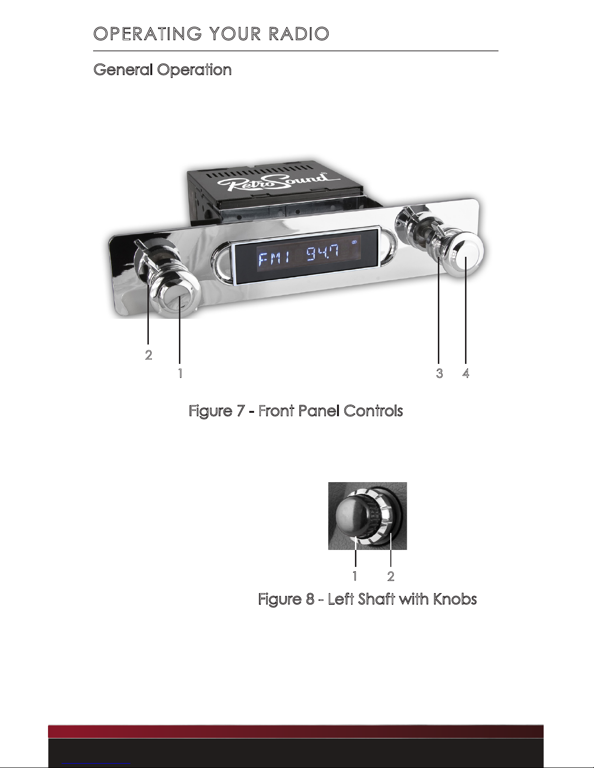
General Operation
Figure 7 - Front Panel Controls
Figure 8 - Left Shaft with Knobs
1
2
3 4
1. Left-front Knob
2. Left-rear Knob
3. Right-rear Knob
4. Right-front Knob
1
2
Page 16
15
OPERATING YOUR RADIO
General Operation
Power On/Off
Press the left-front knob (#1) to turn the unit on. RETROSOUND will
appear on the screen.
Press and hold the left-front knob (#1) to turn the unit off.
GOODBYE will appear on the screen to conrm that it has turned off.
Volume
Turn the left-front knob (#1) to adjust the volume between 0-46.
Source Mode
Turn the left-rear knob (#2) clockwise to select from available
listening sources: RADIO, AUX 1, AUX 2, USB, BT-Audio.
(The USB source modes will not appear unless a USB device is
plugged in).
The auxiliary and USB inputs are located at the back of the radio
body. The auxiliary inputs may be used to play music from any
portable device with a standard 3.5mm headphone output, such
as a MP3 player, iPod® or iPhone®, portable CD player or portable
satellite radio receiver. The USB inputs allow you to play music from
a ash drive. To use these inputs, the cables must be routed to an
accessible area during installation.
Radio Tuning
Turn the right-front knob (#4) to tune to the next or previous
AM/FM frequency.
NOTE: When the radio is tuned to a strong stereo FM station, the stereo indicator will
appear on the upper right corner of the LCD screen (two oval circles).
Page 17
16
Copyright © 2019 Retro Manufacturing, LLC
OPERATING YOUR RADIO
Radio Bands
Turn the right-rear knob (#3) counter-clockwise to toggle through
ve independent radio bands (two AM and three FM).
Storing Radio Pre-sets
There are six radio pre-sets for each radio band. To toggle through
pre-sets 01 to 06 rotate right-rear knob (#3) clockwise. To store a preset: Using right-front knob (#4) tune to desired station then toggle
right-rear knob (#3) to the desired pre-set location (1-6) once preset location is selected press right-front knob (#4) to store.
Selecting Radio Pre-sets
To recall radio pre-sets, turn the right-rear knob (#3) clockwise and
release it. Repeat to move through the pre-sets.
Mute
Press the right-front knob (#4) to mute or unmute.
Page 18
17
OPERATING YOUR RADIO
TONE CONTROLS
This sub-menu allows advanced tonal adjustments, balance and
fader controls and the preset equalizer options. To access this sub-
menu, press the left-front knob (#1). Keep pressing the left-front knob
to scroll through the available options. To adjust within the sub-menu,
turn the left-front knob clockwise or counter-clockwise.
Digital Signal Processor (DSP)
This sub-menu toggles the Digital Signal Processor (DSP) on and off.
Factory default is DSP OFF. Activiating DSP allows you to choose one of
three preset equalization settings:
• CLASSIC This setting offers subtle sonic adjustments
that lend themselves to classical music.
• POP This setting accentuates bass and treble
frequencies and is suitable for popular music.
• ROCK This setting accentuates treble frequencies
and is suitable for rock music.
Bass
This sub-menu (bass) allows bass tone adjustments.
You may boost or cut low frequencies from +7 to -7.
Middle
This sub-menu (MIDDLE) allows mid tone adjustments.
You may boost or cut mid frequencies from +7 to -7.
Treble
This sub-menu (treble) allows treble tone adjustments.
You may boost or cut high frequencies from +7 to -7.
Page 19
18
Copyright © 2019 Retro Manufacturing, LLC
OPERATING YOUR RADIO
Balance
This sub-menu (bal) allows adjustment of stereo sound to left or right.
This may be helpful in compensating for the position of the driver
in relation to the vehicle’s speakers. Adjustment range is from 0-12
between left and right speakers.
Fader
This sub-menu (fader) allows you to adjust the sound between the
front and rear speakers. Adjustment range is from 0-12 between front
and rear speakers.
XBAS
This sub-menu (XBAS) boosts bass and treble for listening at low
volumes. This should only be used at low volume levels and should be
set to XBAS OFF at higher volumes.
Bass Crossover Frequency
This sub-menu (BAS 80H) adjusts the frequency crossover of the bass-
tones between 60Hz, 80Hz, 100Hz or 200Hz.
Middle Crossover Frequency
This sub-menu (MID 1.0K) adjusts the frequency crossover of the mid-
tones between 0.5KHz, 1.0KHz, 1.5KHz or 2.5KHz.
Treble Crossover Frequency
This sub-menu (TRE 10.0K) adjusts the frequency crossover of the treble-
tones between 10.0KHz, 12.5KHz, 15.0KHz or 17.5KHz.
SYSTEM SETTINGS
The System Settings sub-menu system enables access to numerous
additional features of your radio. Press and hold the right-front knob
(#4) for three seconds to access the System Settings sub-menu.
Then rotate the right-front knob (#4) clockwise to scroll through the
available sub-menu options. In a specic sub-menu, press the rightfront knob (#4) to change the options.
Page 20
19
OPERATING YOUR RADIO
Auto Seek/Manual
This sub-menu allows you to select either Auto Seek or Manual tuning
when listening to the radio. In Auto Seek mode, the radio will tune to
the next available station when tuning. Press the right-front knob (#4)
to change this function.
A Store
This sub-menu will automatically ll FM pre-sets on all three FM bands
of six pre-sets each (eighteen total pre-sets) with the strongest
stations. To activate this feature, once in the system settings, rotate
the right-front knob (#4) clockwise until A Store appears on the
screen, then press the right-front knob (#4) to activate. This process
can take up to one minute.
Local/Distant
Using the right-front knob (#4), this sub-menu changes the sensitivity
of the FM tuner. When listening to the FM tuner, selecting between
LOCAL and DISTANT can aid in listening to weak FM stations or
compensate for stations that have too strong a signal.
Clock
This sub-menu allows you to set the clock. To adjust hours, rotate right-
front knob (#4) clockwise until CLK appears. Press right-front knob (#4)
to adjust hours. Adjusting past 12 will toggle the AM/PM indicators.
Once the hour is set, press the right-front knob (#4) to adjust minutes.
Once minutes are set, press the right-front knob (#4) to access the
12/24 menu.
Clock 12/24
Using the right-front knob (#4), this sub-menu allows you to adjust
the clock from a twelve hour clock to a twenty-four hour clock. The
factory default setting is for a twelve hour clock (CLK 12).
Page 21
20
Copyright © 2019 Retro Manufacturing, LLC
OPERATING YOUR RADIO
Display Frequency/Clock
Using the right-front knob (#4), this sub-menu allows you to adjust the
priority screen view between radio frequency (DISP FREQ) and clock
(CLK).
Clock ON/OFF
Using the right-front knob (#4), this sub-menu allows you to turn off
the clock when the radio is off. Default is CLK ON.
Beep On/Off
Using the right-front knob (#4), this sub-menu controls the audible
beep conrmation that sounds during operation of the radio. Select
BEEP ON to hear the audible beep, and BEEP OFF to disable the audible
beep.
Display Color (SCAN)
This sub-menu changes the display color. The default setting is SCAN,
which will scan through all of the available colors. To customize your
display color, look for the word SCAN in the sub-menu (if a custom
color has already been chosen, look for that color name in the sub-
menu), then press the right-front knob (#4) to select one of the pre-set
colors: white, green 1, green 2, green 3, orange, red, pink, purple 1,
purple 2, blue 1, blue 2, user, Scan.
To create a custom color, select USER in the pre-set color menu, then
rotate the right-front knob (#4) once. The display will say RGB. Now
press the right-front knob (#4) once. This will allow you to edit the RGB
values for 32,000 color variations. Rotate the right-front knob (#4) to
adjust the reds, then press the same knob (#4) to move to the greens.
Repeat this process to adjust the greens and the blues.
NOTE: If you lower all RGB settings down to “00” the display will go black, and you will
need to reset the radio by disconnecting all power from the unit for 2 minutes.
Page 22
21
OPERATING YOUR RADIO
Dimmer High/Low
Using right-front knob (#4), this sub-menu allows you to adjust the
radio’s display brightness between high (DIMM HIGH) and low (DIMM LOW).
Bluetooth® ON/OFF (BT)
Using right-front knob (#4), this sub-menu turns Bluetooth® on or off.
Bluetooth® must be enabled in order to connect a Bluetooth® device
for hands-free operation or streaming audio.
Bluetooth® Connect/Disconnect
Using right-front knob (#4), this sub-menu allows the radio to be
discoverable on your Bluetooth® device. Choose BT CONNEC to
allow your device to connect, and BT DISCON to disable Bluetooth®
connections.
To connect your device, choose BT CONNEC, then search for
“RETROSOUND” in your phone’s Bluetooth® device list.
Enter password “0000” if prompted.
Area USA/EUR/AUS/JAP/RUS
Apache has the capability to receive radio broadcasts from around
the world. This sub-menu allows you to adjust to broadcasts in your
country. Factory default setting is United States (USA). Turn the right-
front knob (#4) to toggle between Europe (EUR), Australia (AUS), Japan
(JAP) and Russia (RUS). To conrm the change, pause to let the sub-
menu revert to your tuner. You will see your selected tuner mode: AREA
USA, AREA EUR, AREA AUS, AREA JAP, AREA RUS.
Volume Last/Adjust
Using right-front knob (#4), this sub-menu allows you to adjust the
volume level that the radio rst turns on to. The factory default setting
is VOL LAST, which sets the turn on volume at the last volume used. VOL
ADJUST allows you to pre-set the volume level between 0-46 upon
radio activation.
Page 23
22
Copyright © 2019 Retro Manufacturing, LLC
USB DEVICE INSTRUCTIONS
Connecting a USB Device
The USB input is located at the rear of the radio body. The USB
cable must be routed to a convenient and accessible location for
plugging in USB devices.
Once you have turned on your radio and connected your ash
drive or supported USB device to the USB input, the radio will nd
your songs and automatically begin playing them.
The icon appears on the LCD during USB playback.
To change songs, rotate the right-front knob (#4) to access the
next or previous song. To cycle through folders, turn the right-rear
knob (#3) clockwise, then rotate the right-front knob (#4) to cycle
through the folders. To play/pause, listen to 10 seconds of each
song (INT), repeat the track you’re listening to (RPT) or randomly
select from all songs on the attached ash drive or supported USB
device (RDM), press the left-front knob (#1) to access the USB menu.
About MP3/WMA/FLAC
MP3 (MPEG Audio Layer-3) and WMA (Windows Media Audio)are
for compressed audio les. When your radio is in USB mode, you can
play MP3 and unprotected (no DRM) WMA les off the ash drive.
Common facts about these compressed-sound formats:
• High bit rate and high sampling frequencies are
recommended for high sound quality.
• Selecting VBR (Variable Bit Rate) is not recommended
because playing time is not displayed properly and there
may be some audible skipping artifacts. The playback sound
quality differs depending on the encoding circumstances. For
details, refer to the user manual of your encoding software.
Page 24
23
USB DEVICE INSTRUCTIONS
• When adding MP3 les to your ash drive, it is recommended
to set the bit rate to 128 kbps or more and “xed.”
• When adding WMA les to your ash drive, it is
recommended to set the bit rate to 64 kbps or more
and “xed.” Do not set the copy protect attribute on the
WMA le or you will not be able to play the track.
• Apache will read only FAT32 formatted ash drives.
This radio will NOT read NTFS formatted drives.
• Apache will read les placed in the root directory rst before
playing les in the folder structure of the drive. Please note
that les are read in order of creation NOT alphabetically
or numerically. Older les will get read rst in a folder.
Viewing MP3/WMA Song Information
When playing MP3/WMA les from the USB source, you can view the
track name, album, artist (ID-3) information automatically from these
les. Once the USB drive is inserted, the following information will
scroll across the screen in the following order: F-DIR (folder directory),
MP3 FILE (le name of song), ALBUM (name of album) ARTIST (name of
artist), SONG (name of song).
To access the clock when in USB mode, turn the left-rear knob (#2)
counter-clockwise. The clock will time out after a few seconds and will
revert to the ID-3 information. Turning the left-rear knob (#2) counter-
clockwise again will revert to viewing the ID-3 information on-screen.
NOTE: FLAC format does not support ID-3 information and will not display the artist or
song information. Not all music software handles ID-3 information the same way. Some
software will produce MP3 les with ID-3 information that is not readable by the radio
Motor. If this occurs, you may need to use a converter or ID-3 editor to change the ID-3
information for the artist, album and song information to display properly on your radio.
Page 25
24
Copyright © 2019 Retro Manufacturing, LLC
BLUETOOTH® DEVICE INSTRUCTIONS
Bluetooth® Instructions
Bluetooth® Hands-Free and A2DP Streaming Operation
You can make or receive phone calls using a Bluetooth® enabled
phone connected to your radio and control basic functions via
the radio interface. During a call, the radio music source will
be muted and the call will broadcast through your car speaker
system. You can also listen to music stored on a A2DP enabled
Bluetooth® device.
Pairing a Bluetooth® Device
When connecting a Bluetooth® device for the rst time, you must
rst pair the device with the unit. For most devices, pairing only
needs to be done once.
1. To pair your device, rst make sure the Bluetooth® function
is turned on in the radio sub-menu.
2. Then, change the BT DISCON function to BT CONNECT to make
your radio discoverable (ensure Bluetooth® is enabled on
your device).
3. Next, search for a new Bluetooth® device from the phone
(this may take up to 30 seconds) and select “RETROSOUND”
from the Bluetooth® device list.
4. If prompted, enter “0000” for the PIN. If successful, “PAIRING OK”
will be displayed on the LCD screen.
The paired device will then connect to your radio automatically.
On some devices, you may need to select “SET AS AUTHORIZED” or
similar to ensure your radio will automatically pair on future usage.
PAIRED NOTIFICATION DISPLAY: When the Bluetooth® device is
paired with your radio, the Bluetooth® icon will appear on the
LCD screen. This will occur whenever you use the system while the
paired device is within range.
Page 26
25
BLUETOOTH® DEVICE INSTRUCTIONS
Placing a Call
1. Dial the desired number on the paired phone.
2. Once dialing is in progress, CALLING will appear on the screen.
3. Once the call is in progress, TALK will appear on the
screen along with the elapsed call time (TALK 00:00).
Receiving a Call
1. If a call is incoming, any audio playback from the current
source will either be muted or paused (depending on the
source) and PHONE IN will be shown on the screen along
with the caller ID if it is enabled by the phone/carrier.
2. To accept the call, turn the left-rear knob (#2)
counter-clockwise.
Ending a Call
To end the call, turn the left-rear-knob (#2) counter-clockwise.
Streaming Music From Your Device
1. Once your device is paired with your radio, make sure the
source mode is set to BT AUDIO.
2. Next, select your desired playback source on your device
(iTunes®, Pandora®, etc) and play the music as you normally
would.
Page 27
26
Copyright © 2019 Retro Manufacturing, LLC
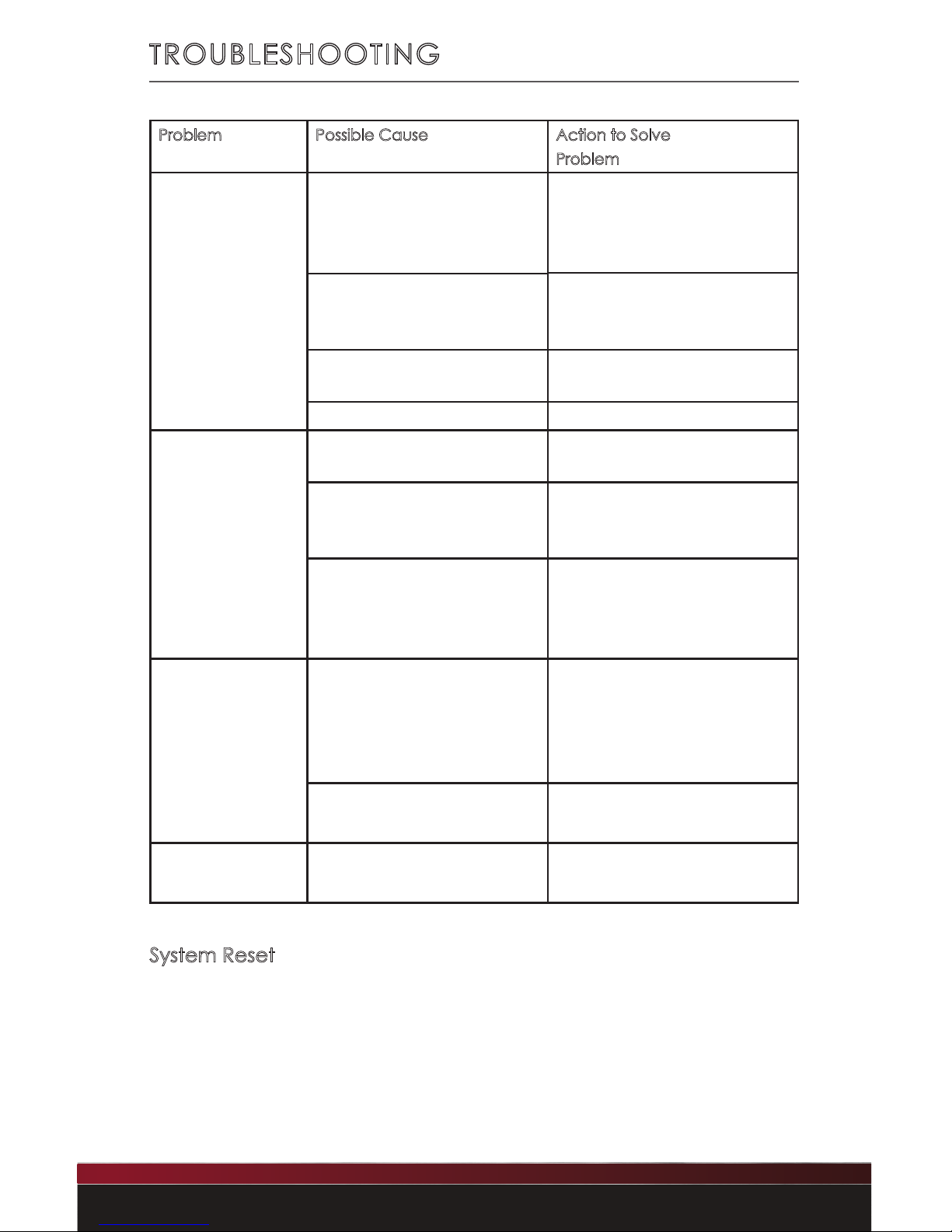
TROUBLESHOOTING
Problem Possible Cause Action to Solve
Problem
Radio will not turn
on (no lights,
no sound)
Yellow Constant +12-volt wire
not connected or incorrect
voltage.
Check all connections for
proper voltage with a volt
meter. Voltage range:
12-15-volts
Check +12-volt
accessory wire
connection
Red Ignition/Acc wire not
connected or incorrect
voltage.
Ground wire
not connected
Check ground
connection
Fuse on Batt+ is blown Replace blown fuse
No sound heard
from unit but unit
lights up
Volume turned
all the way down
Increase radio volume
Internal amp in
protection mode
Check speaker leads
for any grounded or
shorted wires
Wrong source mode selected Make sure the unit is in the
desired source mode
(RADIO, AUX 1, AUX 2, USB, BT-
Audio)
Unit blows fuses Possible short in wiring Incorrect fuse used, make sure
only fuses with correct 15 amp
ratings are used and check all
wiring connections for
possible short
Battery hooked up
backwards
Make sure battery is properly
connected
USB Error Invalid media / device type Ensure le formats and devices
are acceptable for playback
System Reset
To restore/reset the unit to factory defaults, remove all power from
the unit, wait 5 minutes and then reconnect power.
Page 28
27
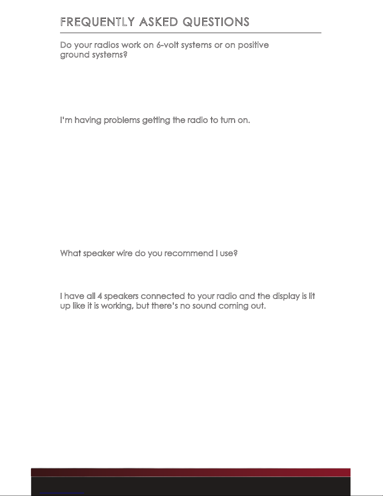
Do your radios work on 6-volt systems or on positive
ground systems?
No. Our radios are 12-volt, negative ground only. After-market
converters and inverters are available but must have at least 10
amps of continuous output.
I’m having problems getting the radio to turn on.
RetroSound® radios require 12-volts to both power leads. The red
lead (+12-volt accessory) goes to a switched power source, and
the yellow to a constant +12-volt power source. Using a volt meter,
check the voltage when the key is turned from “off” to “on”. If
there is a signicant drop in the voltage, the circuit that the yellow
lead is attached to cannot handle the additional draw of the
radio. You will need to nd another circuit that can handle the
additional draw of the radio, or you will need to go directly to the
battery.
What speaker wire do you recommend I use?
We recommend using 16-gauge wire for the speakers.
I have all 4 speakers connected to your radio and the display is lit
up like it is working, but there’s no sound coming out.
This usually indicates one of two things:
• Speaker wires are touching each other or the vehicle chassis at
some point. Check each speaker lead from radio to speaker.
• Speaker impedance is below 4 ohms. Older speakers are
usually not compatible with modern electronics.
FREQUENTLY ASKED QUESTIONS
Page 29
28
Copyright © 2019 Retro Manufacturing, LLC
FREQUENTLY ASKED QUESTIONS
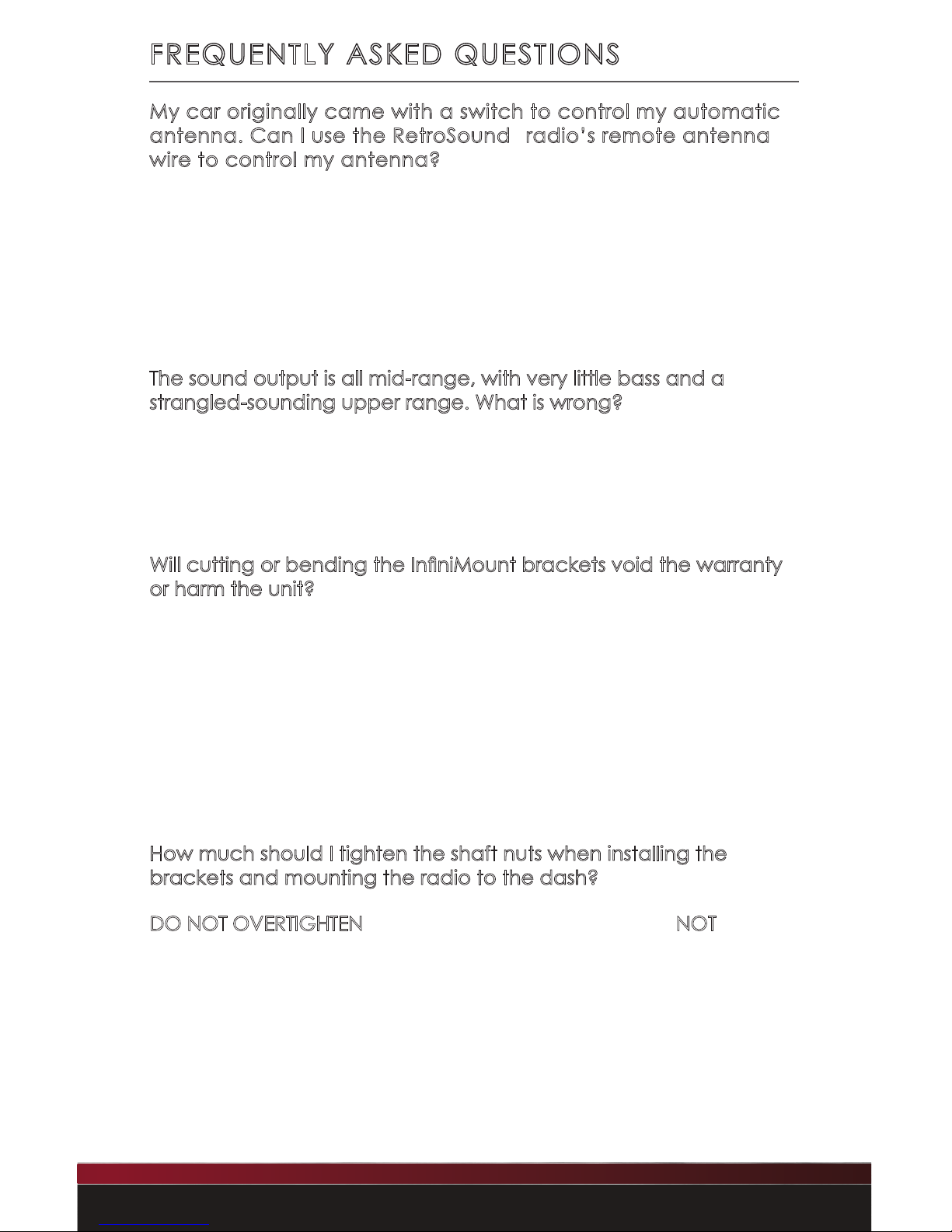
My car originally came with a switch to control my automatic
antenna. Can I use the RetroSound® radio’s remote antenna
wire to control my antenna?
No you cannot. Your factory antenna is known as “semiautomatic.” It requires a switch to either extend or retract the
antenna. You must retain this switch to control your antenna; the
RetroSound® radio’s power antenna wire is for more modern “fullyautomatic” antennas not requiring a separate switch.
The sound output is all mid-range, with very little bass and a
strangled-sounding upper range. What is wrong?
One of your speaker wires is connected backwards. This is called
being “out of phase.” Check to make sure positive is wired to
positive and negative to negative on all your speakers.
Will cutting or bending the InniMount brackets void the warranty
or harm the unit?
No. The RetroSound® patented InniMount bracket system has
been designed specically to be bent, cut and modied to simplify
radio installation. Modication to the radio’s brackets is actually
encouraged to ensure proper t.
If you have questions about modifying the bracket system, please
contact us.
How much should I tighten the shaft nuts when installing the
brackets and mounting the radio to the dash?
DO NOT OVERTIGHTEN the shaft nuts. The shaft nuts are NOT the
only means of securing the radio to the dash. There is a backstrap
included which works with the shaft nuts to secure the radio to the
dash. Please note that overtightening the shaft nuts could break the
shafts. Retro Manufacturing, LLC will not be responsible for broken
shafts due to overtightening of the shaft nuts.
Page 30
29
FREQUENTLY ASKED QUESTIONS
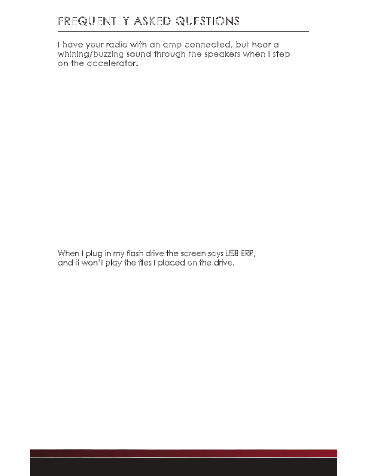
I have your radio with an amp connected, but hear a
whining/buzzing sound through the speakers when I step
on the accelerator.
If you have an external amplier installed and experience a high-
pitched noise that varies with the engine’s RPM, there are many
possible solutions:
• Make sure the amplier’s gain controls are not turned all
the way up. Ampliers amplify everything, including noise.
• Try grounding the amplier near where it is installed.
• Try a lter on the amplier’s 12-volt power lead. Make sure
to use a lter that includes a ground wire.
• On rare occasions, noise can be introduced through the
antenna lead. If disconnecting the antenna makes the noise
go away, you need to replace or repair the antenna plug
where it goes into the radio.
When I plug in my ash drive the screen says USB ERR,
and it won’t play the les I placed on the drive.
• Make sure the les on the drive are .mp3 or unprotected .wma
(Windows Media Audio) les. iTunes® les are .m4a format
and need to be converted to .mp3 format, which can easily
be done using iTunes®.
• Verify the capacity of the ash drive. Apache will only play
1 gig up to 32 gig size ash drives.
• Make sure the ash drive is not NTFS formatted. Always use the
FAT32 format (most drives are formatted with FAT32 from the
factory). Be sure to do a full format rather than a quick format,
and check that none of the les or folders have names
longer than 64 characters. It is very important that none of the
audio les have DRM. Use only MP3 les or unprotected
Windows Media format les.
Page 31
30
Copyright © 2019 Retro Manufacturing, LLC
SPECIFICATIONS
FM
Tuning Range (USA, EUR, AUS, JAP, RUS tuning capable) 87.5-107.9MHz
Antenna Terminal External Antenna Connector
Usable Sensitivity 12.5 dBf
Selectivity 75 dB @ 400kHz
Signal to Noise Ratio 62 dB (Stereo), 67 dB (mono)
Harmonic Distortion @ 1 kHz 0.8% (stereo), 0.5% (mono)
Separation 32 dB @ 1kHz
Frequency Response 30-16,000 Hz
AM
Tuning Range (USA, EUR, AUS, JAP, RUS tuning capable) 530-1710 kHz
Antenna Terminal External Antenna Connector
General
Dimensions (radio face) 3.75”W x 1” H x 1.05” D
Dimensions (radio body) 3.96”W x 1.98”H x 4.30”D
Power Requirements 10.5-14.4-volts
Current Consumption (during operation) Max. 15A
Current Consumption (car off) <3.5 mA
Output Power (@ 14.4-volts @ 4 ohm @ 1% THD) 25x4 watts RMS/45x4 watts Peak Power
Output Impedance 4-8ohm
Low Level Output (4 channels) 2.85-volts
AUX 1 Input (AUX cable length, 8”) >300 mV / 6 kΩ
AUX 2 Input (AUX cable length, 8”) >300 mV / 6 kΩ
USB 1 Input (USB cable length, 20”) 5V (USB female input)
NOTE: All specications are subject to change without notice.
Page 32
31
Limited Warranty
If your unit does not work properly because of defects in materials and workmanship, Retro
Manufacturing, LLC (collectively referred to as “the warranter”) will for the length of the period
indicated in the chart below at its option either (a) repair your unit with new or refurbished parts,
or (b) replace it with a new or refurbished unit. The warranty period starts with the date of original
purchase. The decision to repair or replace will be made by the warranter.
CATEGORIES Warranty
Apache RetroRadio
TM
One (1) Year
During the warranty period, there will be no charge for replacement parts. You must mail in your
unit prepaid during the warranty period. This warranty only applies to products purchased and
serviced in the United States. This warranty is extended only to the original purchaser of a new
product which was not sold “as is.” A purchase receipt or other proof of the original purchase
date is required for warranty service.
To handle a warranty issue, contact us at [email protected] or 888.325.1555 for a
Return Authorization (RA) number. All returns and warranty issues must be accompanied by a
Return Authorization number. Any product received without a RA number will be refused. If a
radio is returned for credit any missing parts will be debited from the retrun price.
LIMITED WARRANTY-LIMITS AND EXCLUSIONS
This warranty ONLY COVERS failures due to defects in materials and workmanship; warranty DOES
NOT COVER normal wear and tear or cosmetic damage. The warranty ALSO DOES NOT COVER
damages which occurred during shipment, failures which are caused by products not supplied
by the warranter, failures which result from accident, misuse, abuse, neglect, bug infestation,
mishandling, misapplication, alteration, faulty installation, set-up adjustment, maladjustment of
consumer control, improper maintenance, improper antenna, inadequate signal reception or
pickup, power line surge, improper voltage supply, lightning, modication, commercial use (such
as use in hotels, ofces, restaurants, or other business uses) or rental use of the product, or service
by anyone other than Retro Manufacturing, LLC, or damage that is attributable to acts of God.
THERE ARE NO EXPRESS WARRANTIES EXCEPT AS LISTED UNDER “LIMITED WARRANTY”. THE
WARRANTER IS NOT LIABLE FOR INCIDENTAL OR CONSEQUENTIAL DAMAGES RESULTING FROM
THE USE OF THIS UNIT, OR ARISING OUT OF ANY BREACH OF THIS WARRANTY. (As examples,
this excludes damages for lost time, cost of having someone remove or re-install an installed
unit if applicable, travel to and from the servicer, and loss of media, data or other memory
contents. The items listed are not exclusive, but are for illustration only.) ALL EXPRESS AND IMPLIED
WARRANTIES, INCLUDING THE WARRANTY OF MERCHANTABILITY, ARE LIMITED TO THE PERIOD OF
THE LIMITED WARRANTY.
Some states do not allow the exclusion or limitation of incidental or consequential damages, or
limitations on how long an implied warranty lasts, so the exclusions may not apply to you. This
warranty gives you specic legal rights and you may also have other rights which vary from state
to state. If a problem with this unit develops during or after the warranty period you may contact
your dealer or Retro Manufacturing, LLC.
LIMITED WARRANTY
Page 33
32
Copyright © 2019 Retro Manufacturing, LLC
REPLACEMENT PARTS
If you need replacement parts, contact us at
[email protected] or call 888.325.1555
(See “What’s in the Box” on page 3 to conrm the part(s) needed).
Replaceable Items
• Main Wiring Harness*
• Power Wiring Harness*
• Speaker Wiring Harness*
• Metal Backstrap
• Metal Hardware Pack
• Plastic Washer Kit
• Shaft(s)
• InniMount Brackets (pair)
• Bezel / Faceplate
• Knobs
• Bluetooth Microphone
* These harnesses combine to make one complete part. They are not available separately.
Purchase Notes
Record the place and date of purchase for future reference.
Model No.
Serial No.
Purchase Date
Purchased From
Keep this information and your sales receipt in a safe place.
Page 34
33
INSTALLATION NOTES
Page 35
34
Copyright © 2019 Retro Manufacturing, LLC
INSTALLATION NOTES
Page 36

MODERN SOUND FOR YOUR CLASSIC
Retro Manufacturing, LLC, 7470 Commercial Way, Henderson, NV 89011
p) 888.325.1555 | f) 702.483.2229 | www.retromanufacturing.com
 Loading...