

Page 1
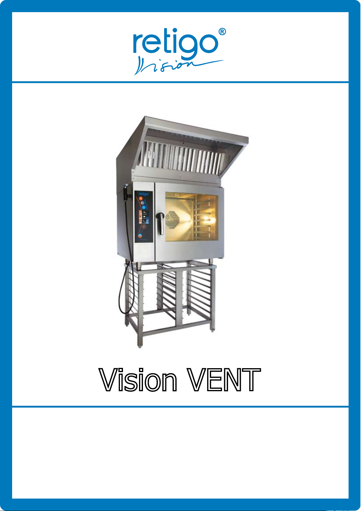
Vision VENT
Technical documentation
RETIGO 2011
Page 2

Page 3

CONTENT
INTRODUCTION
INTRODUCTION..........................................................................................................................2
1. Contact ......................................................................................................................................2
2. Use and description of the hood function .....................................................................................2
3. Improper use of this appliance ....................................................................................................2
4. Important notices .......................................................................................................................2
5. How to use this Manual .............................................................................................................. 3
6. Binding regulations ....................................................................................................................3
7. Limited.......................................................................................................................................3
SAFETY INSTRUCTION................ ..............................................................................................5
1. General safety data .....................................................................................................................5
2. Operating personnel designation..................................................................................................5
3. Perfect condition ........................................................................................................................5
4. Safety rules for work with the RETIGO Company products ............................................................. 5
TECHNICAL DATA................. ......................................................................................................6
TRANSPORT AND INSTALLATION..............................................................................................7
1. Appliance transportation .............................................................................................................7
2. Waste disposal ...........................................................................................................................7
3. The Appliance installation ...........................................................................................................7
4. Eletrical connections of the air condensation hood ........................................................................8
5. The hood set-up and control .....................................................................................................10
MAINTANCE AND CLEANING................ .................................................................................. 12
1
Page 4

INTRODUCTION
2
I N T R O D U C T I O N
The RETIGO Company is very grateful to you for your
decision to use our equipment. Your newly acquired
appliance represents rare fusion of long-term experien-
ce of our best chefs, latest scientic developments and
advantages of modern technology. To make sure you
will be happy with the performance of our appliance from
the very beginning, we would like to offer additional information and some advice for problem – free operation.
The RETIGO Company guarantees perfect functioning and high quality service. Therefore we are
offering:
• The Warranty guarantees 12 months of trouble-
free operation of the appliance. If you meet the sales
conditions, Warranty extends to 24 months; please
see the current price list.
• Spare parts delivered quickly on demand
• Technical and consulting service tied to service and
maintenance
• Professional consulting service by our professional
chefs
We wish you a lot of satisfaction working with the
RETIGO appliances and a lot of happy customers.
1. Contact
Should you have any questions, we are available
at the following phone numbers and addresses:
2. Use and description of the hood
The RETIGO hoods are designed for extraction and
condensation of vapors emanating from the Vision models of the RETIGO combi steamers. They are controlled by the combi steamer’s electronics.
After the combi steamer door is shut and prepa-
ration of food is triggered, the temperature inside the
cooking chamber is carefully monitored. If this temperature exceeds the temperature necessary for the hood
activation, extracting will be triggered at the lowest
level. If – during or after food preparation – the combi
steamer’s door opens, the appliance will automatically
switch to a higher level of vapor extraction in order to
achieve higher vapor suction. After the door is shut
again, the output of the hood will decrease back to
its original level. The hood will be completely turned
off once the cooking chamber temperature drops back
below the activation level.
This hood holds relevant EU Certicate of Confor-
mity.
3. Improper use of this appliance
Other than the above specied use of the appliance
shall be considered irregular and harmful.
The RETIGO Company bears no responsibility for any
damages, which may result from such action. In such
a case, all the risk is carried solely by the user!
Address:
Retigo, s.r.o.
Láň 2310, PB 43
CZ 756 64 Rožnov pod Radhoštěm
Tel./Fax: +420 571 652 434
Our professional salespeople are ready to help
you at this telephone Hot-line:
+420 603 571 360, +420 604 568 562
Our professional cooks are ready to help you at
this telephone Hot-line:
+420 603 854 372, +420 603 308 461
Our professional service technicians are ready
to help you at this telephone Hot-line:
+420 605 769 916, +420 603 895 191
E-mail: [email protected]
www.retigo.cz
4. Important notices
• This appliance is not designed for use by people,
whose physical, sensory or mental abilities or lack of
experience or training prevents them from safe use
of this device, unless they are properly supervised
and unless they were properly instructed by a person
responsible for their safety. At no time are children
allowed to operate or touch this machine.
• By carefully studying the User’s Manual you will gain
important knowledge regarding the design, control and
safe operation of this appliance.
• After unpacking, please make sure all the parts have
been delivered. The delivery contains: hood, 3 pieces
Page 5
INTRODUCTION
3
of grease lters, UTP cable 0.5 m, two-way adaptor
RJ 45, sheet metal cover batten (for installation of the
hood on a combi steamers with left door opening),
and technical documentation.
• Make sure the appliance type meets its required
conditions.
• Installation may be performed only by a professional,
who carries a valid license for such operation.
• All connections must meet current regulations,
norms and the User’s manual.
• Adjustments and the initial operation start-up must
be done by a service technician certied by the manu-
facturer. The list of such license carrying companies is
available at our website www.retigo.cz.
• Improper or faulty connections may cause damages,
which are outside the manufacturer’s responsibility.
• It is absolutely necessary to obey all rules and regulations during maintenance and cleaning.
• In case of a break-down, please contact your salesperson or service partner or one of the companies
listed at our internet pages: www.retigo.cz.
Unprofessional repair attempts may damage
the appliance!
• In order to assure proper function, safety and a long-
term problem–free operation we recommend to have
your appliance checked at least once a year by one
of our partner service rms. This way you also secure
your investment.
• When you nish working with the appliance, please
turn off the electric supply.
• Only original parts may be used for repairing the
appliance.
• Malfunctions caused by unprofessional installation,
failure to adhere to norms, regulations or the User’s
manual during installation or during operation are not
responsibility of the manufacturer and all such actions
will void the warranty.
• This appliance is designed for professional use only
and must be operated solely by qualied and trained
personnel.
5. How to use this Manual
Please, read carefully the User’s operating and
service manual. Please follow these instructions during
operation, cleaning and maintenance. If any steps of
the process are unclear to you, seek additional information from your deal-er or the manufacturer.
5.1 Used symbols
The symbols we use are designed to signal activities, which may affect your safety or health. They also
attempt to help you with preventive checks. The good
advice symbol’s role is to make your work easier.
Damage Prevention
This symbol informs you, how to handle the
appliance and its accessories. Improper handling may cause damage to the appliance.
Friendly advice
This symbol signals no danger. You should,
however, pay attention to it, because it can
make your work easier and also help you to
avoid mistakes.
6. Binding Regulations
Generally valid and applicable legal regulations and
other binding rules for accident prevention and environmental protection are not listed here individually, but
must be adhered to strictly. Some of those are listed
here:
• IEC 60335-1:2001 + A1:2004 + A2:2006,
IEC 60335-2-42:2002, EN 60335-1:2002 + A11:2004
+ A1:2004 + A12:2006 + A2:2006,
ČSN/EN 60335-2-99
ČSN EN 60335-2-42 ed. 3:2003, ČSN EN 61000-6-2nd
ed. 3:2006, EN 61000-6-2:2005, ČSN EN 61000-6-4
edition 2:2007, EN 61000-6-4:2007
• Law 22/1997 Sb., government regulation NV 17/2003
Sb., and 616/2006 Coll.
• European Council Directive: 2006/95/EC and
2004/108/EC.
This hood holds relevant EU Certicate of Conformity.
7. Limited warranty
All technical information, data, operation and service
instructions in this User’s Manual reect the latest state
of knowledge at the shipping time and were created
with our utmost care to help you the best we can according to our experience. However, because of an ongoing research and development, we reserve the right to
make technical alterations and changes concerning this
appliance. Therefore we bear no responsibility for damages and break-downs caused by improper operation,
failure to follow this User’s manual, use of aggressive
chemical cleaning agents and improperly performed repairs. We do especially emphasize that this covers spare
parts both delivered by our Company or spare parts not
tested or approved by our Company.
Page 6

INTRODUCTION
Any reconstructions or alterations of the device
done by you are for safety reasons not allowed and
will remove all responsibility for consequent damages
from the RETIGO Company. Accidental mistakes or
omissions are covered within the contractual warranty
obligations, negotiated in the contract when eliminating all further claims.
Any claims for damages, no matter the legal reason applied, are not possible.
4
Page 7

SAFETY INSTRUCTIONS
SAFETY INSTRUCTION
1. General safety data
This documentation contains required information
for adequate use of the above described appliance.
Knowledge and application of all safety instructions and
warnings provided by this Manual represent the basis
for safe activation of the appliance as well as for safe
operation and service of the appliance.
This documentations, however, does not contain, for
clarity reasons, all possible details for every version of
the product and cannot include every imaginable situation to be considered and anticipated during operation
and service. Should you require any further informati-
on or should you experience problems not sufciently
described in our Manual, please obtain such information
from your dealer or manufacturer by mail or by phone.
2. Operating personnel designation
Designate a specic person, who will operate the
appliance and train him or her. This device is designed
for professional use only and must be operated solely
by qualied and properly trained personnel.
3. Perfect Condition
Operate this appliance only while it is in a perfect
condition. Do not remove any safety features such as
covers etc. Do not make any alterations.
4. Safety rules for work with the RETIGO
Company products
To assure safe work with this appliance, please adhere to the following safety precautions. This way you
will prevent damage to your health.
Do not use aggressive and highly alkaline cleaning
agents.
Damage caused by improper cleaning is not covered
by the warranty. Please read the cleaning agents safety
instruction labels carefully. Do not use pressure cleaning or water sprays to clean the inside or outside of
your appliance.
5
Page 8
TECHNICAL DATA
TECHNICAL DATA
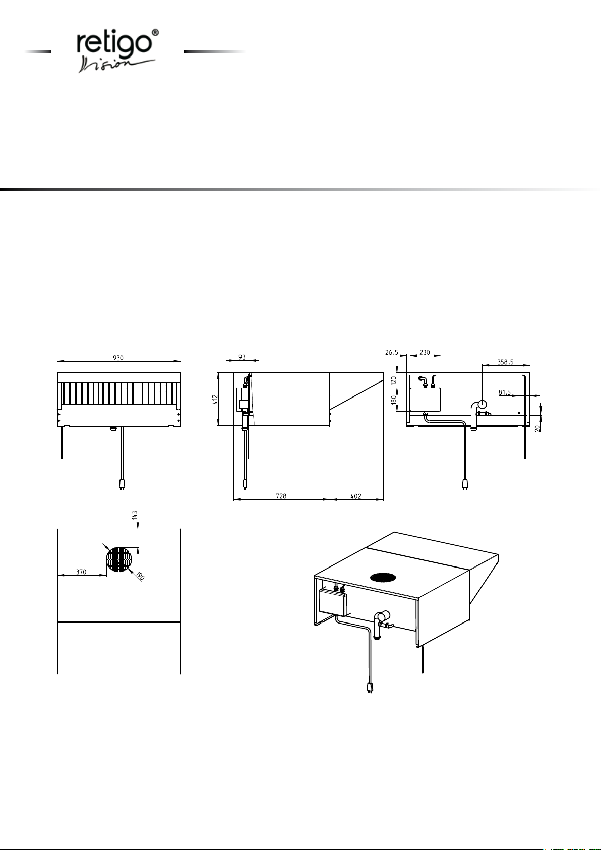
Basic technical parameters
Weight: 60 kg
Dimensions (d x w x h): 1130 x 930 x 412 mm
Noise - min./max.: 63 dB/ 68 dB
Airow max: 1000 m3/ h
Input max: 400 W
Required voltage: 1NN/ 200V-230V/ 50-60 Hz
2N/ 200V-230V/ 50-60 Hz
6
Page 9
TRANSPORT AND INSTALLATION
TRANSPORT AND INSTALLATION
1. Appliance Transportation
1.1 Appliance Transportation Instructions
When transporting this appliance, utmost care
must be exercised. Make sure that the product is not
damaged in any way.
When Receiving the Appliance:
a) Immediately after delivery, check the number of
parts according to the accompanying documents (bill
of lading, the invoice, transportation documents).
b) Check the state of packaging and the appliance.
In case of damage, please follow these steps:
- Immediately request a Damage Report, which will
describe the extent of damages.
- Make detailed photos of the damage.
- If the damage seems to be more than 10 000 CZK,
we recommend you consult a liquidator.
- Have the Damage Report certied by the driver, by
the transportation company or by an airport employee.
Packaging does not protect the appliance
from impact or from contact with sharp or
blunt objects.
After unpacking, please make sure it
contains all parts listed in the invoice.
2.2 Liquidation after useful life expiration
Please deposit the sheet metal parts to a waste
disposal centre for proper liquidation.
3. The Appliance Installation
3.1 Preparation for the Appliance Installation
• Before you start the hood installation, please discon-
nect the combi steamer from the electric sup-ply.
• Installation of the hood must be performed in accor-
dance with all relevant rules and norms valid in your
particular country.
• The hood will work properly only when installed on a
combi steamer with the following software versions or
higher:
- Blue Vision - 17.1.1
- Orange Vision - 7.12
• Unpack the hood from the delivery cartons and re-
move the protective foil.
• The hood is manufactured for a combi steamer with
the door, which opens to the right. In case you mount
the hood on a combi steamer that opens to the left,
you must replace the front hood cover. This cover is
included in your delivery package.
3.2 Placement of the Appliance on the Combi
Steamer
2. Waste Disposal
The Retigo Corporation is entitled to use the Green
point trademark in accordance with Law 477/2001
Coll., (94/62/ES), which means the cost associated
with liquidation of the packaging materials are included in the product price. According to Law 185/2001
Coll., article 10 regarding waste, you should follow
these steps:
2.1 Liquidation of packaging
Sell the cartons to a waste disposal center. Put the
protective foil and the polystyrene skeleton into waste
containers marked for plastics.
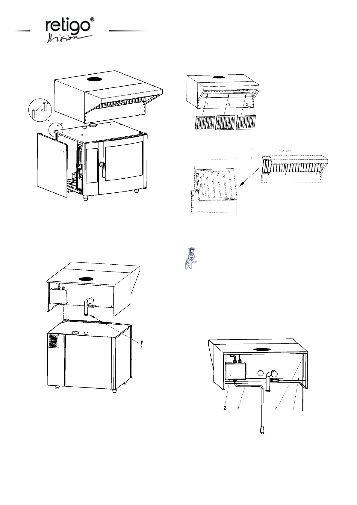
• Remove the side covers from the combi steamer
which will receive the hood. Unscrew the safety screws
with a screw driver and a wrench
Nr. 8 and replace the pins (see picture I).
• Place the hood on the combi steamer. Make sure
you correctly match the hood inlet (a pipe in the rear
part of the hood) to the combi steamer little chimney see picture II. Since the air condensation hood is quite
heavy (60 kg), make sure you have enough people
present for this task.
• Place the grease lters to the inlet opening in the
front part of the hood, these lters were delivered as
part of your package. Start with the two side lters -
picture III, as depicted in picture 1 (they are marked
with edging) and then place the middle lter between
them.
7
Page 10
TRANSPORT AND INSTALLATION
8
Picture I – Use this pins instead of screws
• Place the hood on the combi steamer. Make sure you
correctly match the hood inlet (a pipe in the rear part
of the hood) to the combi steamer little chimney – see
picture II. Since the hood is quite heavy (60 kg), make
sure you have enough workers present for this task.
Picture III - Grease lters installation
3.3 Check the installation location
Make sure that the electrical power supply meets
the parameters listed on the manufacturer’s label.
This will prevent possible installation complicati-
ons.
4. Electrical connections of the hood
• At the back side of the hood - picture IV you will nd
the M6 screw (for protective coupling) - position 1 and a
distributor pos. 2, which contains the electronic controls.
One supply cable (3 x 1.5 mm2) – position 3 and one
control cable (UTP) – pos. 4 exit the distributor.
Picture II – Placing the hood on the combi steamer
• Place the grease lters into the intake opening in the
front part of the hood; these lters were delivered as
part of your package. Start with the two side lters,
as shown in picture III. (they are marked with edging)
and then place the middle lter between them.
Picture IV – View of the back side of the hood
Page 11
TRANSPORT AND INSTALLATION
9
The hood connections to the electric supply
must be done by a qualied professional
only.
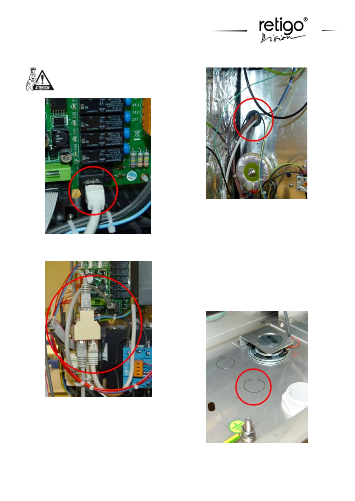
Pict. 1 - Serial bus connector RS 485 at the power
supply
Pict. 3 - The bushing in the power panel
Connecting the UTP cable
• Run the control UTP cable from the hood towards the
combi steamer’s base.
• In the base, near the supply cable opening, you will
nd capped holes. Break one of them and to this space
insert the cable grommet attached to the UTP cable.
(See picture Nr. 4.)
• In the combi steamer power panel, there is a rubber
opening near the power source plate. Run the cable
through this opening to the power source plate, as seen
on pictures Nr. 1 and Nr. 2.
Pict. 2 - Two-way adaptor RJ 45
• At the side of the power supply plate you will see the
series RS 485 serial bus connector. This connector is
designed for communication between the hood and the
combi steamer, or with a frequency converter (as seen
in picture Nr. 3.)
Pict. 4 - The opening for mounting of the UTP
cable and its housing
Page 12
TRANSPORT AND INSTALLATION
10
Connection to the Orange Combi Steamer:
Connect the hood control panel to the RS 485 serial
bus connector.
Connection to the Blue Combi Steamer:
Disconnect the RS 485 serial bus connector communication cable from the frequency converter and plug
it into the two-way splitter RJ 45 - (delivered as part
of the package) together with the air condensation
hood control cable. Now connect the two-way splitter
RJ 45 (See picture 2) with both cables to the RS 485
serial bus connector with the UTP 0.5 m cable. (See
picture 1.)
Supply Cable Connection
• The hood must be connected only to a standard
electrical grid, which meets the parameters listed on
the hood manufacturer’s label.
• The hood must be protected by a fuse of max. 16A.
• The screw marked M6, which is located at the back
side of the hood, is designed for protected connections. Connect it to a suitable lead and perform protected coupling.
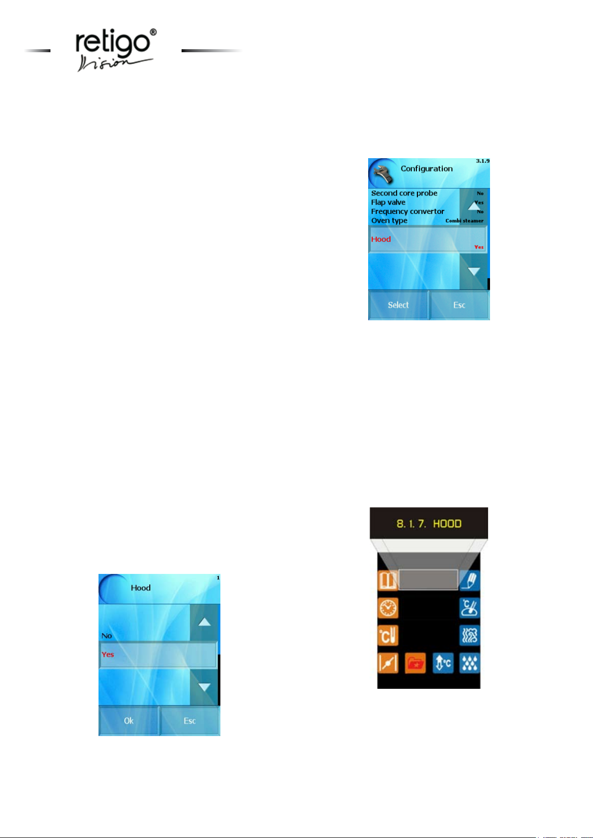
5. The hood set-up and control
• In order for the hood to work properly, it is necessa-
ry to allow communication between the hood and the
combi steamer in the combi steamer’s service menu.
Setting the hood on the combi steamer’s con-
trol panel:
After returning to the main menu by repeatedly pu-
shing the “Return“ button, the set-up is nished.
Orange:
By pushing the “Extras“ button, you will enter the special combi steamer functions section. Select option
Nr. 8 “Service“ with the up and down arrows and con-
rm your choice by pushing the “Magic” button. In the
service menu, select Nr. 8.1 „Conguration“ with the
arrows and again conrm by pushing the ”Magic“ button. Use the arrows to select „Hood“, conrm by „Magic“
button, use the arrows to select „Yes“ and conrm by
„Magic“ button. The combi steamer set-up is nished.
Now push the “Extras“ button 4 times to return to the
main menu.
Blue:
Select „Service“ at the combi steamer display, then
choose PIN ...., click OK, in the service menu select
the item “Conguration“, then select the option
“Hood“. Select Yes and conrm with OK.
Page 13
TRANSPORT AND INSTALLATION
11
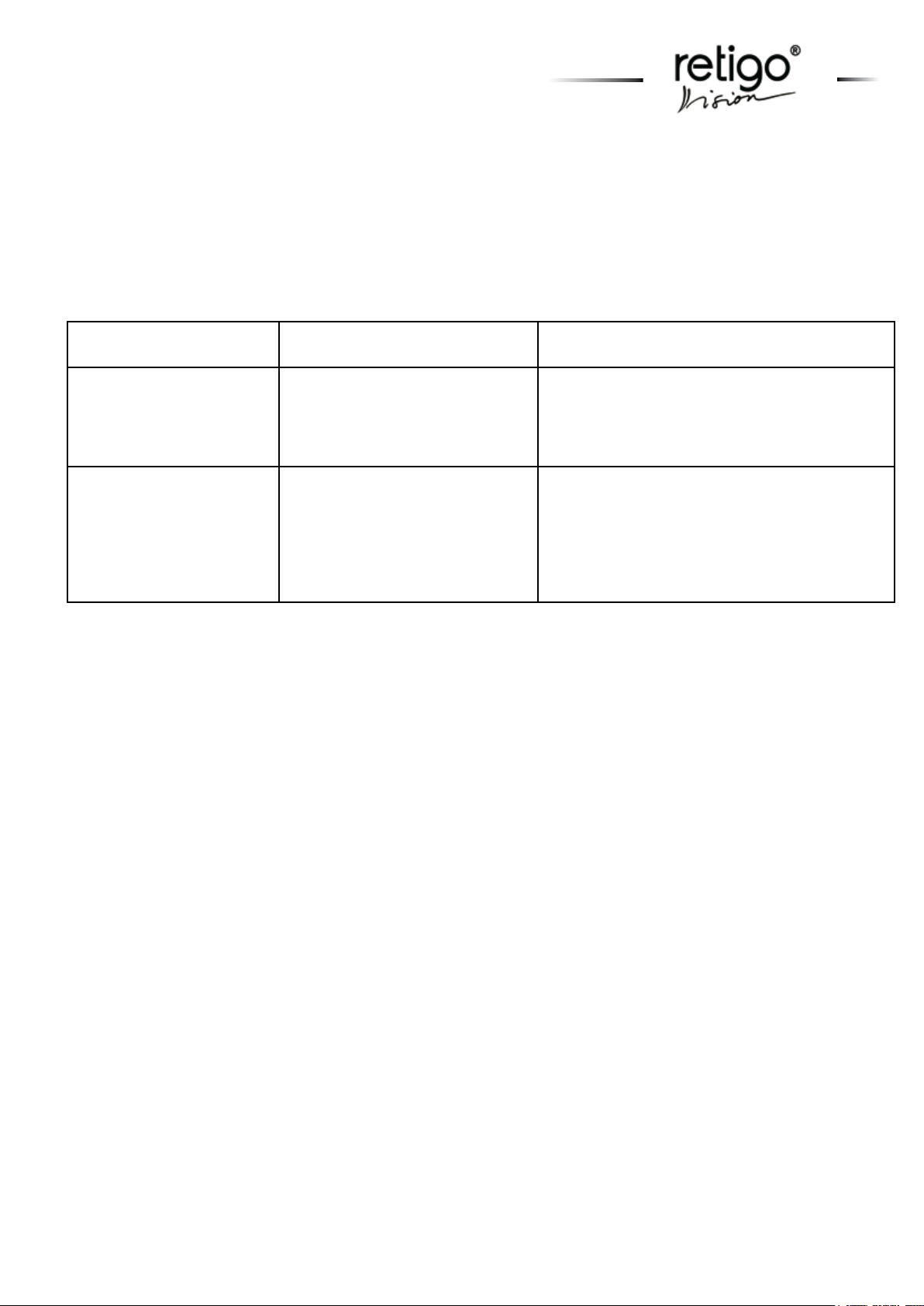
After following the above described steps, the hood will function properly. Should that not be the case, the combi
steamer display will show an error message. The message code enables you to recognize the nature of the problem.
Problems associated with the hood are marked with a code ending with the digit 5 following a decimal point (XX.5).
LIST OF THE COMBI STEAMER ERROR MESSAGES ASSOCIATED WITH THE HOOD
When Error code appears Possible cause of problem
Err 62.5 Error or interruption in the data
communication between the hood
and the combi steamer. Power supply interruption.
Err 63.5, 64.5, 65.5, 66.5,
70.5, 71.5, 72.5, 73.5
Data communications error
Error or interference of data communication between the hood and
the combi steamer.
Solution of the problem
Check the data hood communication cable and its
correct connection. Make sure the air condensation hood is plugged into the power supply.
Make sure there is not a source of interference in
the vicinity of the combi steamer (such as other
electrical device or equipment). Turn the hood
and the combi steamer off and back on. If the
error message keeps appearing, call authorized
service.
Page 14
MAINTENANCE AND CLEANING
MAINTENANCE AND CLEANING
Maintenance and cleaning must be performed by qualied personnel only. Maintenance and cleaning of the heat exchanger
should be done when decrease of perfor-
mance occurs, but at least once a year. The
grease lters can be cleaned in a dishwa-
shing machine.
Disconnect the hood from power supply and let it cool
down before you start cleaning.
The cleaning steps:
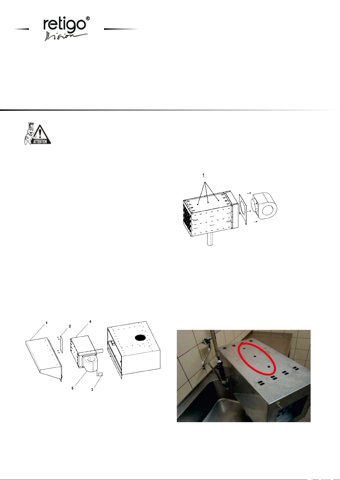
- Remove the hood from the combi steamer (see picture
V.) a place it on a suitable working table.
- Remove the grease lters.
- There are 12 M5 screws on the front side of the steam
trap. Unscrew these screws with a screw driver and
remove the steam trap from the hood – position 1.
- Unscrew the safety plate and the dividing partition –
position 2.
- Disconnect the motor power cable connector – pos. 3.
- Remove the heat exchanger – pos. 4 together with the
motor – pos. 5.
- Remove the metal sheet plate with the motor from the
exchanger.
The hood description:
The RETIGO Company recommends regular cleaning and maintenance of the appliance by a authorized
service company. Excessive wear and tear and possible
damage to the appliance can be prevented only by regular checks of the device and its cleaning.
Preventive service check must be performed after one
year of usage.
Picture VI:
1 - Service openings
Wash all the washable parts (grease lters, steam trap,
division partition) and the inside of the hood with warm
water mixed with detergent. Place the heat exchanger
to the position depicted in picture II. Insert detergent
into the exchanger through the three designated openings (see picture 5.) and leave it there for 15 minutes.
After that, rinse the exchanger with hot water. Repeat
this procedure until the exchanger is clean.
Picture V:
1 - Vapor drap
2 - Division partition
3 - Connector
4 - Heat exchanger
5 - Motor
12
Picture 5 - Service openings
Let all the parts dry and then reassemble them.
Page 15

Page 16

RETIGO Ltd.
Láň 2310, PS 43
756 64 Rožnov pod Radhoštěm
Czech republic
tel.: +420 571 665 511
fax: +420 571 665 554
e-mail: [email protected]
www.retigo.com
TSD-11-H-EN_R00
 Loading...