

Page 1
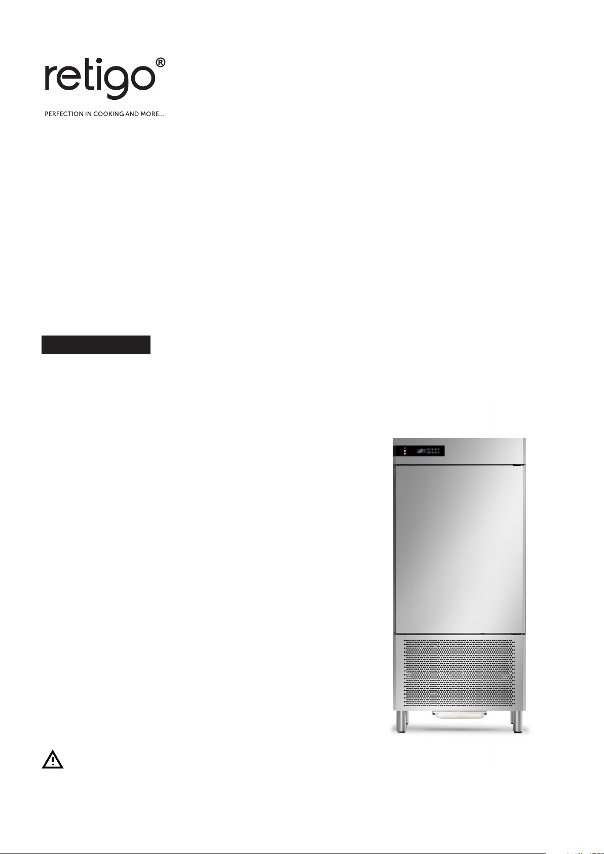
Blast chiller / freezer
Practic 1011, 1411
OPERATING MANUAL
READ THIS MANUAL BEFORE USE
Page 2

ENGLISH
1. INDEX
1. INDEX ................................................................................................................................................. 1
2. ANALYTICAL INDEX .......................................................................................................................... 2
3. SAFETY .............................................................................................................................................. 3
4. REGULATIONS AND GENERAL INSTRUCTIONS ........................................................................... 4
4.1. General information .................................................................................................................. 4
4.2. Warranty ................................................................................................................................... 4
4.3. Replacement of Parts ............................................................................................................... 4
4.4. Description of the Appliance .................................................................................................... 4
4.5. Features Plate .......................................................................................................................... 5
4.6. Safety Devices ......................................................................................................................... 6
5. USE AND FUNCTIONING .................................................................................................................. 7
5.1. Description of the Functioning Cycles ...................................................................................... 7
5.2. Description of Controls ............................................................................................................. 8
5.3. Functioning ............................................................................................................................... 9
5.4. Recommendations for Use ..................................................................................................... 15
6. CLEANING AND MAINTENANCE ................................................................................................... 16
GB
6.1. Recommendations for Cleaning and Maintenance ................................................................ 16
6.2. Routine Maintenance ............................................................................................................. 16
6.3. Extraordinary maintenance .................................................................................................... 17
7. TROUBLESHOOTING ..................................................................................................................... 19
7.1. Faults Display ......................................................................................................................... 20
8. INSTALLATION ................................................................................................................................ 21
8.1. Packaging And Unpacking ..................................................................................................... 21
8.2. Installation .............................................................................................................................. 22
8.3. Electric Power Supply Connection ......................................................................................... 22
8.4. Inspection ............................................................................................................................... 23
8.5. Programming the settings ...................................................................................................... 23
9. DISPOSAL OF THE APPLIANCE .................................................................................................... 24
10.REFRIGERANT TECHNICAL CARD ............................................................................................... 24
ATTACHMENTS ....................................................................................................................................... I
1
Page 3

ENGLISH
2. ANALYTICAL INDEX
GB
B
Blast chilling Cycle; 16
C
Cancelling the list of HACCP alarms; 14
Cleaning the condenser; 18
Cleaning the evaporator; 17
Compressor operating hours; 14
Cooling Cycle; 12
Core Probe Heating; 13
D
Defrosting; 7; 12
Description of Controls; 8
Description of the Appliance; 4
Display of Temperatures; 13
Disposal of the Appliance; 24
E
Electric Power Supply Connection; 22
Evaporator Fan Micro switch; 6
F
Faults Display; 20
Features Plate; 5
G
General information; 4
H
HACCP Alarms; 13
HACCP alarms display; 13
Hard Temperature Blast Chilling cycle; 9
Hard Time Blast Chilling cycle; 10
High pressure safety pressure switch; 6
I
Inspection; 23
Installation; 22
K
Keyboard lock; 13
P
Packaging; 21
Preservation; 7
Programming the settings; 23
Prolonged Inactivity; 15
Protective Fuses; 6
R
Recommendations for Cleaning and Maintenance;
16
Recommendations for normal use; 15
Recommendations for Use; 15
REFRIGERANT TECHNICAL CARD; 24
Replacement of Parts; 4
Replacing the fuses; 18
Routine Maintenance; 16
S
SAFETY; 3
Safety Devices; 6
Shock freezing Cycle; 16
T
Temperature Blast Chilling; 7
Temperature Shock Freezing; 7; 11
Time and Date SET; 14
Time Blast Chilling; 7
Time Blast Chilling cycle; 10
Time Defrosting; 12
Time Shock Freezing; 7; 11
U
Unpacking; 21
W
Warranty; 4
2
Page 4

3. SAFETY
ENGLISH
!It is recommended to carefully
read the instructions and warnings
contained in this manual before using
the appliance. The information
contained in the manual is
fundamental for the safety of use and
for machine maintenance.
! Keep this manual carefully so that it can be
consulted when necessary.
The electric plant has been designed in
compliance with the IEC EN 60335-2-89
Standard.
! Maintain ventilation openings in the
appliance casing or in the built-in structure free
from all obstructions.
! Do not use mechanical devices or other
means to accelerate the defrosting process, other
than those recommended by the manufacturer.
! Do not damage the coolant circuit.
! Do not use electrical appliances inside the
appliance compartments for storage of frozen
food.
! Do not store explosives, such as pressurised
containers with flammable propellant, in this unit.
! Do not place anything on the bottom of the
device. Use the appropriate racks to store the
product.
! If a stationary appliance is not fitted with a
supply cord and a plug, the means for
disconnection must be incorporated in the fixed
wiring in accordance with the wiring rules.
In the design and construction phase, the
manufacturer has paid particular attention to the
aspects that can cause risks to safety and health
of persons that interact with the appliance.
Carefully read the instructions stated in the
manual and those applied directly to the machine,
and particularly respect those regarding safety.
Do not tamper with, evade, eliminate or by-pass
the installed safety devices. Failure to comply with
this requisite can lead to serious risks for personal
health and safety.
It is recommended to simulate some test
manoeuvres to identify the controls, in particular
those relative to switch-on and switch-off and their
main functions.
The appliance is only destined for the use for
which it has been designed; any other use must
be considered improper.
The manufacturer declines all liability for any
damage to objects or injury to persons owing to
improper or incorrect use.
All maintenance interventions that require
precise technical skill or particular ability must be
performed exclusively by qualified staff.
! When using the appliance, never obstruct
the air inlet when the appliance is on, so as not to
compromise its performance and safety.
GB
! The maximum permissible load for the racks
is 45kg evenly distributed.
if the supply cord is damaged, it must be
replaced by the manufacturer, its service agent or
similarly qualified persons in order to avoid
hazard.
, Specific adhesives highlight the presence of
mains voltage in the proximity of areas (however
protected) with risks of an electrical nature.
In order to guarantee hygiene and protect the
foodstuffs from contamination, the elements that
come into direct or indirect contact with the
foodstuffs must be cleaned very well along with
the surrounding areas. These operations must
only be performed using detergents that can be
3
Page 5

ENGLISH
GB
used with foodstuffs, avoiding inflammable
products or those that contain substances that are
harmful to personal health.
In the case of prolonged inactivity, as well as
disconnecting all the supply lines, it is necessary
to accurately clean all internal and external parts
of the appliance.
4. REGULATIONS AND GENERAL INSTRUCTIONS
4.1. General information
This manual has been designed by the
manufacturer to provide the necessary information
to those who are authorised to interact with the
appliance.
The persons receiving the information must read it
carefully and apply it strictly.
Reading the information contained in this
document will allow the user to prevent risks to
personal health and safety.
Keep this manual for the entire operating life of
the equipment in a place which is well-known and
easily accessible, so that it is always available
when its consultation becomes necessary.
4.2. Warranty
The warranty of the equipment and the
components we produce has duration of 2 years
from the date of delivery and translates into the
supply, free of charge, of parts that we consider to
be faulty.
These faults must, however, be independent from
incorrect use of the product in compliance with the
indications stated in the manual.
4.3. Replacement of Parts
Particular symbols have been used to highlight
some parts of the text that are very important or to
indicate some important specifications. Their
meanings are given below:
! Indicates important information
regarding safety. Behave appropriately so as
not to risk the health and safety of persons or
cause damage.
Important
Indicates particularly important technical
information that must not be ignored.
Fees deriving from labour, journeys and transport
are excluded from the warranty.
The materials replaced under warranty are our
property and must therefore be returned under the
responsibility and expense of the customer.
Caution - Warning
! Activate all envisioned safety devic es before
carrying out any replacement intervention.
In particular, deactivate the electrical power
supply using the differential isolating switch.
Only use original spare parts to replace worn
components.
4.4. Description of the Appliance
The Blast chiller-Shock freezer, from now on
defined as appliance, has been designed and built
to cool and/or freeze foodstuffs in the professional
catering ambit.
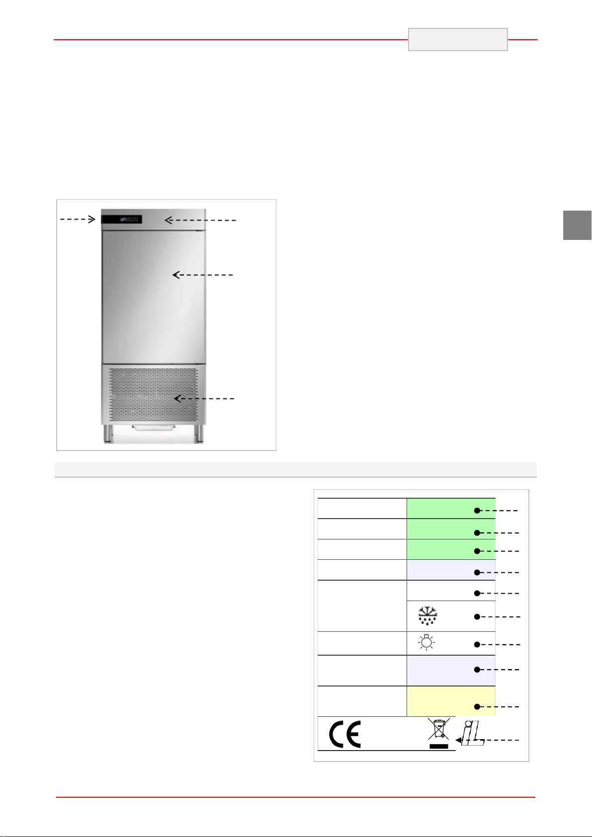
1) condensation area: it is positioned in the
lower part and is characterised by the
presence of the condensing unit.
All responsibility is declined for injury to
persons or damage to components deriving from
the use of non-original spare parts and
interventions which could modify the safety
requisites, without authorisation of the
manufacturer.
2) electric area: it is positioned in the upper
part of the appliance and contains the
control and power supply appliance as
well as electric wiring.
3) evaporation area: it is situated inside the
refrigerated compartment in the rear and
is characterised by the evaporating unit.
4
Page 6
ENGLISH
4) storage area: it is situated inside the
refrigerated compartment and is destined
for the cooling and/or freezing of
foodstuffs.
The upper part is also distinguished by a control
panel (A) that allows access to the electric parts;
there is a vertically-opening door in the front,
which closes the refrigerated compartment
hermetically.
A
2
3 - 4
Depending on requirements, the appliance is
produced in several versions.
10 TRAY BLAST CHILLER-SHOCK FREEZER
Model suitable to contain 10 trays with
blast chilling capacity of 28 and 18 in
shock freezing.
14 TRAY BLAST CHILLER-SHOCK FREEZER
Model suitable to contain 14 trays with
blast chilling capacity of 38 and 25 in
shock freezing.
GB
1
4.5. Features Plate
The identification plate shown is applied directly
onto the appliance. It states the references and all
indications indispensable for working in safety.
1) Appliance code
2) Description of the appliance
3) Serial number
4) Power supply voltage and frequency
5) Rated output
6) Defrosting output
7) Total light output
8) Climatic class
9) Type and Amount of refrigerant gas
10) WEEE symbol
CODE /KODE
CODICE
MODEL / MODELL
MODELLO
SE RIA L No/SERIE N NR.
MATRICOLA
TENSION/SPANNUNG
TENSIONE
INPUT
LEISTUNGSAUFNHAME
POTENZA
1
2
3
4
5
6
7
CLIMATIC CLASS
KLIMAKLASSE
CLASSE CLIMATICA
REFRIGERANT
KUEHLMITTEL
REFRIGERANTE
8
9
10
5
Page 7
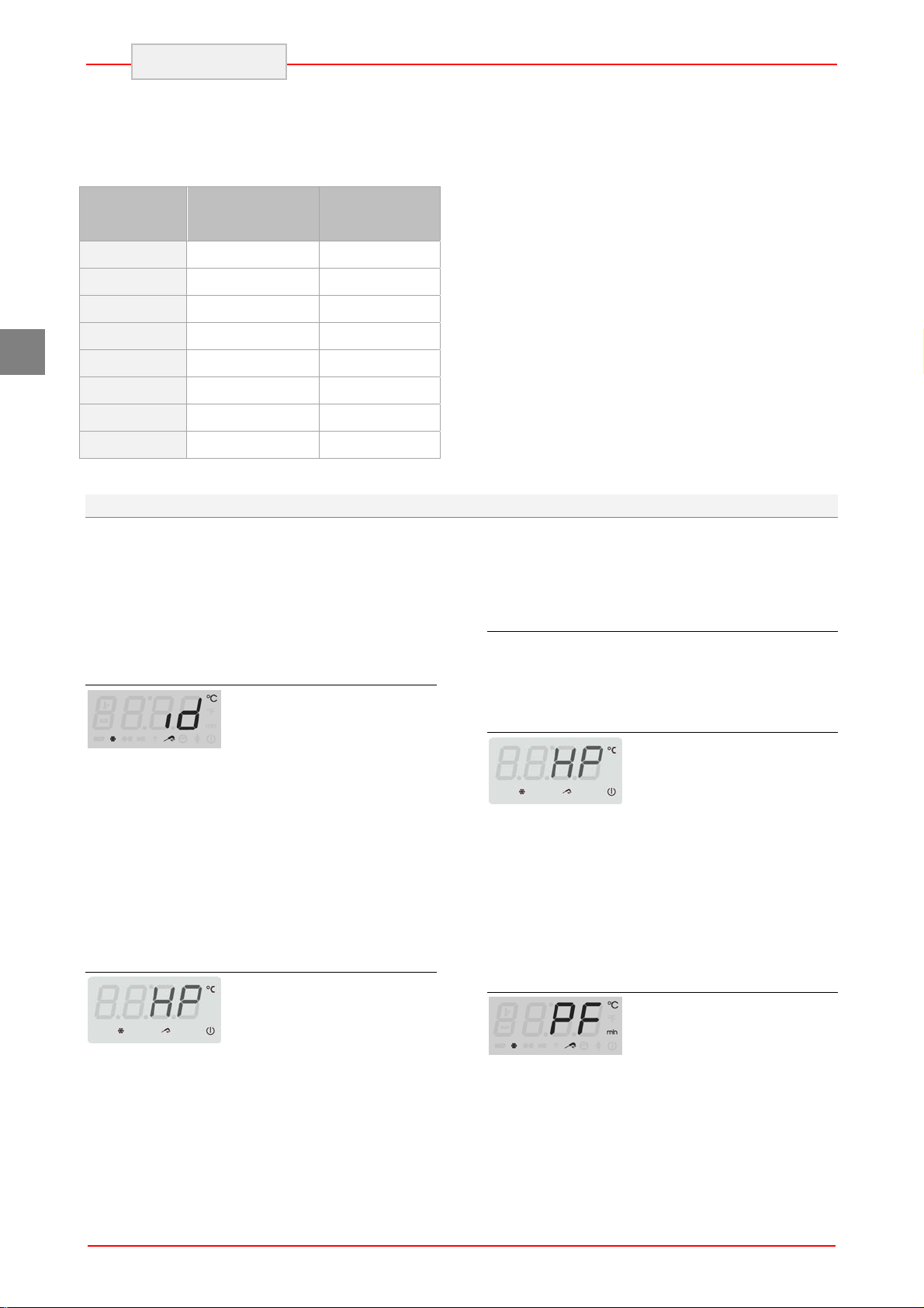
The appliances are equipped with climatic class that indicates the room temperature within which the
refrigerator is operating correctly.
The following climatic classes exist:
Climatic
Class
0
ENGLISH
Room
Temperature
Related
Humidity
°C
20 50
%
GB
1
2
3
4
6
5
7
16 80
22 65
25 60
30 55
27 70
40 40
35 75
4.6. Safety Devices
During the running of appliance, some control
devices may activate and govern the correct
running of the machine. In other cases, they may
deactivate parts or the whole machine, to put the
appliance in safe conditions. Main controls are
described below.
Micro Door
In case the door is opened,
the magnetic switch placed on the control board
opens and, during blast-chilling or shock-freezing,
evaporator fans go off ; if the opening persist for a
longer period than the one established on
parameter i2, it will appear on the display the
alarm “id” together with a sound signal (until the
door is closed).
That condition may also be determined when the
door is not perfectly aligned to or near the control
board.
High pressure safety pressure switch
The alarm is represented on the display with the
code “HP”.
Protective Fuses
Some protection fuses in the general power
supply line are activated in case of overload.
Other fuses are prepared for the evaporator fans
Evaporator Fan Micro switch
If the deflector is opened to
inspect the evaporator or fans, this micro switch
positioned on the evaporator deflector,
deactivates machine functioning. Closure of the
deflector with the successive disappearance of
the alarm on the display, restores normal machine
functioning.
The alarm is represented on the display with the
code “HP”.
Electrical Power Supply Failure
In the event of room conditions
or functional anomalies, which cause the
refrigerating circuit to exceed the maximum
pressure values, the MAX safety switch is
activated, stopping the machine. When an
acceptable pressure value is reset, it is possible to
run the machine.
In the event of a power failure
during a working cycle for a period exceeding the
value established on parameter A10, once
restored the electricity the display will show the
alarm “PF”.
6
Page 8
5. USE AND FUNCTIONING
5.1. Description of the Functioning Cycles
The following are brief descriptions and types of
operating cycles.
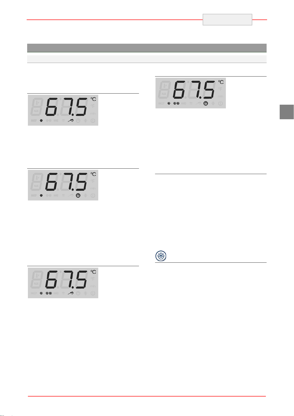
Temperature Blast Chilling
This cycle allows
a reduction in temperature in the product core
from +90°C to +3°C as quickly as possible and
within a MAX time of 90 minutes. The cycle ends
when the value +3°C, read by the needle probe, is
reached.
Time Blast Chilling
This cycle allows
a reduction in temperature in the product core
from +90°C to +3°C during the set time: we
remind you that it is advisable to run some
previous testing temperature cycles in order to
determine the necessary time for a correct
product blast chilling process. Do not forget that
acquired times have to be considered valid for
exclusive use of the same type of product and in
the same quantities per cycle.
Temperature Shock Freezing
This cycle allows
a reduction in temperature in the product core
from +90°C to -18°C in the quickest time possible
and within a MAX time equal to 270 minutes. The
cycle ends when the value -18°C, read by the
needle probe, is reached.
ENGLISH
Time Shock Freezing
This cycle allows
a reduction in temperature in the product core
from +90°C to -18°C during the set time: we
remind you that it is advisable to run some
previous testing temperature cycles in order to
determine the necessary time for a correct
product blast chilling process. Do not forget that
acquired times have to be considered valid for
exclusive use of the same type of product and in
the same quantities per cycle.
Preservation
At the end of each cycle as described above,
either temperature or time cycle, the preservation
cycle will be started automatically, with no time
limit. The freezer temperature will refer to last
cycle, just concluded:
+ 3°C for blast chilling
-25°C for shock-freezing
Warning: use of this cycle is recommended only
for short periods prior to storage of the product in
a storage unit or in case of emergency, so as to
avoid such a limited use of a machine with such
high potential.
Defrosting
The frost forming on the evaporator following the
deposit of humidity from the product can
jeopardise the correct functioning of the
appliance. A defrosting cycle must be carried out
to restore full functionality.
Defrosting is performed by forced ventilation using
the evaporator fan. The cycle can be performed
with the door open or closed and can also be
interrupted at any time.
GB
7
Page 9
ENGLISH
5.2. Description of Controls
GB
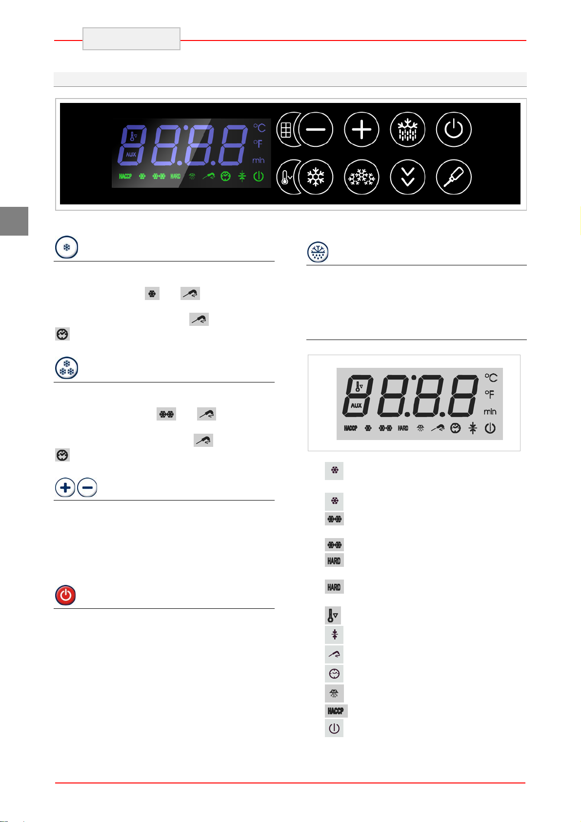
Below a brief description of the functions
performed by the control panel buttons.
Blast Chilling Key
Pressing the key with machine still, allows the
selection of a temperature blast chilling cycle
(+90°C+3°C). Led
A second pressure of the key allows to select a
timed blast chilling cycle: led
turns on.
Shock Freezing Key
Pressing the key with machine still, allows the
selection of a temperature shock freezing cycle
(+90°C-18°C). ). Led
A second pressure of the key allows to select a
timed shock freezing cycle: led
turns on.
Time setting Keys
If timed chilling or freezing mode has been
selected, these keys make it possible to set the
number of minutes the cycle will last.
If temperature chilling or freezing mode has been
selected, these keys make it possible to set the
end chilling or freezing temperature.
Start Key
Once chosen the needed cycle, it can be started
by pressing this key,
If pressed during functioning, the machine will
stop; the previously chosen cycle will persist and
can be run immediately.
By pressing this button for at least 5 seconds the
machine passes to the stand-by mode. Repeat
the procedure to reactivate the board.
and are on.
is off and led
and turn on.
is off and led
DEFROST Key
When the machine is off a manual defrosting
cycle can be started.
If the key is pressed again, the defrosting in
progress can be stopped.
Display: symbols description
: new HACCP alarms stored
blinking: a blast chilling cycle has been
selected.
on: running blast chilling cycle.
blinking: a shock freezing cycle has been
selected.
On: running shock freezing cycle.
blinking: an intensive blast chilling or
shock freezing cycle has been selected.
on: an intensive blast chilling or shock
freezing cycle is running.
: over cooling function on
: preserving cycle on
: temperature cycle on
: timed cycle on
: defrosting cycle on
8
: stand-by mode
Page 10
5.3. Functioning
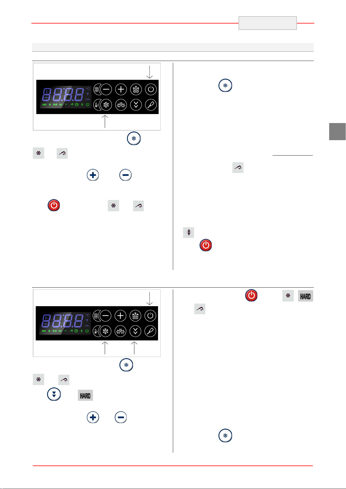
Temperature Blast chilling
2
ENGLISH
During blast chilling the display shows the
temperature detected by the core probe. By
1
Select the blast chilling by pressing
and will blink. The display shows the end
blast chilling temperature value.
By pressing the
temperature value (+3°C) can be changed.
Insert the core probe into the product.
Press
permanently on.
The test for the proper insertion of the probe will
start.
If the test gives a positive result, the blast chilling
cycle starts, in case of negative result the
machine will run a timed blast chilling (see proper
chapter)
Hard Temperature Blast Chilling cycle
key to start. Led and will be
and keys the
key: led
pressing the
the chamber probe can be visualized.
If the product temperature reaches the
established value within the set blast chilling time,
the cycle is considered as completed and a
preserving cycle is automatically started and an
intermittent sound confirm the correct conclusion
of the cycle.
In case the product temperature does not reach
the on parameter r5 established value, the cycle
continues: the led
an intermittent sound. To stop the alarm press a
key.
As soon as product temperature is lower than the
established value the blast chilling cycle is
considered as completed and a preserving cycle
is automatically started.
During preservation the display shows the
temperature detected by the chamber probe; LED
is switched on.
Press
to conclude the preservation cycle.
key, temperature detected by
will blink accompanied by
GB
3
1
Select blast chilling by pressing
and will blink. To select the hard cycle
press
The display show the end blast chilling
temperature. Using
blast chilling temperature (+3°C) can be changed.
Insert the core probe into the product. Start the
: LED blinks.
and key the end
2
key: LEDs
cycle by pressing the
and
The test for the proper insertion of the probe will
start.
If the test gives a positive result, the blast chilling
cycle starts, in case of negative result the
machine will run a timed blast chilling (see proper
chapter)
The working set point of the hard phase is
established on parameter r9. Once the
temperature detected by the core probe
corresponds to the value established on
parameter r13, the hard phase is considered as
completed.
During blast chilling the display shows the
temperature detected by the core probe. By
pressing the
the chamber probe can be visualized.
are permanently on.
key, temperature detected by
key. LED ,
9
Page 11
ENGLISH
GB
If the product temperature reaches the
established value within the established blast
chilling time, the cycle is considered as completed
and a preserving cycle is automatically started
and an intermittent sound confirm the correct
conclusion of the cycle.
In case the product temperature does not reach
the on parameter r5 established value, the cycle
continue: the led
an intermittent sound. To stop the alarm press a
key.
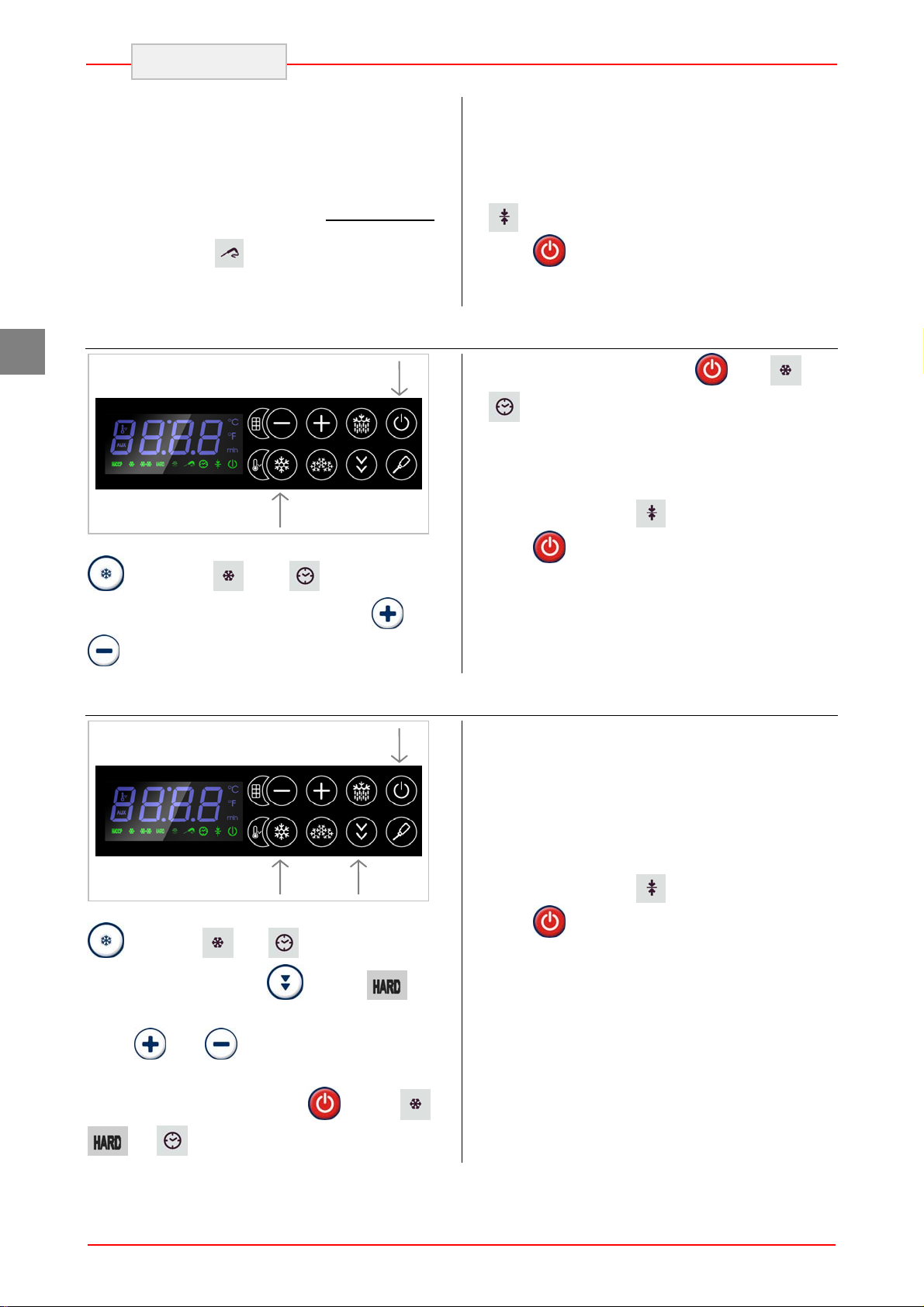
Time Blast Chilling cycle
Select blast chilling cycle by pressing key
twice: LED and will blink. The
will blink accompanied by
2
1
As soon as product temperature is lower than the
established value the blast chilling cycle is
considered as completed and a preserving cycle
is automatically started.
During preservation the display shows the
temperature detected by the chamber probe; LED
is switched on.
Press
Start the cycle by pressing:
At the end of the set time, the blast chilling cycle
is concluded and the preserving cycle is
automatically started. During preservation the
display shows the temperature detected by the
chamber probe, LED
Press
to conclude the preservation cycle.
. LED and
are permanently on.
is switched on.
to conclude the preservation cycle.
display shows the cycle duration. Using
keys the blast chilling time can be changed.
Hard Time Blast Chilling cycle
1
Select blast chilling cycle by pressing key
twice: LED and will blink. To select
the hard cycle press the
blink.
Using
can be changed.
and keys the blast chilling time
2
key: LED will
and
3
The working set point of the hard phase is
established on parameter r9. At the end of the on
parameter r14 set time, the hard phase is
considered as concluded.
At the end of the set time, the blast chilling cycle
is concluded and the preserving cycle is
automatically started. During preservation the
display shows the temperature detected by the
chamber probe, LED
Press
to conclude the preservation cycle.
is switched on.
Start the cycle by pressing:
and are permanently on.
. LED ,
10
Page 12
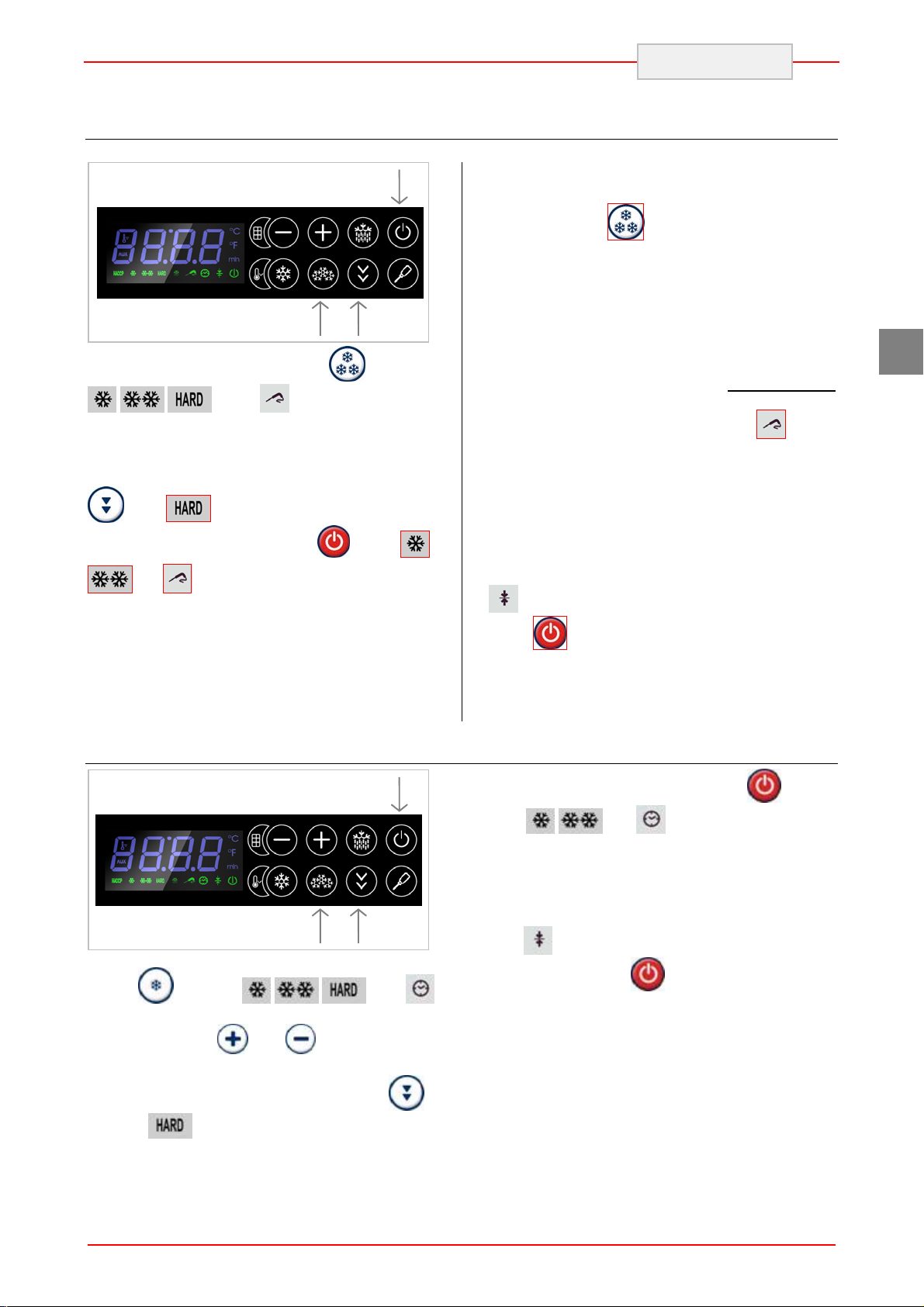
Temperature Shock Freezing
3
ENGLISH
During shock freezing the display shows the
temperature detected by the core probe.
1
Select shock freezing by pressing
, , and blink. The display
shows the end cycle temperature. Using the and
keys the end shock freezing temperature (-18°C)
can be changed. Insert the core probe into the
product. To select the SOFT cycle press the key
. LED will turn off.
Start the cycle by pressing key
and are permanently on.
The test for the proper insertion of the probe will
start.
If the test gives a positive result, the blast chilling
cycle starts, in case of negative result the
machine will run a timed blast chilling (see proper
chapter).
Time Shock Freezing
2
key: LED
. LED ,
By pressing the
by the chamber probe can be visualized.
If the product temperature reaches the
established value within the established time set
on parameter r6, the cycle is considered as
completed: a preserving cycle is automatically
started and an intermittent sound confirm the
correct conclusion of the cycle.
In case the product temperature does not reach
the established value within the maximum time
allowed, the cycle continue: LED
accompanied by an intermittent sound. To stop
the alarm press any key.
As soon as product temperature is lower than the
established value the shock freezing cycle is
considered as completed and a preserving cycle
is automatically started.
During preservation the display shows the
temperature detected by the chamber probe; LED
is switched on.
Press
to conclude the preservation cycle.
key, temperature detected
blinks
GB
3
1
Select the freezing process pressing twice the
button
blink. The display shows the time of the cycle.
Using the buttons
the time of freezing
To select a soft cycle, press the button
the LED
, the leds , , and
and you can change
will turn off.
2
:
To start the cycle, press the button
leds,
At the end of the setted time, the freezing cycle is
completed and automatically starts a cycle of
conservation.
During the storage phase the display shows the
temperature measured by the room probe, the
LED
Press the button
conservation.
, and remain lit steadily.
is turned on.
to end the cycle of
:. The
11
Page 13
Time Defrosting
ENGLISH
GB
3
1
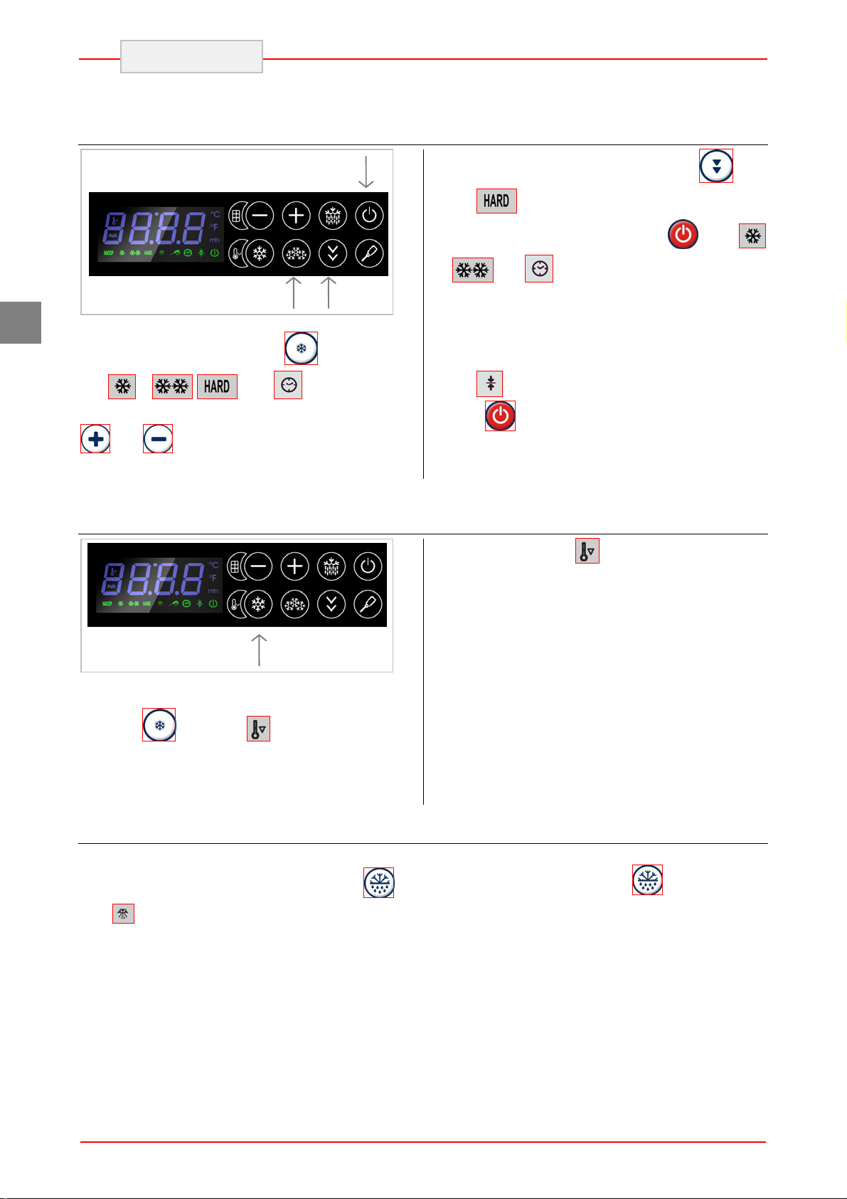
Select defrosting by pressing
LED
display shows the cycle duration. By using the
changed.
Cooling Cycle
, , and blink. The
and keys, the freezing time can be
2
key twice:
To select the SOFT cycle press the key.
LED
Start the cycle by pressing key
,
Once the set time is over, the shock freezing cycle
is considered as completed and a preserving
cycle is automatically started.
During preservation the display shows the
temperature detected by the chamber probe;
LED
Press
continue, LED
accompanied by a one second sound signal.
will turn off.
. LED
and are permanently on.
is switched on.
to conclude the preservation cycle.
is permanently on
1
Select the cooling cycle by pressing for two
seconds
cycle will be started. The working set point is
established on parameter r12. When the chamber
temperature reaches the set value, the cycle
Defrosting
First make sure there is no preservation cycle
running. Press for at least four seconds key
LED
Defrosting is performed by forced ventilation using
the evaporator fan. The cycle can be performed
key: LED blinks: a cooling
will be switched on.
:
with the door open or closed and can also be
interrupted at any time using
key.
12
Page 14
Keyboard lock
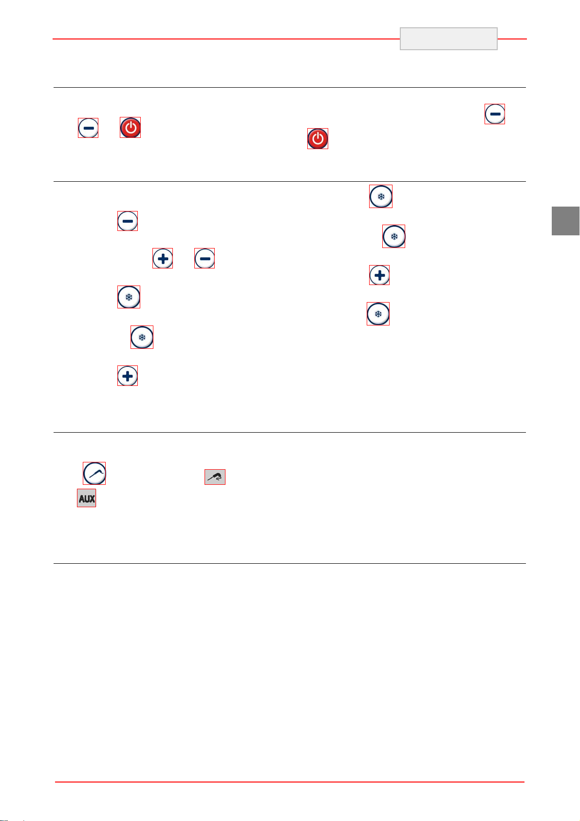
It is possible to lock the keyboard. By pressing the
keys
show “Loc” for one second.
Display of Temperatures
Make sure the keyboard is not blocked and that
there is no cycle running.
and for a second: the display will
Press
shows the first available message.
By using keys
“Pb1” message (chamber probe).
Press
detected by the chamber probe.
Pressing
“Pb1”.
key for a second: the display
and select the
to visualize the value
the display will again show
ENGLISH
To unlock the keyboard, press the keys
for a second: the display will show “Unl” for
one second.
Press
detected by the core probe.
Pressing
“Pb2”.
Press
message “Pb4” (condenser probe).
Press
detected by the condenser probe.
to visualize the value
the display will again show
key: the display will show the
to visualize the value
and
GB
Press
message “Pb2” (core probe).
Core Probe Heating
Make sure the keyboard is not blocked and there
is no cycle running.
Press
LED
When the temperature detected by the core probe
reaches the value established on parameter u7,
HACCP Alarms
The device can store up to 9 different HACCP
alarms, thereafter a new one will overwrite the
oldest one. The device gives following
information:
Alarm code
critical value
date and time when die alarm occurred
Alarm duration (from 1 min to 9 9h and 59
Below a list of existing codes:
time: temperature blast chilling/shock
AH: maximum temperature alarm during
key for a second: LED blinks and
turns on.
min, partial if the alarm is still active).
freezing alarm, the cycle exceeded the
time limit. the alarm stores the
temperature detected by the core probe at
the end of the established time.
preservation. The alarm stores the
key: the display will show the
the cycle is concluded, a sound signal is activated
for one second.
maximum temperature of the chamber
probe.
PF power supply failure during
preservation. The alarm stores the room
temperature when restoring electricity.
To avoid having to memorize power failure
alarms repeatedly, disconnect the power supply
when the tool is in stand-by mode.
If the duration of the power failure alarm is
such that it causes a clock error (code “rtc”), the
device will not provide any information regarding
the duration of the alarm
13
Page 15
GB
HACCP alarms display
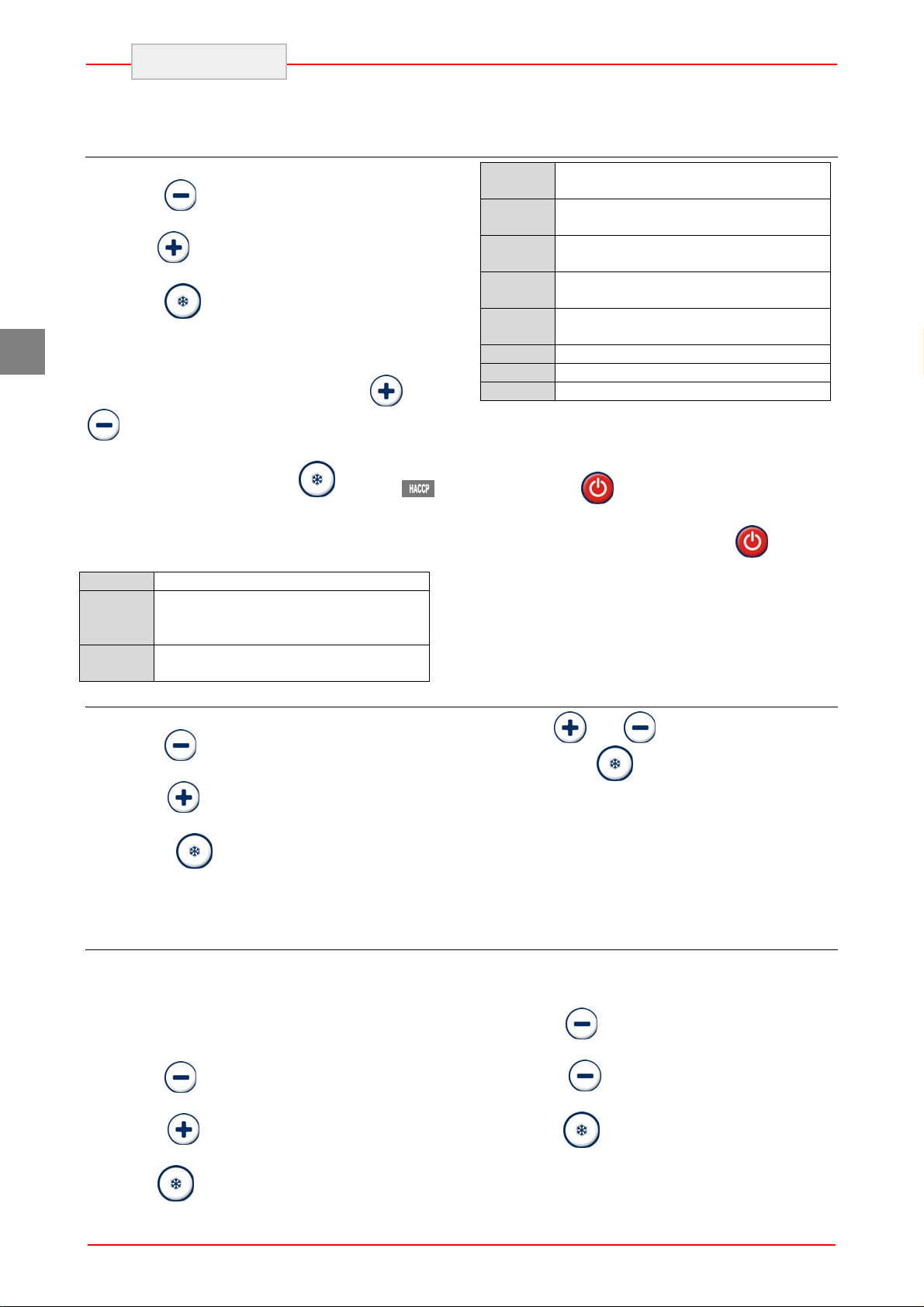
Make sure the keyboard is not locked.
Keep the
screen will display the letters "rtc".
Press the
appear.
Press the
code for the most recent alarm (in other words
one of the codes listed above followed by number
"1"; the greater the number that follows the code
for the alarm, the older it is). With the
keys it is possible to scan the various
memorised alarms.
ENGLISH
key pressed for 1 second: the
key repeatedly until the letters "LS"
key: the screen will display the
and
n03
d26
h16
n30
dur
h01
n15
AH3
The screen displays every piece of information for
1 second.
To exit the sequence of information: press and
the alarm was set off in the month of
March (continue ...)
the alarm was set off on March 26,
2009
the alarm was set off at16:00
(continue ...)
the alarm was set off at16:30
(continue ...)
the screen will display the duration of
the alarm
the alarm lasted for 1 h (continue ...)
the alarm lasted for 1 h and 15 min
the selected alarm
To select an alarm press the
led will stop flashing and stay on steadily, the
screen will display the following information in
sequence :
8.0
StA
y09
Cancelling the list of HACCP alarms
Make sure the keyboard is not locked.
Keep the
screen will display the letters "rtc".
Press the
"rLS" appear.
Press the
requested in order to cancel the alarms from the
memory.
Compressor operating hours
The tool is capable of memorising up to 9,999
hours of compressor operation, after which the
number “9999” will flash.
To view the hours of compressor operation follow
the instructions below.
Make sure the keyboard is not locked.
the critical value is 8.0 °C/8 °F
the screen is about to display the
date and time when the alarm
was set off
the alarm was set off in 2009
(continue ...)
key pressed for 1 second: the
key repeatedly until the letters
key: the password will be
key: the
release the
selected alarm (“AH3” in the example).
To exit the procedure press the
screen will display the temperature read by the
cold room probe again.
key, the screen displays the
key: the
If the tool does not have any alarms in its
memory, the “LS” label will not be displayed.
With the
149 : press the
the alarms.
and keys enter the password
key to confirm the deletion of
If the tool does not have any alarms in its
memory, the “rLS” label will not be displayed.
To reset the counter to zero follow the instructions
below.
Make sure the keyboard is not locked.
Keep the
screen will display the letters "rtc".
key pressed for 1 second: the
Keep the
screen will display the letters "rtc".
Press the
"CH" appear.
Press the
key pressed for 1 second: the
key repeatedly until the letters
key to view the data.
Press the
"rCH" appear.
Press the
order to reset the counter to zero.
14
key repeatedly until the letters
key: the password is required in
Page 16
ENGLISH
With the and keys enter the password
Time and Date SET
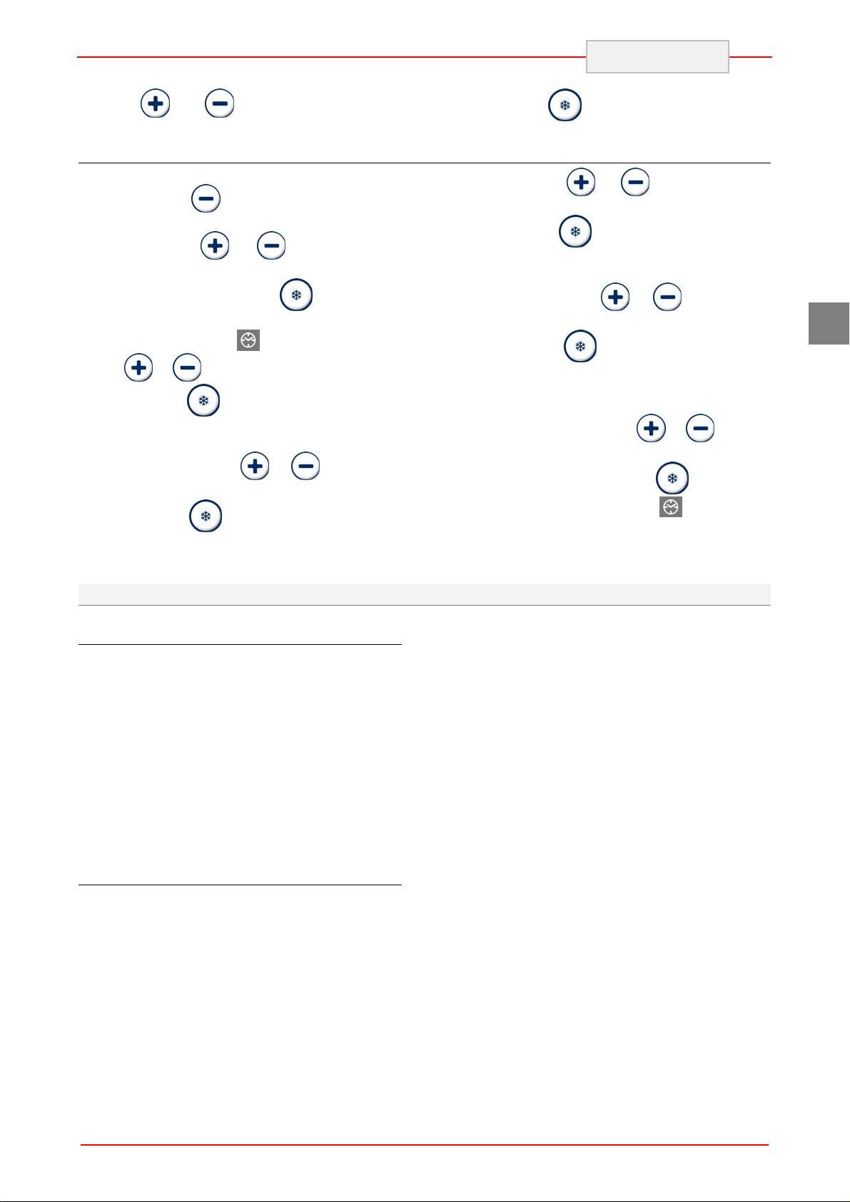
Make sure the keyboard is not locked.
Press the button
will show the first label available
Press the button
shows "rtc".
Press and release the button
will show "yy" followed by the last two numbers of
the year and the LED
button
Press the button
to the modification of the month : the display will
show “nn” followed by the two numbers of the
month. Using the button
the current month.
Press the button
to the modification of the day : the display will
show "dd" followed by the numbers of the day.
or you can set the current year.
for one second, the display
or until the display
: the display
will flash. Using the
to save the data and move
or you can set
to save the data and move
5.4. Recommendations for Use
Prolonged Inactivity
If the appliance remains inactive for a long period,
proceed as follows:
1. Use the automatic isolating switch to
deactivate connection to the main electrical
line.
2. Clean the appliance and surrounding areas
thoroughly;
3. Spread a thin layer of cooking oil onto the
stainless steel surfaces;
4. Carry out all maintenance operations;
5. Leave the doors ajar to prevent the formation
of mould and/or unpleasant odours.
Recommendations for normal use
In order to ensure correct use of the appliance, it
is advisable to apply the following
recommendations.
! Do not obstruct the zone in front of the
condensing unit in order to favour heat disposal
from the condenser to a maximum.
Always keep the front of the condenser clean.
149 : press the
Using the button
current day.
Press the button
to the modification of the hour : the display will
show "hh" followed by the two numbers of the
hour. Using the button
the current hour.
Press the button
move to the modification of the minutes : the
display will show “nn” followed by the two
numbers of the minutes. The time is shown in 24
hour format. With the button
set the correct value.
Press and release the button
operate for 15 seconds, the LED
If possible, a brief external period is useful to
lower the temperature to acceptable values.
Check the planarity of the appliance rest surface.
key to confirm.
or you can set the
to save the data and move
or you can set
to save the data and
or you can
or do not
will turn off.
Do not stack the materials to be preserved
in contact with the internal walls, so blocking the
circulation of air, which guarantees uniformity of
the internal temperature of the refrigerated
compartment.
There must be a sufficient space between
the basins and trays used in order to guarantee a
sufficient flow of cold air on the entire product.
Therefore avoid the following positions of trays
and/or basins stated below.
Never obstruct the inlet of the evaporator
fans.
Products that are more difficult to chill
because of their composition and size should be
placed in the centre.
GB
Do not insert foodstuffs that are well above
the temperature of 90°C. As well as initially
overloading the machine it can make protections
intervene that prolong temperature descent times.
15
Page 17

ENGLISH
! To prevent bacterial contamination or
contamination of any other biological nature,
the needle probe must be disinfected after
use.
! To extract the product that has undergone
blast chilling or shock freezing, always wear
gloves to protect the hands, as "burns" may occur
from the cold.
GB
Limit the number of times and the duration of time
the doors are opened.
! Blast chilling data refer to standard products
(low fat content) with a thickness below 50 mm;
therefore avoid overlaying products or the
insertion of pieces with a much higher thickness.
This would, in fact, lead to an extension of blast
chilling times. Always distribute the product well
on the trays or basins or in the case of thick
pieces decrease the amount to blast chill.
After blast chilling/shock freezing the
product, it can be stored in a preservation cabinet
after having been duly protected. A tag should be
applied describing the contents of the product,
blast chilling/shock freezing date and expiry date.
When the product has been blast chilled it must
be preserved at a constant temperature of +2°C ,
while if it has been shock frozen it must be
preserved at a constant temperature of -20°C.
The chiller should be used for storage for
short periods only.
Blast chilling Cycle
With this operating modality the chiller keeps the
temperature of the refrigerating compartment
close to zero during the entire chilling process in
order to ensure a gradual drop in the temperature
of the product to +3°C. In this way, ice crystals do
not form on the surface of the product. This blast
chilling method should be used preferably for
products that are not packed and whose
physical/organoleptic characteristics could be
damaged by the formation of superficial ice (e.g.
fish).
Shock freezing Cycle
With this blast chilling modality the blast chiller
maintains the temperature at a negative value
below -18°C which is the end temperature of
shock freezing. For shock freezing to be
successful and fast, food should be in small
pieces, especially if it has a high fat content. The
largest pieces should be placed in central trays. If
it takes longer than standard time to shock freeze
and the sizes cannot be reduced, decrease the
quantity and precool the chiller compartment by
starting an empty shock freezing cycle before
shock freezing the product.
6. CLEANING AND MAINTENANCE
6.1. Recommendations for Cleaning and Maintenance
particular, deactivate the electrical power supply
! Activate all envisioned safety devic es before
carrying out any maintenance interventions. In
6.2. Routine Maintenance
Routine maintenance consists of daily cleaning of
all the parts which can come into contact with
foodstuffs and the periodic maintenance of the
burners, nozzles and draining pipes.
using the automatic isolating switch.
Correct maintenance allows the user to maximise
performance levels and operating life and
constantly maintain safety requirements.
16
Page 18
ENGLISH
Do not spray the appliance with direct jets of
water or using high pressure appliances.
Do not use iron wool, brushes or scrapers to clean
the stainless steel as ferrous particles could be
deposited which, on oxidising, could lead to rust.
To remove hardened residues, use wooden or
plastic spatulas or abrasive rubber pads.
During long periods of inactivity, spread a
protective layer on all stainless steel surfaces by
6.3. Extraordinary maintenance
Have the following operations carried out
periodically by specialised staff:
Check the perfect sealing of the door
gaskets and replace them if necessary.
Check that the electric connections have
not loosened.
Check the efficiency of the heating
element resistance
Cleaning the evaporator
Clean the evaporator periodically.
wiping them with a cloth soaked in Vaseline oil
and airing the rooms periodically.
! Do not use products which contain
substances which are harmful and dangerous for
personal health (solvents, petrol etc.).
At the end of the day it is advisable to clean:
the cooling compartment;
the tray supports;
the appliance.
GB
Check functioning of the board and
probes.
Check the efficiency of the electrical
system.
Clean the evaporator.
Clean the condenser.
! As the fins of the evaporator are very sharp,
always wear protective gloves for the next
phases. Only a brush must be used for cleaning:
do not use jets of liquid or sharp instruments.
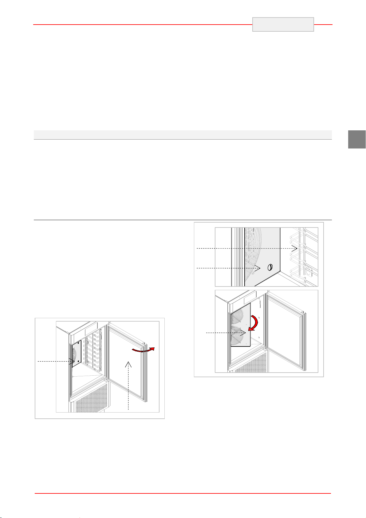
To access the evaporator proceed as follows:
1. Open the door (A) of the appliance.
2. Loosen the two screws (B) on the right of the
deflector.
3. Remove the runners (C):
4. Turn the deflector (D) to the left
B
A
C
B
D
17
Page 19
Cleaning the condenser
Clean the condenser periodically.
ENGLISH
! As the fins of the condenser are very sharp,
always wear protective gloves for the next
phases. Use protective masks and glasses in the
presence of dust.
C
GB
Whenever the condenser has a deposit of
dust in correspondence with the fins, this can be
removed using a suction device or with a brush
applied, using a vertical movement along the
direction of the fins.
! No other instruments must be used, which
may deform the fins and therefore the efficiency of
the appliance.
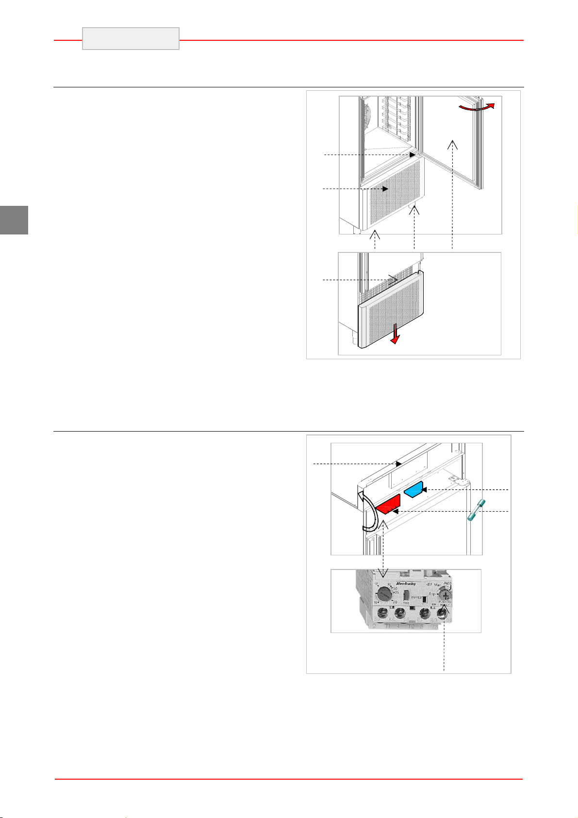
To clean, proceed as follows:
1. Open the door (A) of the appliance.
2. Remove the lower panel (B) from the
technical compartment: to do this, remove
the screw fasteners (C).
3. It is now possible to clean the finned part
of the condenser (D) using suitable tools
and protection devices.
4. After cleaning, close the control panel and
fix it with the screws removed beforehand.
Fuse replacement and thermal relay rearm
The fuses (A) and the thermal relay (B) are
in the upper part of the blast chiller. To access
these just open the control panel (C) by loosening
the two screws (D) positioned in the lower part of
the control panel and rotating it upwards. After
opening, make sure that it does not fall back
down.
B
C
D
C
C A
A
B
Rearm the heat relay using
the grey button
18
D
Page 20

7. TROUBLESHOOTING
The information shown below aims to help with
the identification and correction of any anomalies
and malfunctions which could occur during use.
Some of these problems can be resolved by the
Problem Causes Solutions
ENGLISH
user. For the others, precise skill is required and
they must therefore only be carried out by
qualified staff.
Check the power supply cable.
The refrigerator unit does not start
The refrigerator unit functions
continuously, cooling insufficiently
Problem Causes Solutions
No voltage
Check the correct connection of the
Other causes
Room too hot Air the environment
Dirty condenser clean the condenser
Insufficient door sealing check the gaskets
Insufficient quantity of
refrigerant gas
Condenser fan at a standstill
Evaporator fan standstill
If the problem persists,
contact the after-sales centre.
Contact the after-sales
Contact the after-sales
Contact the after-sales
Check fuses.
appliance.
centre.
centre.
centre.
GB
The refrigerator unit does not stop
Presence of ice inside the
evaporator
Appliance noise Persistent vibrations
Probe faulty
Circuit board fault
19
Contact the after-sales
centre.
Contact the after-sales
centre.
Carry out a defrosting cycle possibly
with the door open.
If the problem persists,
contact the after-sales centre.
check there is no contact between
the appliance and other objects
inside or outside
Page 21

ENGLISH
7.1. Faults Display
Problem
Causes Solutions
GB
Pr1
Pr3
Pr2
rtc
Pf
"Pr1" flashes on the display
and the buzzer emits an
intermittent noise
(compartment probe error)
"Pr3" flashes on the display
and the buzzer emits an
intermittent noise
(evaporator probe error)
"Pr2" flashes on the display
and the buzzer emits an
intermittent noise
(needle probe error)
“rtc” flashes on the
display
“Pf" flashes on the display and
the buzzer emits an
intermittent noise
(electrical power supply
failure alarm)
The type of probe is
incorrect.
The probe is faulty.
The probe – circuit board
connection is incorrect.
The temperature detected
by the probe is out of the
limits accepted by the
compartment probe in use
Clock error
There has been a power failure.
Contact the after-
sales centre.
Check that the
compartment probe is
the PTC type.
Check the integrity of the
compartment probe.
Check correctness of the
instrument - probe
connection.
Check that the
temperature in proximity
of the compartment
probe is not out of the
accepted limits
Set date and correct time
again.
Check the electrical
system.
Contact the after-sales
service if the problem
persists.
HP
"HP" flashes on the display
and the buzzer emits an
intermittent noise
high pressure
Compressor Circuit
Breaker alarm
evaporator fan deflector
The pressure detected by
the maximum pressure
switch is higher than the
limit value.
The evaporator fan deflector
has been opened.
The absorption of the
compressor has exceeded
the envisioned maximum
limit.
Air the environment.
Clean the condenser
Close the evaporator fan
deflector.
Check that the fans
function correctly.
If the problem
persists, contact the after-
sales centre
20
Page 22
8. INSTALLATION
8.1. Packaging And Unpacking
Handle and install the appliance respecting the
information provided by the manufacturer, shown
directly on the packaging, on the appliance and in
this manual.
The lifting and transportation system of the
packaged product envisions the use of a fork-lift
truck or a pallet stacker. When using these,
particular attention must be paid to balancing the
weight in order to prevent the risk of overturning
(avoid excessive tilting!).
! ATTENTION: When inserting the lifting
device, pay attention to the power supply cable
and the position of the feet.
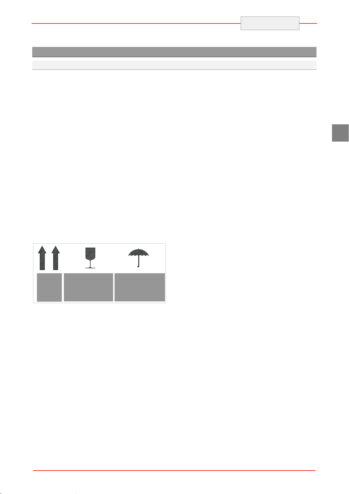
The packaging is made of cardboard and the
pallet of wood. A series of symbols is printed on
the cardboard packaging which highlights, in
accordance with international standards, the
provisions to which the appliances are subjected
during loading, unloading, transport and storage.
ENGLISH
On delivery, check that the packaging is intact and
has not undergone any damage during
transportation.
The transportation company must be notified of
any damage immediately.
The appliance must be unpacked as soon as
possible to check that it is intact and undamaged.
Do not cut the cardboard with sharp tools so as
not to damage to the steel panels underneath.
Pull the cardboard packaging upwards.
After having unpacked the appliance, check that
the features correspond to those requested in the
order;
Contact the dealer immediately if there are any
anomalies.
! Packaging elements (nylon bags,
polystyrene foam, staples …) must not be left
within reach of children.
Remove the protective PVC film from the internal
and external walls, avoiding the use of metal
tools.
GB
TOP
FRAGILE
HANDLE
WITH CARE
DO NOT EXPOSE
TO HUMIDITY
21
Page 23

GB
ENGLISH
8.2. Installation
All the installation phases must be considered,
from the moment of creation of the general plan.
The installation area must be equipped with all
power supply and production residue drainage
connections and must be suitably lit and respect
current laws regarding hygiene and sanitary
requirements.
The performance of the appliance is
guaranteed with a room temperature of 32°C. A
higher temperature can compromise its
performance and, in more serious cases, cause
the appliance’s protections to start up.
Therefore, consider the most critical room
conditions that can be reached in that position
before making a choice.
Level the appliance by acting on the individual
feet.
! This appliance can only be installed and
operate in rooms which are permanently
ventilated, in order to guarantee correct operation.
8.3. Electric Power Supply Connection
Connection must be carried out by authorised and
qualified staff, respecting the current laws
regarding the subject and using appropriate
prescribed material.
Before connecting the appliance to the
electric mains, check that the voltage and the
frequency correspond to the data stated on the
registration plate applied on the rear of the
appliance.
The appliance is supplied with an operating
voltage of 400V 3+N~ 50Hz. On request, it is
Connect and leave for a certain period of
time (at least 2 hours) before checking
functioning. During transport it is probable that the
compressor lubricant oil has entered the
refrigerant circuit blocking the capillary: as a
consequence the appliance will function for a
certain period of time without producing cold until
the oil has returned to the compressor.
! ATTENTION: the appliance requires the
minimum functioning spaces, as shown in the
attachments.
The defrosting water and the water that forms at
the bottom of the refrigerating compartment
during operation or during periodical internal
cleaning must be drained through a prearranged
hose with a minimum diameter 3/4” connected to
the hose at the bottom of the chiller.
A drain trap should also be guaranteed. The drain
must be in compliance with Standards in force.
possible to have appliances with different
voltages.
! Before connection, ensure the presence of a
relevant differential switch with adequate power in
the mains power supply, upstream from the
appliance, in order to protect the appliance from
overloads or short circuits
22
Page 24
8.4. Inspection
The appliance is delivered in conditions such that
it can be started-up by the user.
This functionality is guaranteed by passing the
tests (electric inspection - functional inspection,
appearance inspection) and relative certification
through the specific attachments.
At least the following should be checked after
installation:
Check the electric connections.
Check the functionality and efficiency of
drains.
8.5. Programming the settings
It is only possible to program the configuration
settings in STANDBY mode.
Make sure the keyboard is not locked.
ENGLISH
Check that there are no tools or materials
left in the appliance that could jeopardise
its functionality or even damage the
machine.
Have the appliance perform at least one
complete chill blasting/shock freezing
cycle
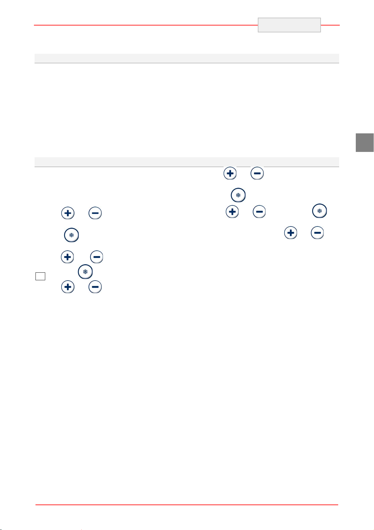
With the
the list of parameters
Press the
and keys it is possible to scan
key to change the parameter
GB
Hold the
the screen will display the letters "PA".
Press the
to access the parameters.
With the
-19 : press the
Hold the and keys down for 4 seconds:
the screen will display the letters "SP" (first
available parameter).
and keys down for 4 seconds:
key: the password will be required
and keys enter the password
key to confirm.
using the
to confirm the change.
To exit the procedure hold the
down for 4 seconds.
and keys: press the key
and keys
To make some of the parameters
operational it is necessary to turn the appliance off
and on again.
23
Page 25

GB
ENGLISH
9. DISPOSAL OF THE APPLIANCE
This appliance is marked in compliance with
the 2002/96/EC European Directive, WASTE
ELECTRICAL AND ELECTRONIC EQUIPMENT
(WEEE).
! By assuring that this product is disposed of
correctly, the user contributes to preventing the
potential negative consequences on the
environment and health.
that this product must not be treated as domestic
waste but must be taken to suitable collection
points for the recycling of electric and electronic
appliances.
Dispose of it following local regulations regarding
waste disposal.
For further information regarding the treatment,
recovery and recycling of this product, contact the
relevant local office, the domestic waste collection
service or the shop where the product was
purchased.
The
or on the accompanying documentation indicates
symbol found on the product
10. REFRIGERANT TECHNICAL CARD
The refrigerant used in the machine is R452A
fluid. Below find the components of the fluid:
HFC-125 59%
HFC-1234yf 30%
HFC-32 11%
IDENTIFICATION OF DANGERS
The rapid evaporation of the liquid can cause
freezing. The inhalation of high concentrations
of vapour can cause irregular heartbeat, short
term narcotic effects (including vertigo, headache
and mental confusion), fainting and death.
Effects to the eyes: Freezing or cold bu rns
caused by contact with the liquid.
Effects on the skin: Freezing or cold burns
caused by contact with the liquid.
Effects of ingestion. Ingestion is not
considered a means of exposure
FIRST AID
Eyes: In the case of contact, wash the eye well
using a large amount of water for at least 15
minutes. Consult a doctor.
Effects on the skin: Wash with water for at least
15 minutes after excessive contact. If necessary,
cure freezing by gently warming the area in
question. Consult a doctor in the case of irritation.
Ingestion: Ingestion is not considered a means of
exposure.
Inhalation: If large concentrations are inhaled, go
into the open air. Keep the person calm. If the
person cannot breath, perform artificial
respiration. If respiration is difficult, apply oxygen.
Consult a doctor.
24
Page 26

PERFECTION IN COOKING AND MORE...
RETIGO s.r.o.
Láň 2310
756 61 Rožnov pod Radhoštěm
Email: [email protected]
Tel.: +420 571 665 511
www.retigo.com
 Loading...