

Page 1

Page 2
Instruction Manual
RT95 UHF/VHF Two Way Radio
RT95
http://radioaficion.com/hamfiles/
Page 3

CONTENTS
1.FUNCTIONS & FEATURES ........................................................................... 1
2.ACCESSORIES ............................................................................................. 2
3.INITIAL INSTALLATION ................................................................................ 3
4.GETTING ACQUAINTED ............................................................................... 8
5.WORKING MODE ........................................................................................ 11
6.BASIC OPERATIONS .................................................................................. 12
7.FUNCTION MENU ....................................................................................... 16
8.CHANNEL MENU ........................................................................................ 21
9.KEYPAD MENU SETUP .............................................................................. 25
10.DTMF SETTTING ....................................................................................... 26
11.PROGRAMMING SOFTWARE .................................................................. 27
12.MAINTENANCE ......................................................................................... 28
13.SPECIFICATIONS ...................................................................................... 29
14.ATTACHED CHART ...................................................................................30
Page 4

1
RT95 UHF/VHF Two Way Radio
1. FUNCTIONS & FEATURES
♦ Adopt superior quality material, better technology and high quality radiator to
ensure stable and durable operation;
♦ 180 degree rotatable TFT LCD display;
♦ Full alloy body for heat radiation;
♦ Amateur mode and professional mode for different operation requirement;
♦ Distribute buttons reasonably, convenient for operation;
♦ Separate band width setting for each single channel, Wide 25K, Middle band
20K, Narrow band 12.5K;
♦ 200 programmable memory channels, identied by editing name;
♦ Separate CTCSS, DCS, DTMF, 5Tone setting for each single channel,
rejecting extra calling from other radios;
♦ Various scan functions including CTCSS/DCS Scan function;
♦ Smart menu control and PC programming control;
♦ Voltage level protection;
♦ LCD brightless control;
♦ Automatic power on function;
♦ Main unit and microphone key lock function;
♦ 5Tone signaling for data transfer,alarm, all call, ANI, remote kill, remote
waken.
♦ DTMF-ANI or 5Tone-ANI for automatical calling recognition;
♦ Scrambler(Optional).
MT500 Mobile Radio has nice housing, stoutness & stability, advanced and
reliable functions, perfect & valuable. This amateur mobile radio especially designs
for drivers and it pursues philosophy of innovation and practicality. More functions as
follows:
Page 5
2
RT95 UHF/VHF Two Way Radio
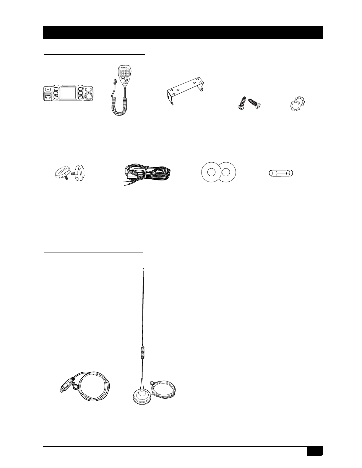
2. ACCESSORIES
PC cable
Car Antenna
Transceiver
Screws
Microphone
Pads
Adjusting screws
DC Power Cable
with Fuse Holder
Mobile Bracket
non-slip mat Fuse(10A 250V)
MIC
P1
FUNC
P4
P5
P6
P2
P3
2.1 Standard Accessories
2.2 Optional Accessories
Page 6
3
RT95 UHF/VHF Two Way Radio
3. INITIAL INSTALLATION
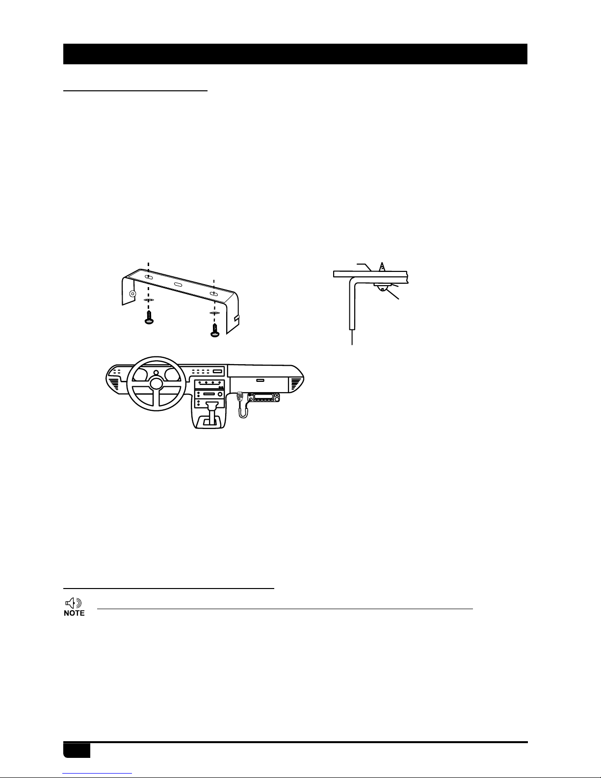
To install the transceiver, select a safe, convenient location inside your vehicle that
minimizes danger to your passengers and yourself while the vehicle is in motion. Consider
installing the unit at an appropriate position so that knees or legs will not strike it during
sudden braking of your vehicle. Try to pick a well ventilated location that is shielded from
direct sunlight.
1.Install the mounting bracket in the vehicle using the supplied selftapping screws (2pcs)
and at washers (2pcs)
2.Position the transceiver, then insert and tighten the supplied hexagon SEMS screws.
♦ Double check that all screws are tightened to prevent vehicle vibration from loosening
the bracket or transceiver.
Car body
Washer (M5)
Tapping screw
(M5x20mm)
Mounting bracket
3.1 Mobile Installation
3.2 DC Power Cable Connection
»
Locate the power input connector as close to the transceiver as possible.
3.2.1 Mobile Operation
The vehicle battery must have a nominal rating of 12V. Never connect the transceiver to
a 24V battery. Be sure to use a 12V vehicle battery that has sufcient current capacity. If
the current to the transceiver is insufcient, the display may darken during transmission,
or transmitting output power may drop excessively.
Page 7
4
RT95 UHF/VHF Two Way Radio
3.2.2 Fixed Station Operation
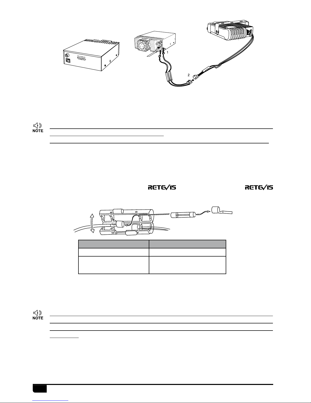
In order to use this transceiver for xed station operation, you will need a separate 13.8V
DC power supply,Please
contact local dealer to require.
The recommended current capacity of your power supply is 12A.
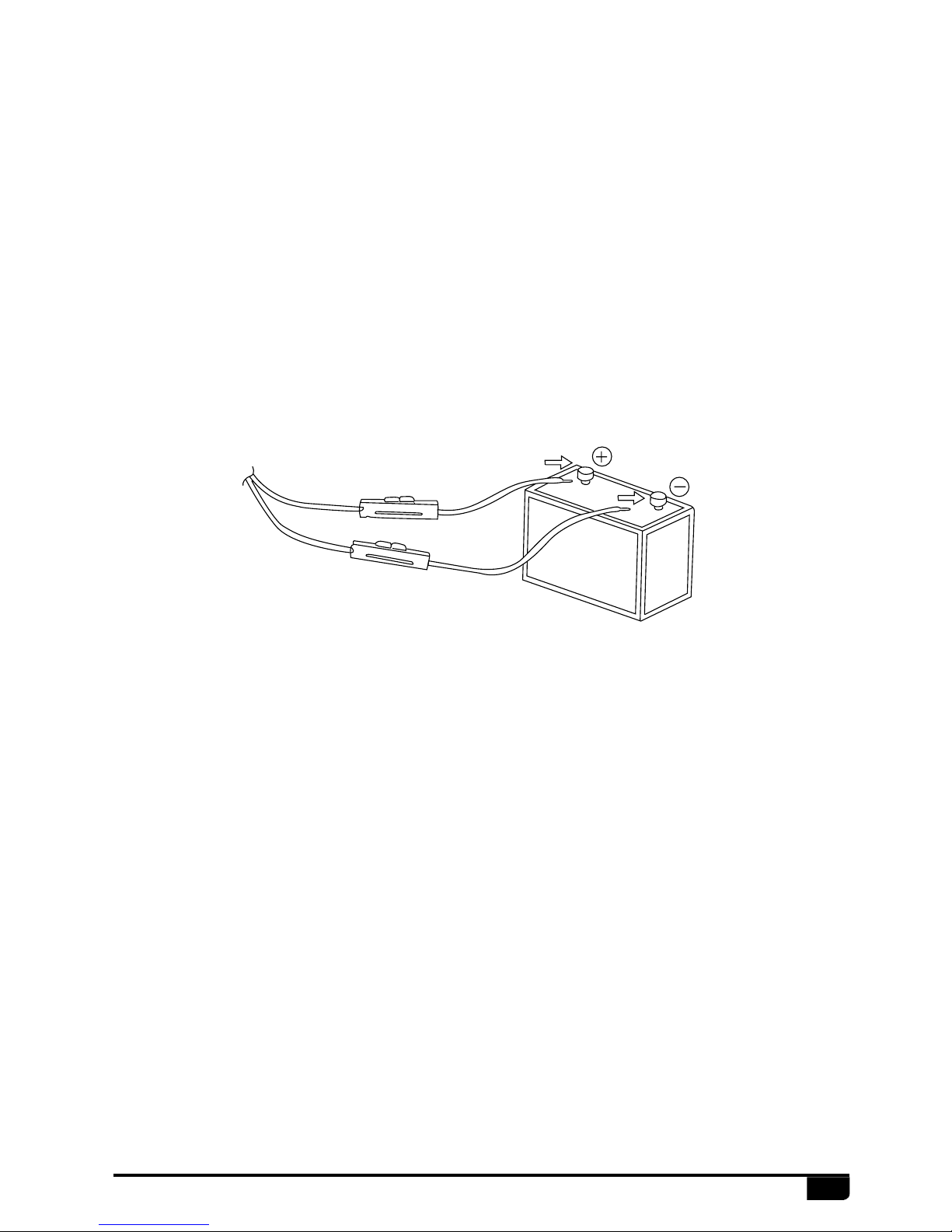
1.Connect the DC power cable to the regulated DC power supply and ensure that the
polarities are correct. (Red: positive, Black: negative).
♦ Do not directly connect the transceiver to an AC outlet.
♦ Use the supplied DC power cable to connect the transceiver to a regulated power
supply.
♦ Do not substitute a cable with smaller gauge wires
.
1.Route the DC power cable supplied with the transceiver directly to the vehicle's battery
terminals using the shortest path from the transceiver.
♦ We recommend you do not use the cigarette lighter socket as some cigarette lighter
sockets introduce an unacceptable voltage drop.
♦ The entire length of the cable must be dressed so it is isolated from heat, moisture,
and the engine secondary (high voltage) ignition system/ cables.
2. After installing cable, in order to avoid the risk of damp, please use heat-resistant tap to
tie together with fuse box. Don't forget to reinforce whole cable.
3.In order to avoid the risk of short circuit, please cut down connection with negative (-) of
battery, then connect with radio.
4.Confirm the correct polarity of the connections, then attach the power cable to the
battery terminals; red connects to the positive (+) terminal and black connects to the
negative (-) terminal.
♦ Use the full length of the cable without cutting off excess even if the cable is longer
than required. In particular, never remove the fuse holders from the cable.
5. Reconnect any wiring removed from the negative terminal.
6. Connect the DC power cable to the transceiver's power supply connector.
♦ Press the connectors rmly together until the locking tab clicks.
Red
Black
Page 8
5
RT95 UHF/VHF Two Way Radio
»
Before connecting the DC power to the transceiver, be sure to switch the
transceiver and the DC power supply OFF.
»
Do not plug the DC power supply into an AC outlet until you make all connections.
»
If you use the transceiver for a long period when the vehicle battery is not fully
charged, or when the engine is OFF, the battery may become discharged, and will
not have sufcient reserves to start the vehicle. Avoid using the transceiver in these
conditions.
3.2.3 Replacing Fuses
If the fuse blows, determine the cause, then correct the problem. After the problem is
resolved, replace the fuse. If newly installed fuses continue to blow, disconnect the
power cable and contact your authorized dealer or an authorized
servicecenter for assistance.
Only use fuses of the specified type and rating, otherwise the transceiver could be
damaged.
2.Connect the transceiver's DC power connector to the connector on the DC power cable.
♦ Press the connectors rmly together until the locking tab clicks.
Red
Black
Regulated power supply
DC power cable with fuse holder
Regulated
power supply
Fuse Location Fuse Current Rating
Transceiver 10A
Supplied Accessory DC
power cable
10A
E
X
T
S
P
A
N
T
Page 9
6
3.3 Antenna Connection
3.4 Accessories Connections
Before operating, install an efcient, well-tuned antenna. The success of your installation
will depend largely on the type of antenna and its correct installation. The transceiver can
give excellent results if the antenna system and its installation are given careful attention.
Use a 50Ω impedance antenna and low-loss coaxial feed-line that has a characteristic
impedance of 50Ω, to match the transceiver input impedance. Coupling the antenna to the
transceiver via feed-lines having an impedance other than 50Ω reduces the efciency of
the antenna system and can cause interference to nearby broadcast television receivers,
radio receivers, and other electronic equipment.
3.4.1 External Speaker
If you plan to use an external speaker, choose a speaker with an impedance of 8Ω. The
external speaker jack accepts a 3.5mm (1/8") mono (2-conductor) plug.
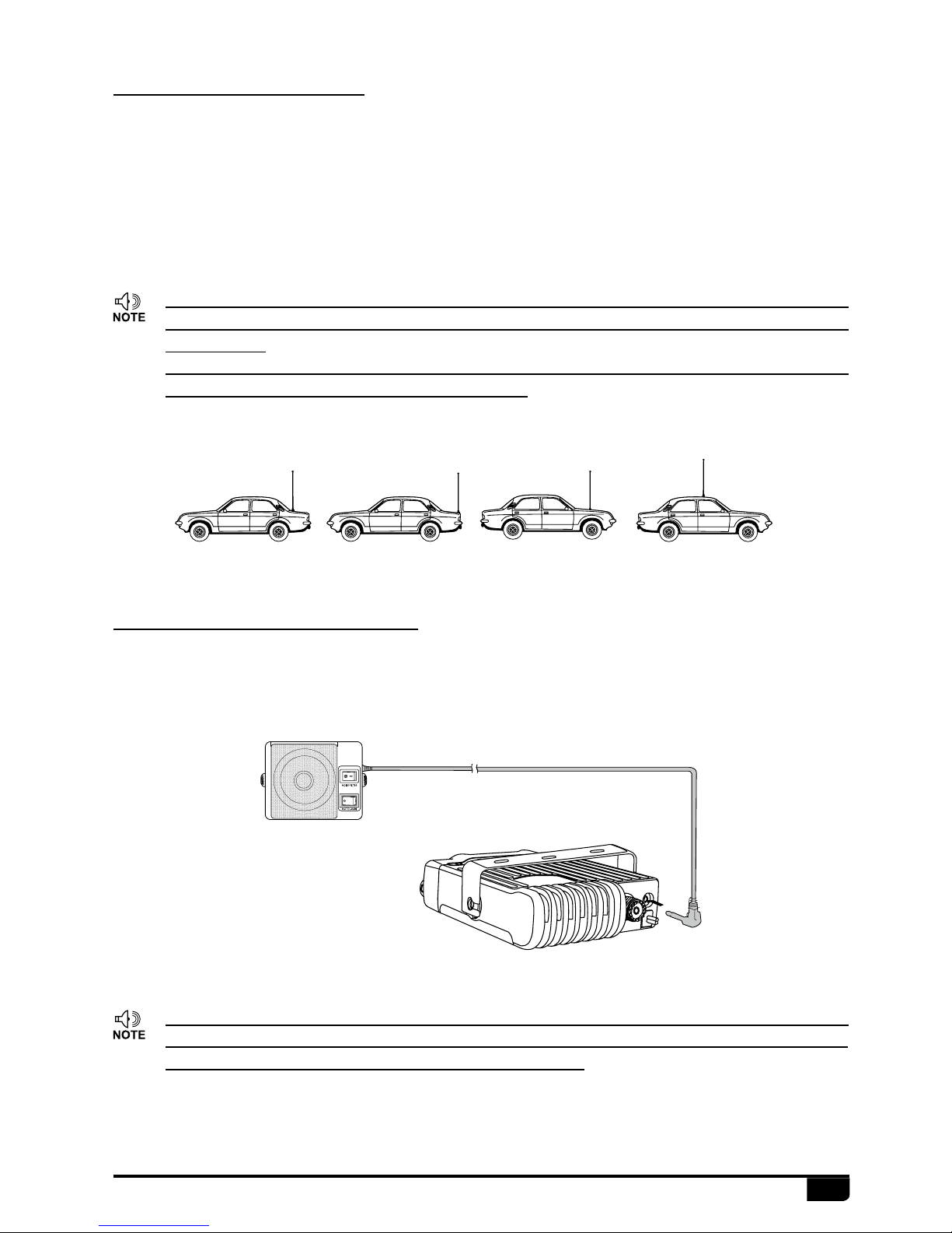
The possible locations of antenna on a car are shown as following:
»
Transmitting without first connecting an antenna or other matched load may
damage the transceiver. Always connect the antenna to the transceiver before
transmitting.
»
All xed stations should be equipped with a lightning arrester to reduce the risk of
re, electric shock, and transceiver damage.
»
External speaker adopt double port BTL, please care about the connecting way.
The speaker can not connect with the ground, otherwise the speaker will be fault.
The wrong connecting way as the following picture.
E
X
T
S
P
A
N
T
RT95 UHF/VHF Two Way Radio
Page 10
7
3.4.2 Microphone
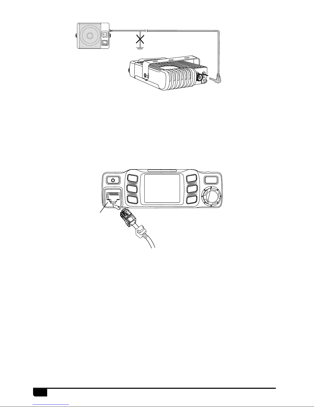
For voice communications, connect a microphone equipped with an 8-pin modular plug
into the modular socket on the front of the main unit. Press irmly on the plug until the
locking tab clicks.
Ground
Error
Microphone
connector
E
X
T
S
P
A
N
T
MIC
P1 P4
FUNC
P5
P6
P2
P3
http://radioaficion.com/hamfiles/
Page 11
8
RT95 UHF/VHF Two Way Radio
4. GETTING ACQUAINTED
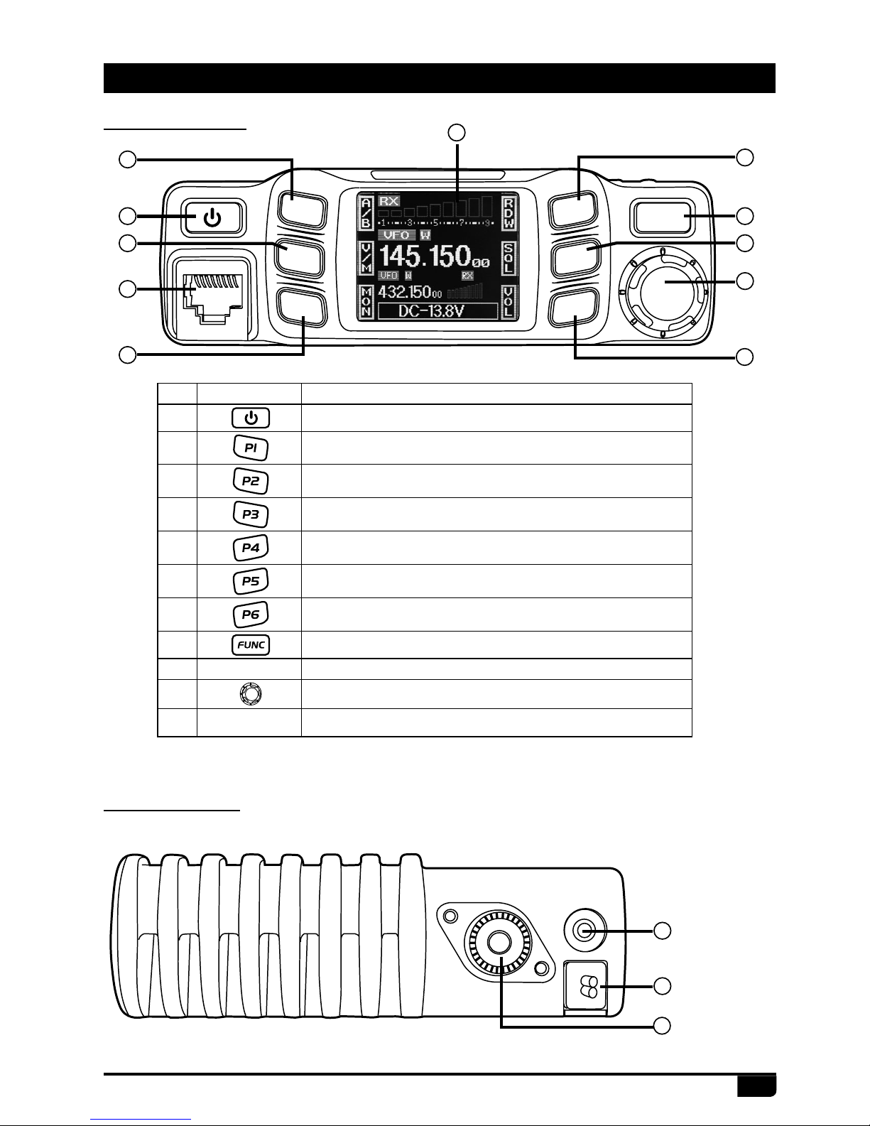
4.1 Front panel
4.2 Rear panel
NO. Key Functions
1
Power On/Off/Mute
2
Self dene key
3
Self dene key
4 Self dene key
5 Self dene key
6 Self dene key
7 Self dene key
8
Function key/ function group key
9 MIC Microphone Jack
10 Channel switch/Push button/Key lock
11 LCD display Display channel/frequency/function setting
2
5
1
11
9
8
3
6
10
4
7
MIC
P1
FUNC
P4
P5
P6
P2
P3
2
3
1
ANT EXT SP
Page 12
9
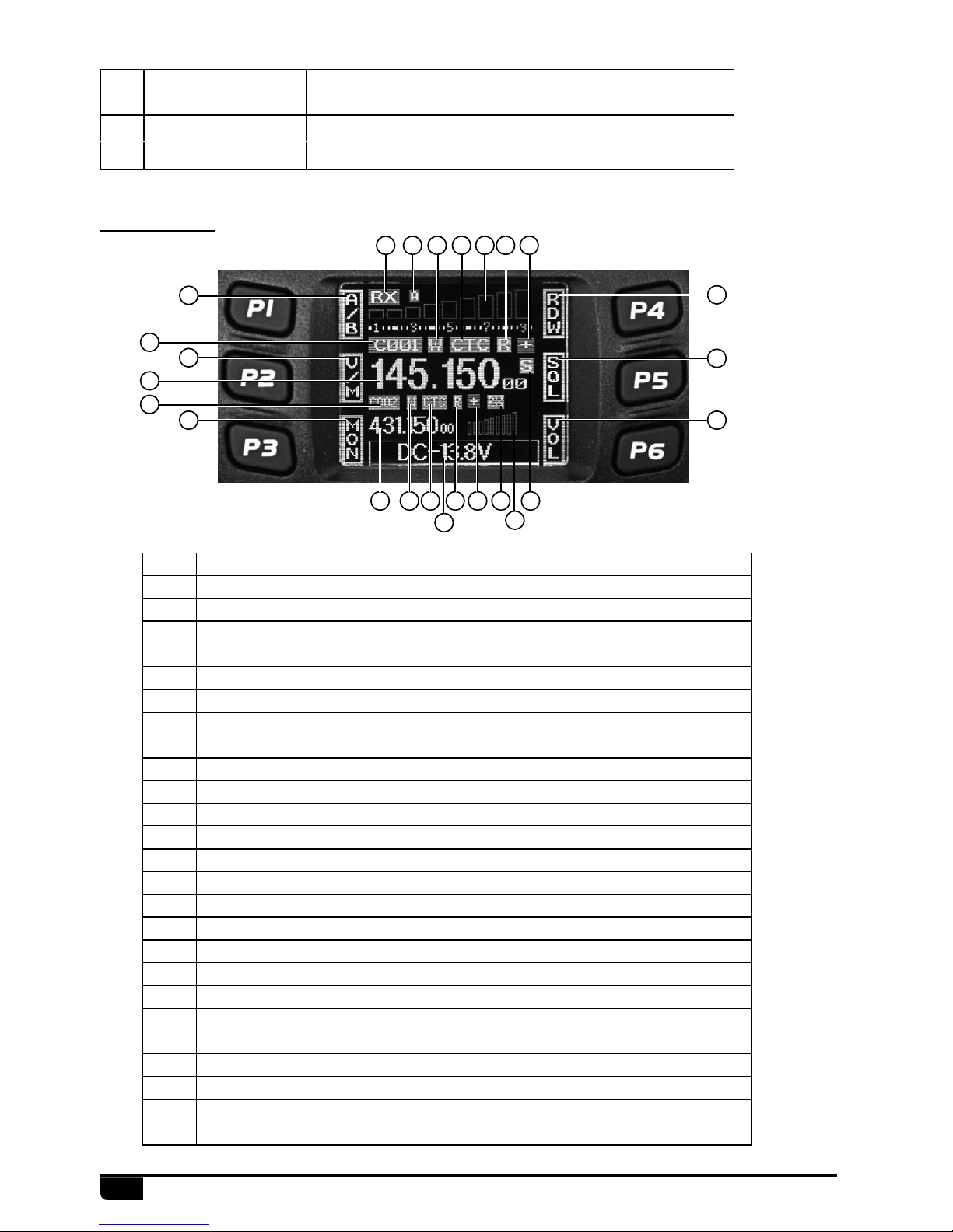
4.3 Display
NO. Key Functions
1 Antenna connector Connect a 50 ohm antenna
2 Ex-Speaker Jack Connect external speaker
3 Power cable Connect a standard DC power cable
NO. Functions
1 Displays the self dene function when press P1
2 Displays the self dene function when press P2
3 Displays the self dene function when press P3
4 Displays the self dene function when press P4
5 Displays the self dene function when press P5
6 Displays the self dene function when press P6
7 Displays the main channel TX or RX status
8 Displays when Automatic power off function is on
9 Displays the main channel eld strength
10 Displays main channel number in channel mode
11 Displays when set band width for main channel
12 Displays when main channel set CTCSS/DCS
13 Displays when main channel reverse function is on
14 Displays when main channel offset function is on
15 Displays when main channel is in scan list
16 Displays main channel frequency or name
17 Displays sub channel number in channel mode
18 Displays when setting band width for sub channel
19 Displays when current sub channel set CTCSS/DCS
20 Displays when sub channel reverse function is ON
21 Displays when sub channel offset function is ON
22 Displays when sub channel receive a signal
23 Display sub channel frequency or name
24 Displays signal strength of sub channel
25 Display voltage and menu setting
1
7 8 911
12 13 14
1518 19 20
21 2223
24
25
10
2
16
17
3
6
5
4
Page 13
10
RT95 UHF/VHF Two Way Radio
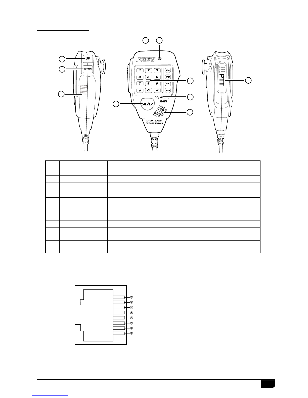
4.4 Microphone
1
2
10
3
5
6
9
7 8
4
NO. Key Functions
1 UP Increase frequency, channel number or setting value
2 DOWN Decrease frequency, channel number or setting value
3 PTT Press the PTT (Push-TO-Talk) key to transmit
4 Number Key Input VFO frequency or DTMF dial out etc.
5 A/B band Choose left band or right band as Main band
6 Band indicator The indicator light on for Main band
7 TX/RX indicator Light green while receiving, Light red while transmitting
8 MIC Speak here during transmission
9 Speaker
When shut the speaker in the base, you can hear the calling by
this speaker
10 Lock UP/DOWN
When this key is in up position, It is unlock UP/DOWN key, when
this key is in down poisition, UP/DOWN key will be locked
MIC Connector Diagram(in the front view of connector)
Key Pad Serial Data
+5V
DOWN
UP
MIC GND
MIC
PTT
GND
Page 14
11
RT95 UHF/VHF Two Way Radio
According to practical application, you can set the radio works as Amateur Transceiver
mode or Professional Transceiver mode. There are also 2 levels operation menu to set
functions as you need. It is easy and convenient. FUNC MENU is for set background
function, CHAN MENU for set channel function, MINI KEY menu for set self dene key,
HAND KEY for set self mic dene key.
1.Working Mode:
A. By programming software: In PC software's "General Setting" menu, choose "Display
Mode" to select Amateur Transceiver mode or Professional Transceiver mode.
B. By manual setup: Please refer to "Display Mode" in Page 16.
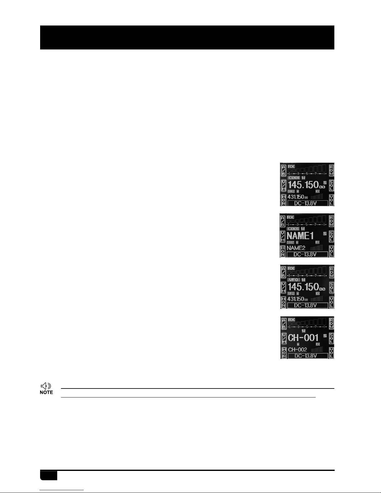
2.Amateur Transceiver Mode:
Except setting as "CH" mode, others considered as Amateur transceiver
mode. Under this mode, press V/M matched PX key to switch between
Channel mode and VFO mode.
A. Frequency+Channel mode: When set display as "FRQ", it enters into
Frequency+Channel mode, new setting of channel operation and
shortcut operation can be temporarily used by user. Once the radio
is turned off or switched to anothe channel, the temporary setting will
be erased and back to initial settings.(As pic 1)
B. Channel+Name Tag Mode: When set display as "NM",it enters
into Channel +Name Tag mode. At this mode, it will display
corresponding channel name when the current channel is edited with
name. Otherwise, it will display frequency + channel. Its operations
are same as frequency + channel mode.(As pic 2)
C. VFO Mode(Frequency mode): This mode shows only frequency on
the display. Shortcut operation and Channel setting will be changed
& stored as the latest value permanently. Once the radio is turned off
or changed to new VFO frequency, the latest setting is remained until
next change.(As pic 3)
3. Professional Transceiver Mode:
When set display mode as "CH" , it enters into Professional Transceiver
mode. If there is corresponding name for current channel , the LCD
will display current channel name otherwise it shows current channel
number. (As Pic 4)
5. WORKING MODE
(AMATEUR TRANSCEIVER OR PROFESSIONAL TRANSCEIVER)
4.Under any mode, the FUNC MENU setting can be changed and saved.
»
If transceiver programmed as professional transceiver mode and locked, you can't
return to amateur transceiver mode by manual operation from general setting.
(pic1)
(pic2)
(pic3)
(pic4)
Page 15
12
RT95 UHF/VHF Two Way Radio
6. BASIC OPERATIONS
6.1 Switching the Power On/Off
6.2 Adjusting the Volume
6.3 Adjusting Frequency
6.4 Adjust Channel
1. In standby mode, short press the [PX] key programmed as VOL control, the LCD
display "VOL:XX", then turn the channel switch to adjust volume level.
2. In standby mode, short press
to mute the speaker, the LCD display "AUDIO:MT",
short press it again to return last volume level.
1. Power On: in power off state press
, the LCD displays " RETEVIS " then will
displays current frequency or channel.
2. Power Off: in power on state, press
for 2 seconds, the LCD displays "CLOSING",
then the LCD display disappears.
1. By channel knob: In VFO mode, turn channel knob can adjust frequency, push channel
knob, the matching charactor will ash, then turn channel knob to adjust the frequency
by step size 1K, 10K, 100K, 1Mz or 10MHz.
1. Adjust channel by channel switch: In channel mode, turn channel knob to adjust the
channel, the [UP]/[DOWN] key in the microphone can also adjust the main channel.
»
During communication, volume level can be adjusted more accurate.
»
The microphone [UP]/[DOWN] key can also adjust the frequency, each press
move one step size. hold the [DOWN] key can decrease one step size. if the
channel knob is programmed as VOL function, users need press the PX key which
programmed as FRQ function, when the LCD displays "VFO FREQ", turn channel
knob to adjust frequency.
»
If there is an empty channel, the radio will jump over it to next channel. If the
channel knob is programmed as VOL function, users need press the PX key which
programmed as CH function, when the LCD displays "CH XX ", turn channel knob
to adjust channel.
2. By number key: In VFO mode, you can input wanted frequency by the microphone
number key. For example if want 145.125Mhz, just press key 1, 4, 5, 1, 2, 5, if want
145Mhz, just press 1, 4, 5. The input is invalid if the frequency is over range.
2. By number key: In CH mode, you can input wanted channel by the microphone input
3 numbers (001-200) , 001 stands for channel 1, 200 stands for channel 200. if input
channel is an empty channel, the radio will report error and return to last channel.
Page 16
13
RT95 UHF/VHF Two Way Radio
6.5 Receiving
6.6 Transmitting
6.7 Switch between Main Channel and Sub Channel
6.8 Switch between VFO and Channel Mode
6.9 Channel Edit
When the channel you are operating being called, the screen shows red RX and field
strength in this way you can hear the calling.
Hold [PTT] and speak into microphone. the radio start transmit, the screen shows red
TX and eld strength. Hold the microphone approximately 2.5-5.0cm from your lips and
speak to microphone in your normal speaking voice to get best timbre.
This radio work by single channel dual watch , in standby, the frequency in the upper
side is main channel and down side is sub channel, the transmit is available only on main
channel.
1. Short press [FUNC] to switch function group, choose the [PX] key defined as A/B
function.
2. Short press [PX] key dened as A/B function, then repeatedly press this key or turn
channel knob to switch main channel and sub channel, the LCD displays Main:XX.
3. Hold [PUSH] or [FUNC] key to store and exit, or wait 10 seconds the radio will store the
setting and exit.
1. Short press [FUNC] to switch function group, choose the [PX] key defined as V/M
function.
2. Short press [PX] key defined as V/M function, then repeat press this key or turn
channel knob to switch main channel and sub channel, the LCD displays V/M:XX.
3. Hold [PUSH] or [FUNC] key to store and exit, or wait 10 seconds the radio will store the
setting and exit.
1. In VFO mode, turn channel knob or the [UP]/[DOWN] key in microphone to adjust
frequency.
2. Short press [FUNC] to switch function group, choose the [PX] key defined as CDT
function. Press [PX] key defined as CDT function to set CTCSS/DCS code. turn
channel knob or the [UP]/[DOWN] key in microphone to choose CTCSS/DCS code.
3. Long press [FUNC] key to enter channel setting menu, to choose wanted setting.
4. Short press [FUNC] key to switch function group, hold the [PX] key defined as V/M
function until the channel number ashes, if the channel number is red means current
channel is valid, if the channel number is green, means current channel is empty.
5. Turn the channel knob or microphone [UP]/[DOWN] key to choose the channel number
to be stored.
6. Hold the [PX] key dened as V/M function to conrm and store the channel, the channel
number stop ash and radio emits a beep sound, the channel is stored successfully.
»
When the RX icon and eld strength ashes, but can not hear the calling, it means
current channel receive a matching carrier but unmatching signaling. Refer to
CTCSS/ DCS CODE or Optional Signaling setup in Page 14).
»
Only available transmit on main channel.
Page 17
14
RT95 UHF/VHF Two Way Radio
6.10 Channel Delete
6.11 CTCSS/DCS Encode and Decode Setup
6.12 CTCSS Scan
6.13 DCS Scan
1. In channel mode, turn the channel knob or microphone [UP]/[DOWN] key to choose an
unwanted channel.
2. Short press [FUNC] key to switch function group, choose the [PX] key dened as V/
M function, press this key together with [FUNC] key for 2 seconds, current channel is
deleted and automatical jump to next channel.
1. Short press [FUNC] to switch function group, choose the [PX] key defined as CDT
function.
2. Short press PX dened as CDT function, then repeatedly short press this key set the
currently channel if use CTCSS/DCS encode and decode.
3. When the LCD displays: RCDT:XXX, turn channel knob or press microphone [UP]/
[DOWN] key to choose if add CTCSS/DCS decode signaling to current channel. Press
[PUSH] button then turn channel knob or press microphone [UP]/[DOWN] key to
choose wanted CTCSS/DCS decode signaling.
4. When the LCD displays: TCDT:XXX, turn channel knob or press microphone [UP]/
[DOWN] key to choose if add CTCSS/DCS encode signaling to current channel. Press
[PUSH] button then turn channel knob or press microphone [UP]/[DOWN] key to
choose wanted CTCSS/DCS encode signaling.
5. CTCSS: 62.5-254.1Hz plus one self dene group. total 52 groups.
DCS: 000N-777I total1024 groups.
N is positive code, I is inverse code.
Press FUNC key can choose positive or inverse code.
6. Hold [PUSH] or [FUNC] key to store and exit, or wait 10 seconds the radio will
automatically store the setting and exit.
In channel or VFO mode, short press [FUNC] to switch function group, choose the [PX]
key dened as CDT function. short press this key to enter CTCSS code setting. when
the LCD displays CTC, long press this key to enter CTCSS scan. turn channel knob or
press microphone [UP]/[DOWN] key can change scan direction. Once nding a matching
CTCSS signaling, it will stop 5 seconds then scan again, short press any key to exit
CTCSS scan.
In channel or VFO mode, short press [FUNC] to switch function group, choose the [PX]
key dened as CDT function. short press this key to enter DCS code setting. When the
LCD displays DCS, long press this key to enter DCS scan, turn channel knob or press
microphone [UP]/[DOWN] key can change scan direction. Once nding a matching DCS
signaling, it will stop 5 seconds then scan again, press any key to exit DCS scan.
»
Under channel mode,this operation can be temporarily used by user. Once the
radio is turned off or switched to another channel, the temporary setting will be
erased. If the channel setting programmed for valid, the temporary setting will keep
valid until next change, turn off radio or switch to another channel, the temporary
setting will not changed.
Page 18
15
RT95 UHF/VHF Two Way Radio
6.14 Frequency/Channel Scan
6.15 Scan Skip
6.16 Squelch off/ Squelch off Momentary
6.17 KEYPAD LOCKOUT
Frequency Scan
In frequency (VFO) mode, this function is designed to monitor signal of all frequency
points under each step size.
1. In VFO mode, short press [FUNC] key to switch function group, choose the [PX] key
dened as SCN function.
2. Short press the [PX] key defined as SCN function to start frequency scan, the LCD
displays "S".
3. Turn channel knob or press microphone [UP]/[DOWN] key can change scan direction.
4. Turn channel knob or press any key except microphone [UP]/[DOWN] key to exit.
In channel mode, press [FUNC] key to switch function group, choose the [PX] key dened
as SCN function. Hold this key to add into or delete from scan list.
1. When LCD displays:S, the current channel is in scan list.
2. When LCD not displays:S, the current channel is not in scan list.
The [PX] key dened as MON function, can monitor the weak signal.
1. Press [FUNC] key to switch function group, choose the [PX] key defined as MON
function.
2. Short press the [PX] key defined as MON function to turn squelch off / squelch off
momentary, the LCD displays red "RX" icon.
Squelch off: press the [PX] key dened as MON to disable squelch, press [MON] key to
resume squelch.
Squelch off momentary: hold the [PX] key dened as MON to disable squelch, release
[MON] key to resume squelch.
Avoiding unintentional operation, this function will lock the keys except [PTT], [PUSH],
Keys.
1. Long press [PUSH] button, the downside of the LCD displays Key Lock, means the
keypad is locked.
2. Long press [PUSH] button again, the downside LCD displays : Key Unlock, means the
keypad is unlocked.
»
NOTE:When keypad lockout, except key, [PUSH] button and [PTT] key is
available, other keys are invalid .
Channel Scan
In channel mode, this function is designed to monitor signal of all channel.
1. In channel mode, press [FUNC] key to switch function group, choose the [PX] key
dened as SCN function.
2. Short press the [PX] key defined as SCN function to start channel scan, the LCD
displays: S.
3. Turn channel knob or press microphone [UP]/[DOWN] key can change scan direction.
4. Turn channel knob or press any key except microphone [UP]/[DOWN] key to exit.
Page 19
16
RT95 UHF/VHF Two Way Radio
6.18 Transmit DTMF/5 Tone Signaling
6.19 Transmit Tone burst frequency
6.20 Transmit DTMF by Microphone Keypad
If the current channel is with DTMF/5TONE signaling, hold PTT and [UP] key will transmit
selected Pre-programmed signaling.
Hold PTT and [DOWN] key will transmit selected Pre-programmed tone burst frequency.
Hold PTT, then input DTMF signaling by the microphone keypad.
7. FUNCTION MENU
1. Hold [FUNC] key to enter SELECT MENU interface.
2. Short press [P4], [P6] key or turn channel knob to choose menu list. Short press [P5]
can fast turn page.
3. Press [PUSH] button to enter FUNC MENU setting.
4. Short press [P4], [P6] key or turn channel knob to choose wanted setting.
1. Enter FUNCTION MENU list, choose No.01 function.
2. Press [PUSH] button, the menu value in LCD turns to green color.
3. Turn channel knob to choose wanted setting.
Off~5: 6 levels available.
Off: Turn off BEEP function.
4. Press [PUSH] button or [P3] key to store setting and exit.
1. Enter FUNCTION MENU list, choose No.02 function
2. Press [PUSH] button, the menu value in LCD turns to green color.
3. Turn channel knob to choose wanted setting.
Total 9 Channel step size available: 2.5K,5K,6.25K,10K,12.5K,20K,25K, 30K and 50K.
4. Press [PUSH] button or [P3] key to store setting and exit.
7.1 Beep
7.2 FREQUENCY STEP SIZE SETUP
Page 20

17
RT95 UHF/VHF Two Way Radio
This radio has 3 different display: Frequency+Channel and Channel name Tag mode.
1. Enter FUNCTION MENU list, choose No.03 function.
2. Press [PUSH] button, the menu value in LCD turns to green color.
3. Turn channel knob to choose wanted setting.
FRQ: Frequency+Channel mode(Amateur transceiver mode)
CH: Channel mode(professional transceiver mode)
NM: Channel+name mode+ Channel mode(Amateur transceiver mode), If channel not
named, it display Fequency + Channel mode, otherwise displays the channel name(
Amateur transceiver mode).
4. Press [PUSH] button or [P3] key to store setting and exit.
This function use for setting RX signal strength, the calling will be heard only when reach
setted level, otherwise the radio will keep mute.
1. Enter FUNCTION MENU list, choose No.04 function
2. Press [PUSH] button, the menu value in LCD turns to green color.
3. Turn channel knob to choose wanted setting.
Off-9: Total 10 levels, OFF is lowest level, squelch is off
4. Press [PUSH] button or [P3] key to store setting and exit.
1. Enter FUNCTION MENU list, choose No.05 function
2. Press [PUSH] button, the menu value in LCD turns to green color.
3. Turn channel knob to choose wanted setting
1-36: total 36 levels available
4. Press [PUSH] button or [P3] key to store setting and exit
After enable this function, must be input correct password then can turn on the
transceiver.
1. Enter FUNCTION MENU list, choose No.06 function
2. Press [PUSH] button, the menu value in LCD turns to green color.
3. Turn channel knob to choose wanted setting
ON: Turn on password function.
OFF: Turn off password function
4. Press [PUSH] button or [P3] key to store setting and exit
1. Enter FUNCTION MENU list, choose No.07 function.
2. Press [PUSH] button, the menu value in LCD turns to green color.
3. Turn channel knob to choose wanted setting.
7.3 Display mode setup
7.4 Squelch level Setup
7.5 Volume level setting
7.6 Password setting
7.7 Scan Dwell Time Setup
Page 21
18
RT95 UHF/VHF Two Way Radio
1. Enter FUNCTION MENU list, choose No.08 function
2. Press [PUSH] button, the menu value in LCD turns to green color.
3. Turn channel knob to choose wanted setting
5S : It pauses 5s once scanning a matching signal, then resume scan
10S : It pauses 10s once scanning a matching signal, then resume scan
15S : It pauses 15s once scanning a matching signal, then resume scan
4. Press [PUSH] button or [P3] key to store setting and exit.
When turn off AOP, the radio need press
key to power on when connect with the
power supply.
1. Enter FUNCTION MENU list, choose No.09 function.
2. Press [PUSH] button, the menu value in LCD turns to green color.
3. Turn channel knob to choose wanted setting
ON : Enable AOP function
OFF: Power off by manual
4. Press [PUSH] button or [P3] key to store setting and exit.
7.8 Scan Pause Time Setup
7.9 AOP (Automatic power on setup)
TO: It pause for preset pause time when scanning a matching signal, then resume
scan.
CO: It pauses once scanning a matching signal, and resume scan when signal
disappears.
SE: It stops once scanning a matching signal.
4. Press [PUSH] button or [P3] key to store setting and exit.
1. Enter FUNCTION MENU list, choose No.10 function
2. Press [PUSH] button, the menu value in LCD turns to green color.
3. Turn channel knob to choose wanted setting
ON: Enable Dual Watch function
OFF: Disable Dual Watch function
4. Press [PUSH] button or [P3] key to store setting and exit.
1. Enter FUNCTION MENU list, choose No.11 function
2. Press [PUSH] button, the menu value in LCD turns to green color.
3. Turn channel knob to choose brightless level, 1-3 level available.
4. Press [PUSH] button or [P3] key to store setting and exit.
7.10 Dual Watch setup
7.11 Backlight Brightless Setup
Page 22
19
RT95 UHF/VHF Two Way Radio
The time-out timer limits continuous transmitting time. When transmit time last over
programmed value, the transmitting will stop and emit a prompt.
1. Enter FUNCTION MENU list, choose No.12 function
2. Press [PUSH] button, the menu value in LCD turns to green color
3. Turn channel knob to choose wanted setting.
1-30: 1-30 minutes range available by 1 minute/step
OFF: Turn off TOT function
4. Press [PUSH] button or [P3] key to store setting and exit.
Once APO is activated, the transceiver will be automatically switched off when the pre-set
timer running out.
1. Enter FUNCTION MENU list, choose No.13 function
2. Press [PUSH] button, the menu value in LCD turns to green color.
3. Turn channel knob to choose wanted setting
30Min: Automatical power off after 30 minutes.
60Min: Automatical power off after 60 minutes.
120Min: Automatical power off after 120 minutes
OFF: Automatical power off function is off
4. Press [PUSH] button or [P3] key to store setting and exit
This function uses to start repeater. It needs a certain intensity Pilot Frequency to start
dormant repeater. As usual, no need to send pilot frequency again once repeater started.
1. Enter FUNCTION MENU list, choose No.14 function
2. Press [PUSH] button, the menu value in LCD turns to green color.
3. Turn channel knob to choose wanted setting
1000Hz: Pilot frequency 1000Hz
1450Hz: Pilot frequency 1450Hz
1750Hz: Pilot frequency 1750Hz
2100Hz: Pilot frequency 2100Hz
4. Press [PUSH] button or [P3] key to store setting and exit
1. Enter FUNCTION MENU list, choose No.15 function
2. Press [PUSH] button, the menu value in LCD turns to green color.
3. Turn channel knob to choose wanted setting
FAIL: Revers display
STAN: normal display
4. Press [PUSH] button or [P3] key to store setting and exit.
7.12 TOT(Time Out Timer)
7.13 APO (Automatic Power OFF)
7.14 Pilot Frequency
7.15 DIR (LCD display direction setup)
Page 23
20
RT95 UHF/VHF Two Way Radio
1. Enter FUNCTION MENU list, choose No.16 function
2. Press [PUSH] button, the menu value in LCD turns to green color
3. Turn channel knob to choose wanted setting.
M&H: Turn on Main speaker and microphone speaker.
MAIN: Turn on Main speaker.
HAND: Turn on microphone speaker
4. Press [PUSH] button or [P3] key to store setting and exit
This radio has dissimilar frequency function, when this function is on the frequency in
upside of LCD is RX frequency, and the downside frequency is TX frequency. You can
revise the RX frequency by numberic key in microphone, you can revise TX frequency by
the A/B key in microphone or the PX key dened as A/B function.
1. Enter FUNCTION MENU list, choose No.17 function.
2. Press [PUSH] button, the menu value in LCD turns to green color.
3. Turn channel knob to choose wanted setting
ON: Turn on RTDF function.
OFF: Turn off RTDF function
4. Press [PUSH] button or [P3] key to store setting and exit.
If you radio seems to be malfunctioning because of wrong operation or setup, this function
will be able to resume all setup and channels to factory default.
1. Enter FUNCTION MENU list, choose No.18 function
2. Press [PUSH] button, the menu value in LCD turns to green color.
3. Turn channel knob to choose wanted setting
ALL: All channel, signaling function setup resume factory default.
OPT: All function menu setup resume factory default except CHAN MENU.
4. Press [PUSH] button or [P3] key to store setting and exit
7.16 Microphone Speaker
7.17 RTDF ( RX/TX dissimilar frequency Setup)
7.18 Reset Factory Default
»
Only can turn on RTDF function in VFO mode..
Page 24
21
RT95 UHF/VHF Two Way Radio
1. Hold [FUNC] key to enter SELECT MENU interface.
2. Short press [P4] key, [P6] key or turn channel knob to choose menu list. Short press [P5]
key can fast turn page.
3. Press [PUSH] button to enter CHAN MENU list
4. Short press [P4],[P6] key or turn channel knob to choose wanted setting
8. CHANNEL MENU
1. Enter CHAN MENU, choose No.1 function
2. Press [PUSH] button, the menu value in LCD turns to green color.
3. Turn channel knob to choose wanted setting
OFF: Turn off CTCSS/DCS decode.
CTCSS: Choose CTCSS decode.
DCS: Choose DCS decode.
4. When choose CTCSS/DCS decode, press [PUSH] button to enter CTCSS/DCS decode
setup, then turn channel knob to choose wanted CTCSS/DCS decode.
CTCSS: 62.5-254.1Hz, and one self- dene group, total 52 groups
DCS: 000N-777I, total 1024 groups
N is positive code, I is inverse code.
Press [FUNC] key can choose positive or inverse code
5. Press [PUSH] button or [P3] key to store setting and exit
1. Enter CHAN MENU, choose No.2 function
2. Press [PUSH] button, the menu value in LCD turns to green color.
3. Turn channel knob to choose wanted setting.
OFF: Turn off CTCSS/DCS encode.
CTCSS: Choose CTCSS encode.
DCS: Choose DCS encode.
4. When choose CTCSS/DCS encode, press (PUSH) button to enter CTCSS/DCS
encode setup, then turn channel knob to choose wanted CTCSS/DCS encode.
CTCSS: 62.5-254.1HZ, and one self- dene group, total 52 groups
DCS: 000N-777I, total 1024 groups
N is positive code, I is inverse code.
5. Press [PUSH] button or [P3] key to store setting and exit.
1. Enter CHAN MENU, choose No.3 function
2. Press [PUSH] button, the menu value in LCD turns to green color
8.1 RCDT (CTCSS/DCS Decode Setup)
8.2 CTCSS/DCS Encode Setup
8.3 HIGH/MID/LOW Power Selection
»
The working of CTCSS/DCS decode shall be work associated with the squelch
mode setup. (Refer to Signaling Combination setup in page 21).
Page 25
22
RT95 UHF/VHF Two Way Radio
1. Enter CHAN MENU, choose No.4 function;
2. Press [PUSH] button, the menu value in LCD turns to green color.
3. Turn channel knob to choose wanted setting.
0~99: Total 100 groups 5Tone encode for selection.
4. Press [PUSH] button or [P3] key to store setting and exit.
8.4 5TENC (5TONE ENCODE SELECT)
8.5 T-DEC (Add Optional Signaling)
»
5Tone group name and connect shall be programmed by PC software. If the
choose 5Tone encode has a group name, the LCD will display group name only.
»
The working of optional signaling shall be work associated with the squelch mode
setup. (Refer to Squelch Mode setup in page XX ).
3. Turn channel knob to choose wanted setting
HI: Choose high power level.
MI: Choose middle power level.
LO: Choose low power level.
4. Press [PUSH] button or [P3] key to store setting and exit
This transceiver has 2 optional signaling: DTMF/5Tone/. those signaling function similar
to CTCSS/DCS signaling. When the receiver adds an optional signaling, the caller
shall transmit matching signaling. DTMF and 5Tone signaling can be applied for other
advanced features such as ANI, PTT ID, group call, select call, remotely stun, remotely
kill waken…etc.
1. Enter CHAN MENU, choose No.4 function
2. Press [PUSH] button, the menu value in LCD turns to green color.
3. Turn channel knob to choose wanted setting
DT: means DTMF signaling is added.
5T: means DTMF signaling is added.
OFF: Turn off optional signaling.
4. Press [PUSH] button or [P3] key to store setting and exit.
This function can improve the level of blocking irrelative signals.
1. Enter CHAN MENU, choose No.6 function.
2. Press [PUSH] button, the menu value in LCD turns to green color.
3. Turn channel knob to choose wanted setting.
SQ:You can hear the calling when receive a mathcing carrrier.
CDT:You can hear the calling when receive a matchng carrier and CTCSS or DCS
signaling
TONE: You can hear the calling when receives matching carrier + optional signaling.
C&T: You can hear the calling when receives matching carrier + CTCSS/DCS + optional
signaling.
8.6 Signaling Combination Setup
Page 26
23
RT95 UHF/VHF Two Way Radio
Select suitable bandwidth in accordance with different local conditions
1. Enter CHAN MENU list, choose No.7 function
2. Press [PUSH] button, the menu value in LCD turns to green color.
3. Turn channel knob to choose wanted setting.
WID: band width is 25k(Wide band)
MID: band width is 20k(Middle band)
NAR: band width is 12.5k(Narrow band)
4. Press [PUSH] button or [P3] key to store setting and exit.
With this function on, the transceiver will be able to communicate with a transceiver in
same network without through a repeater.
1. Enter CHAN MENU list, choose No.8 function
2. Press [PUSH] button, the menu value in LCD turns to green color.
3. Turn channel knob to choose wanted setting.
ON: Turn on reverse function
OFF: Turn off reverse function
4. Press [PUSH] button or [P3] key to store setting and exit
8.7 Band-width Selection
8.8 Frequency Reverse
»
This settting is valid only when CTCSS/DCS signaling added.
»
Frequency reverse is turn on, the TX and RX frequency will be exchanged, the
CTCSS or DCS signaling also will be exchanged if existed in current channel.
C/T: You can hear the calling when receives any matching carrier or CTCSS/DCS or
optional signaling.
4. Press [PUSH] button or [P3] key to store setting and exit.
»
This function is hide when RTDF function is on.
1. Enter CHAN MENU list, choose No.9 function
2. Press [PUSH] button, the menu value in LCD turns to green color.
3. Turn channel knob to choose wanted setting
ON: Turn on talk around function
OFF: Turn off talk around function
4. Press PUSH button or P3 key to store setting and exit.
8.9 Talk Around
1. Enter CHAN MENU list, choose No.10 function
2. Press [PUSH] button, the menu value in LCD turns to green color.
3. Turn channel knob to choose wanted setting, press [FUNC] key to set the offset
direction.
8.10 Offset Freqeuncy And Direction Setup
Page 27
24
RT95 UHF/VHF Two Way Radio
»
OFFSET frequency is adjusted according to step size setup. This function is hide
when RTDF function is on.
»
In Frequency (VFO) mode or RTDF function is on. ,this function will be auto-hidden.
After edit a name for a channel, if the display mode is channel name, the radio will display
the name edited in this menu. Otherwise it will display the frequency.
1. Enter CHAN MENU list, choose No.11 function
2. Press [PUSH] button, the menu value in LCD turns to green color.
3. Turn channel knob to choose wanted setting. Press [PUSH] to conrm and enter editing
for next charactor.
4. Press [PUSH] button or [P3] key to store setting and exit.
Busy channel lockout is disable transmitting, once the channel is busy and you press [PTT],
the raido will beep as warning and get back to receiving.
1. Enter CHAN MENU list, choose No.12 function
2. Press [PUSH] button, the menu value in LCD turns to green color.
3. Turn channel knob to choose wanted setting.
BU: Signaling busy lockout, transmitting is inhibited when current channel receives a
matching carrier.
RL: Signaling busy lockout, transmitting is inhibited when current
channel receives a matching carrier but dis-matching CTCSS/DCS code.
OFF: Busy channel lockout is disabled.Transmitting is allowed in any receiving status
4. Press [PUSH] button or [P3] key to store setting.
1. Enter CHAN MENU list, choose No.13 function
2. Press [PUSH] button, the menu value in LCD turns to green color.
3. Turn channel knob to choose wanted setting.
ON: TX allowed, press [PTT] to transmit
OFF: TX not allowed, only work in RX mode, press [PTT] will emit a beep.
4. Press [PUSH] button or [P3] key to store setting and exit
1. Enter CHAN MENU list, choose No.14 function;
2. The LCD will display current channel DTMF ID or 5Tone ID.
8.11 Editing Channel Name
8.12 Busy Channel Lockout
8.13 TX OFF
8.14 OWNID (SELF ID ENQUIRY)
-: Minus offset, means transmitting frequency lower than receiving frequency.
+: Plus offset, means transmitting frequency higher than receiving frequency.
OFF: OFFSET is turn off.
VHF: 0 - 38 Mhz frequency avaiable.
UHF: 0 - 90 Mhz frequency avaiable.
4. Press [PUSH] button or [P3] key to store setting and exit.
Page 28
25
RT95 UHF/VHF Two Way Radio
1. Hold [FUNC] key to enter SELECT MENU interface.
2. Short press [P4] key, [P6] key or turn channel knob to choose menu list. Short press [P5]
can fast turn page.
3. Press [PUSH] button to enter MINI KEY menu list.
4. Turn channel knob to choose wanted setting.
5. Short press [PUSH] button to choose wanted keypad group .
6. Short press [P1]~[P6] key to choose wanted self-dene key.
7. Press [FUNC] to conrm and exit.
1. Hold [FUNC] key to enter SELECT MENU interface.
2. Short press [P4] key, [P6] key or turn channel knob to choose menu list. Short press [P5]
can fast turn page.
3. Press [PUSH] button to enter HANDY KEY menu list.
4. Short press [P4] key, [P6] key or turn channel knob to choose wanted setting.
1. Hold [FUNC] key to enter SELECT MENU interface.
2. Short press [P4] key, [P6] key or turn channel knob to choose menu list. Short press [P5]
key can fast turn page.
3. Press [PUSH] button to enter HAND KEY menu list, choose No.1 function, press [PUSH]
key to enter value setting, the menu value in LCD turns to green color.
4. Turn channel knob to choose wanted setting, the microphone keypad has OFF-31, total
32 brightness levels. OFF means turn off backlight brightness.
5. Press [PUSH] button or [P3] key to store setting and exit..
9.1 Main unit keypad menu setup
9.2 H-DIM Microphone keypad backlight setup
9.3 Microphone keypad backlight brightness Setup
9. KEYPAD MENU SETUP
1. Hold [FUNC] key to enter SELECT MENU interface
2. Short press [P4] key, [P6] key or turn channel knob to choose menu list. Press [P5]
can fast turn page.
3. Press [PUSH] button to enter HANDY KEY menu list.choose NO.2-5 function, then
press [PUSH] button to enter value setting. the menu value in LCD turns to green color
4. Turn channel knob to choose wanted setting.
5. Press [PUSH] button or [P3] key to store setting and exit.
9.4 H-PA H-PD Microphone self-dene keypad setup
Page 29
26
RT95 UHF/VHF Two Way Radio
1. Enter DTMF menu. choose No.1 function
2. Press [PUSH] button, the menu value in LCD turns to green color.
3. Turn channel knob to choose wanted setting.
1-16 total 16 groups DTMF encode for selection.
4. If choosed group is empty, Press PUSH to edit DTMF code, the LCD displays “= = = =
= = = =”.
5. Turn channel knob to choose wanted characator, press PUSH to conrm and move to
next characator selection.
6. Press [P3] key to store setting and exit.
1. Enter DTMF menu. choose No.2 function
2. Press [PUSH] button, the menu value in LCD turns to green color.
3. Turn channel knob to choose wanted setting.
50MS: The time for transmit a single DTMF encode and the interval is 50MS,
100MS: The time for transmit a single DTMF encode and the interval is 100MS,
200MS: The time for transmit a single DTMF encode and the interval is 200MS,
300MS: The time for transmit a single DTMF encode and the interval is 300MS,
500MS: The time for transmit a single DTMF encode and the interval is 500MS.
4. Press [PUSH] button or [P3] key to store setting and exit.
10.1 DTMF Encode group setting
10.1 DTMF Encode Transmitting Time
10. DTMF SETTTING
Page 30
27
RT95 UHF/VHF Two Way Radio
11. PROGRAMMING SOFTWARE
INSTALLING AND STARTINGSOFTWARE I
1. Click start menu in computer, under “ALL PROGRAMS” menu, choose and click “USB
To Com port” in MT500 program, install “USB To Com port” driver by indication.
2. Connect the optional USB Programming cable to USB port in PC with transceiver.
3. Double click MT500 shortcut or click MT500 inprocedure index of start menu,
choose serial com port as indicated then click OK to start programming software.
4. According to instruction,select correct"COM Port", then click "OK" to start programming
software.
You shall install software before connecting the USB cable line. Switch on transceiver
before writing frequency.You had better not switch on or off the power supply of
transceiver when it is connected with computer, otherwise, it will make transceiver unable
to read or write frequency. In this case, you have to turn off programming software, pull
out USB cable. then reinsert USB cable and open software, then rechoose COM Port, it
will turn into normal operation. Therefore, please connect transceiver with computer after
switching on the transceiver. Don't restart transceiver power when it is connected with
computer.
Install USB Cable Driver Programme
»
Even in same computer,the selective COM Port is different when USB cable
connects with different USB port
Page 31
28
RT95 UHF/VHF Two Way Radio
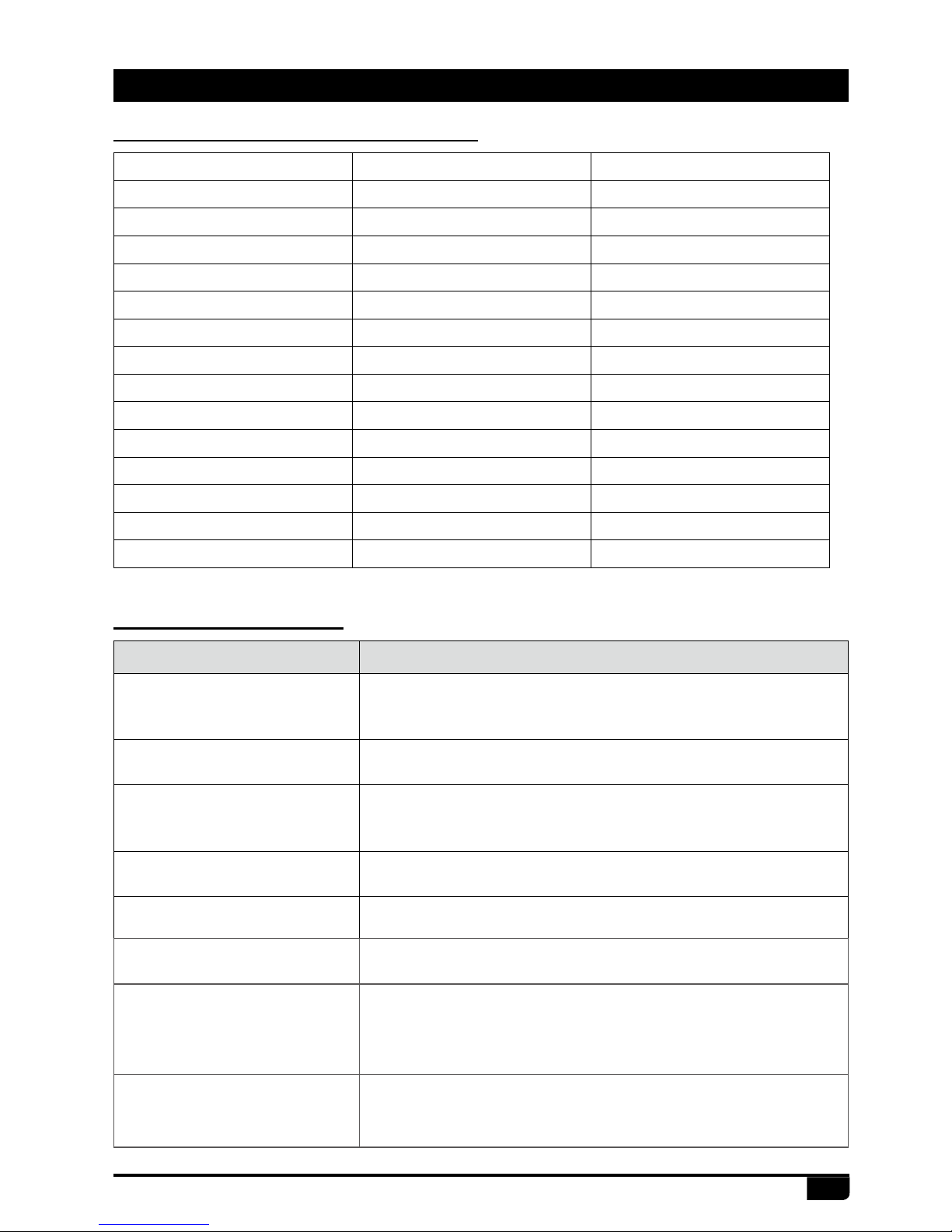
12.1 Default Setting after Resetting
12.2 Trouble Shooting
12. MAINTENANCE
Frequency band VHF UHF
VFO frequency 145.150MHz 431.150MHz
Memory channel -- --
Offset direction -- --
Offset frequency 600KHz 5MHz
Channel step 10KHz 10KHz
CTCSS encode and decode -- --
CTCSS tone frequency 88.5Hz 88.5Hz
DCS encode and decode -- --
DCS Code 000N 000N
Output power HI HI
TOT 3 3
APO OFF OFF
VOL 28 28
Squelch Level 3 3
Problem Possible Causes and Potential Solutions
(1) Power is on, nothing
appears on Display
+ and - polarities of power connection are reversed. Connect
red lead to plus terminal and black lead to minus terminal of
DC power supply
(2) Fuse is blown
Check and solve problem resulting in blown fuse and
replace fuse with new fuse
(4) No sound comes from
speaker
• Squelch is muted. Decrease squelch level.
• Tone or CTCSS/DCS squelch is active. Turn CTCSS or
DCS squelch off
(5) Key and Dial do not
function
Key-lock function is activated. Cancel Key-lock function
(6) No Scan Did not list the channel in the scan when programmed
The whole band with noise
after programmed
The squelch has opened during programmed
Communication range was
short, bad sensitivity
a. Check the antenna is well or not, and check the antenna
port whether well connected.
b. Antenna connector has debris or damaged. Whether set
Low power
Can not talk with other
members within the group
a. Frequency/channel different, pls modify
b. CTCSS/DCS different, pls reset
c. Out of the communication range
Page 32
29
RT95 UHF/VHF Two Way Radio
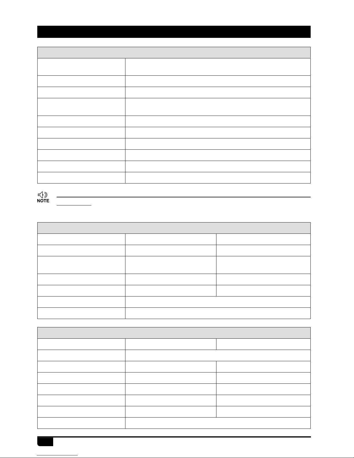
13. SPECIFICATIONS
GENERAL
Frequency Range
VHF: 144-146MHz UHF: 430~440MHz
Number of Channels 200 channels
Channel Spacing 25K (Wide Band) 20K(Middle Band) 12.5K (Narrow band)
Phase-locked Step
2.5KHz, 5KHz, 6.25KHz, 10KHz, 12.5KHz, 20KHz, 25KHz,
30KHz, 50KHz
Operating Voltage 13.8V DC ±15%
Squelch Carrier/CTCSS/DCS
Frequency Stability ±2.5 ppm
Operating Temperature -20℃~+60
℃
Dimensions(mm) 124 (W) x 163(D) x 39 (H)
Weight about 0.64Kg
TRANSMITTER
Wide band Narrow band
Sensitivity (12dB Sinad) ≤0.25μV ≤0.35μV
Adjacent Channel
Selectivity
≥60dB ≥60dB
Audio Response +1~-3dB(0.3~3KHz) +1~-3dB(0.3~2.55KHz)
Hum & Noise ≥45dB ≥40dB
Audio distortion ≤5%
Audio power output >2W@8
RECEIVER
Wide band Narrow band
Power Output 25W / 15W / 5W
Modulation 16KΦF3E 11KΦF3E
Adjacent Channel Powe
r
≥70dB ≥60dB
Hum & Noise ≥40dB ≥36dB
Spurious Emission ≥60dB ≥60dB
Audio Response +1~-3dB(0.3~3KHz) +1~- 3dB(0.3~2.55KHz)
Audio Distortion ≤5%
»
Specifications are subject to change without notice due to advancements in
technology.
Page 33
30
RT95 UHF/VHF Two Way Radio
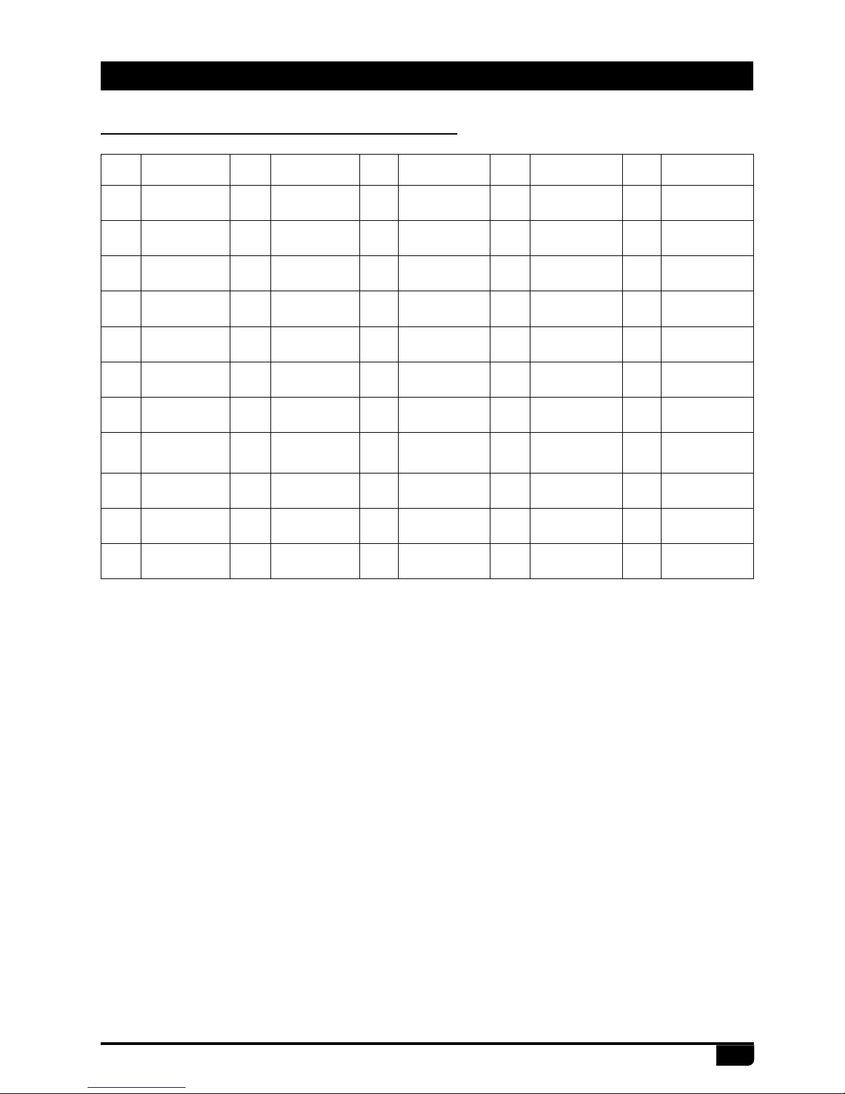
14. ATTACHED CHART
No. Freq.(Hz) No. Freq.(Hz) No. Freq. (Hz) No. Freq. (Hz) No. Freq. (Hz)
1 62.5 12 94.8 23 136.5 34 177.3 45 218.1
2 67.0 13 97.4 24 141.3 35 179.9 46 225.7
3 69.3 14 100.0 25 146.2 36 183.5 47 229.1
4 71.9 15 103.5 26 151.4 37 196.2 48 233.6
5 74.4 16 107.2 27 156.7 38 189.9 49 241.8
6 77.0 17 110.9 28 159.8 39 192.8 50 250.3
7 79.7 18 114.8 29 162.2 40 196.6 51 254.1
8 82.5 19 118.8 30 165.5 41 199.5 52
Self-
dene
9 85.4 20 123.0 31 167.9 42 203.5
10 88.5 21 127.3 32 171.3 43 206.5
11 91.5 22 131.8 33 173.8 44 210.7
52 groups CTCSS Tone Frequency(Hz)
Page 34
31
RT95 UHF/VHF Two Way Radio
Code
No.
DSC
(Octal)
Code
No.
DSC
(Octal)
Code
No.
DSC
(Octal)
Code
No.
DSC
(Octal)
Code
No.
DSC
(Octal)
Code
No.
DSC
(Octal)
Code
No.
DSC
(Octal)
Code
No.
DSC
(Octal)
1.
000
2.
001
3.
002
4.
003
5.
004
6.
005
7.
006
8.
007
9.
010
10.
011
11.
012
12.
013
13.
014
14.
015
15.
016
16.
017
17.
020
18.
021
19.
022
20.
023
21.
024
22.
025
23.
026
24.
027
25.
030
26.
031
27.
032
28.
033
29.
034
30.
035
31.
036
32.
037
33.
040
34.
041
35.
042
36.
043
37.
044
38.
045
39.
046
40.
047
41.
050
42.
051
43.
052
44.
053
45.
054
46.
055
47.
056
48.
057
49.
060
50.
061
51.
062
52.
063
53.
064
54.
065
55.
066
56.
067
57.
070
58.
071
59.
072
60.
073
61.
074
62.
075
63.
076
64.
077
65.
100
66.
101
67.
102
68.
103
69.
104
70.
105
71.
106
72.
107
73.
110
74.
111
75.
112
76.
113
77.
114
78.
115
79.
116
80.
117
81.
120
82.
121
83.
122
84.
123
85.
124
86.
125
87.
126
88.
127
89.
130
90.
131
91.
132
92.
133
93.
134
94.
135
95.
136
96.
137
97.
140
98.
141
99.
142
100.
143
101.
144
102.
145
103.
146
104.
147
105.
150
106.
151
107.
152
108.
153
109.
154
110.
155
111.
156
112.
157
113.
160
114.
161
115.
162
116.
163
117.
164
118.
165
119.
166
120.
167
121.
170
122.
171
123.
172
124.
173
125.
174
126.
175
127.
176
128.
177
129.
200
130.
201
131.
202
132.
203
133.
204
134.
205
135.
206
136.
207
137.
210
138.
211
139.
212
140.
213
141.
214
142.
215
143.
216
144.
217
145.
220
146.
221
147.
222
148.
223
149.
224
150.
225
151.
226
152.
227
153.
230
154.
231
155.
232
156.
233
157.
234
158.
235
159.
236
160.
237
161.
240
162.
241
163.
242
164.
243
165.
244
166.
245
167.
246
168.
247
169.
250
170.
251
171.
252
172.
253
173.
254
174.
255
175.
256
176.
257
177.
260
178.
261
179.
262
180.
263
181.
264
182.
265
183.
266
184.
267
185.
270
186.
271
187.
272
188.
273
189.
274
190.
275
191.
276
192.
277
193.
300
194.
301
195.
302
196.
303
197.
304
198.
305
199.
306
200.
307
201.
310
202.
311
203.
312
204.
313
205.
314
206.
315
207.
316
208.
317
209.
320
210.
321
211.
322
212.
323
213.
324
214.
325
215.
326
216.
327
217.
330
218.
331
219.
332
220.
333
221.
334
222.
335
223.
336
224.
337
225.
340
226.
341
227.
342
228.
343
229.
344
230.
345
231.
346
232.
347
233.
350
234.
351
235.
352
236.
353
237.
354
238.
355
239.
356
240.
357
241.
360
242.
361
243.
362
244.
363
245.
364
246.
365
247.
366
248.
367
249.
370
250.
371
251.
372
252.
373
253.
374
254.
375
255.
376
256.
377
257.
400
258.
401
259.
402
260.
403
261.
404
262.
405
263.
406
264.
407
265.
410
266.
411
267.
412
268.
413
269.
414
270.
415
271.
416
272.
417
273.
420
274.
421
275.
422
276.
423
277.
424
278.
425
279.
426
280.
427
281.
430
282.
431
283.
432
284.
433
285.
434
286.
435
287.
436
288.
437
289.
440
290.
441
291.
442
292.
443
293.
444
294.
445
295.
446
296.
447
297. 450
298.
451
299.
452
300.
453
301.
454
302.
455
303.
456
304.
457
305. 460
306.
461
307.
462
308.
463
309.
464
310.
465
311.
466
312.
467
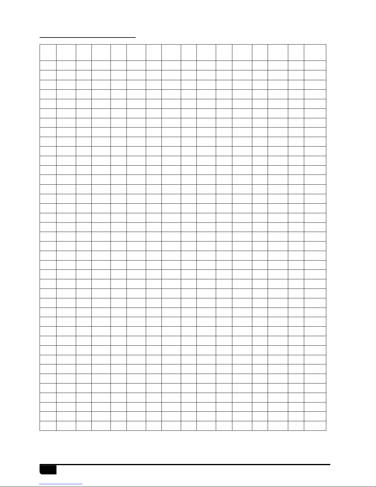
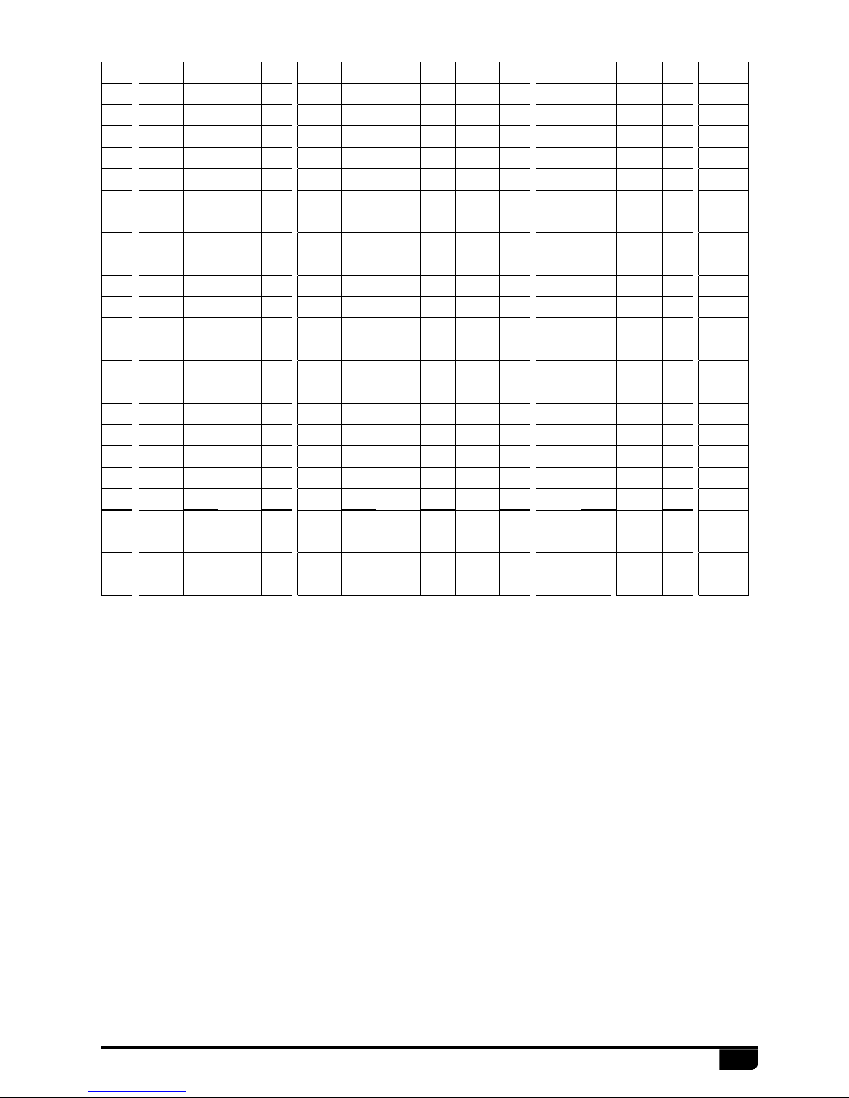
1024 groups DCS Code
Page 35
32
RT95 UHF/VHF Two Way Radio
313.
470
314.
471
315.
472
316.
473
317.
474
318.
475
319.
476
320.
477
321.
500
322.
501
323.
502
324.
503
325.
504
326.
505
327.
506
328.
507
329.
510
330.
511
331.
512
332.
513
333.
514
334.
515
335.
516
336.
517
337.
520
338.
521
339.
522
340.
523
341.
524
342.
525
343.
526
344.
527
345.
530
346.
531
347.
532
348.
533
349.
534
350.
535
351.
536
352.
537
353.
540
354.
541
355.
542
356.
543
357.
544
358.
545
359.
546
360.
547
361.
550
362.
551
363.
552
364.
553
365.
554
366.
555
367.
556
368.
557
369.
560
370.
561
371.
562
372.
563
373.
564
374.
565
375.
566
376.
567
377.
570
378.
571
379.
572
380.
573
381.
574
382.
575
383.
576
384.
577
385.
600
386.
601
387.
602
388.
603
389.
604
390.
605
391.
606
392.
607
393.
610
394.
611
395.
612
396.
613
397.
614
398.
615
399.
616
400.
617
401.
620
402.
621
403.
622
404.
623
405.
624
406.
625
407.
626
408.
627
409.
630
410.
631
411.
632
412.
633
413.
634
414.
635
415.
636
416.
637
417.
640
418.
641
419.
642
420.
643
421.
644
422.
645
423.
646
424.
647
425.
650
426.
651
427.
652
428.
653
429.
654
430.
655
431.
656
432.
657
433.
660
434.
661
435.
662
436.
663
437.
664
438.
665
439.
666
440.
667
441.
670
442.
671
443.
672
444.
673
445.
674
446.
675
447.
676
448.
677
449.
700
450.
701
451.
702
452.
703
453.
704
454.
705
455.
706
456.
707
457.
710
458.
711
459.
712
460.
713
461.
714
462.
715
463.
716
464.
717
465.
720
466.
721
467.
722
468.
723
469.
724
470.
725
471.
726
472.
727
473.
730
474.
731
475.
732
476.
733
477.
734
478.
735
479.
736
480.
737
481.
740
482.
741
483.
742
484.
743
485.
744
486.
745
487.
746
488.
747
489.
750
490.
751
491.
752
492.
753
493.
754
494.
755
495.
756
496.
757
497.
760
498.
761
499.
762
500.
763
501.
764
502.
765
503.
766
504.
767
505.
770
506.
771
507.
772
508.
773
509.
774
510.
775
511.
776
512.
777
http://radioaficion.com/hamfiles/
 Loading...