

Response Alarms SA3 Installation & Operating Manual
Installation & Operating Manual
SA3
6 Zone Wirefree
Alarm System
1
2
3
4
5
6
7
*
0
#
8
ESC
ENTER
ZONE 1 ZONE 2 ZONE 3 ZONE 4
ZONE 5 ZONE 6 FIRE TAMPER
9

FOREWORD
All components in this wirefree Alarm System are
designed and manufactured to provide a high standard
of security protection and long, reliable service.
The system is designed for ease of installation using
only conventional domestic tools. However, it is
essential that the installer reads and fully understands
the advice and procedures contained in this manual and
plans the system before proceeding with the installation.
During installation, it is important that the procedures
described in this manual are followed in sequence.
This manual should be retained in a safe place for
future reference.
IMPORTANT
All components, with the exception of the External
Solar Siren are suitable for mounting in dry interior
locations only.
DECLARATION
Novar ED&S hereby declares that this wirefree alarm
system is in compliance with the essential
requirements and other relevant provisions of the
Radio and Telecommunications Terminal Equipment
(R&TTE) directive, 1999/5/EC.
No radio operating licence is required for this equipment.
Tools and Equipment Required:
No.0 Philips Screwdriver Drill
No.1 Philips Screwdriver Bradawl
No.2 Philips Screwdriver Small Spirit Level
5 & 6mm Masonry Drill Bits
DEVICE RANGE
The quoted range of the system devices (see
component specification on rear cover) is measured
in ideal conditions. Any solid object (e.g. walls,
ceilings, reinforced PVC doors etc) placed between
the transmitter devices and the Receiver(s) will
reduce the transmission range of the devices.
The amount by which the range will be reduced is
dependant upon the nature of the barrier. e.g.
Wall Type Range Reduction
Dry-lined partition wall: 10-30%
Single layer brick wall: 20-40%
Double layer brick wall: 30-70%
Metal Panel/Radiator: 90-100%
Note: The effect on the range of multiple walls is
cumulative. i.e. if there are two brick walls in the way,
the range will be reduced by up to 40% by each wall.
SYSTEM SECURITY
This system has been designed to both detect
intruders and act as a strong deterrent to would-be
intruders when installed correctly.
Please remember that given adequate knowledge and
time it is possible to overcome any alarm system and
we therefore recommend that an Intruder Alarm is
used in conjunction with good physical protection
such as security window and door locks.
All units in the system are encoded to operate
together using an 8 bit House Code which is
configured by the user/installer to provide the unique
identification code for your installation. The system
House Code can be changed at any time by the user.
The system is operated from one or more Remote
Control units and/or the Control Panel. Care should
be taken to ensure that your Remote Control Unit(s)
are not lost or the User Access Codes for the Control
Panel do not become known to other people as this
will compromise the security of your system. In either
event the system house code and User Access Codes
should be changed as soon as possible.
SAFETY
Always follow the manufacturers advice when using
power tools; steps, ladders etc. and wear suitable
protective equipment (e.g. safety goggles) when
drilling holes etc.
Before drilling holes in walls, check for hidden
electricity cables and water pipes, the use of a
cable/pipe locater maybe advisable if in doubt.
When using ladders, ensure that they are positioned
on a firm stable surface at the correct angle and
suitably secured before use.
The use of ear defenders is advisable when working in
close proximity to the Siren due to the high sound
level produced by this device.
SA3 6 Zone Wirefree Alarm SystemFriedland
IMPORTANT: All units in your system must be set
to the same House Code which must be changed
from the factory supplied setting.

CONTENTS
Page No.
KIT CONTENTS 2
INTRODUCTION AND OVERVIEW
3
System Arming
3
Entry/Exit Delay
3
Zones
3
Zone Lockout
3
Tamper Protection
4
Jamming Detection
4
Battery Monitoring
4
System House Code
4
PLANNING AND EXTENDING YOUR WIREFREE
ALARM SYSTEM
5
REMOTE CONTROL UNIT
6
General Information
6
Configuring the Remote Control
7
CONTROL PANEL
7
Positioning the Control Panel
7
Installing the Control Panel
7
Configuring the Control Panel House Code
8
Testing the Control Panel & Remote Control
9
PASSIVE INFRA-RED (PIR)
MOVEMENT DETECTORS
10
Positioning the PIR Movement Detectors
10
Installing and Configuring the PIR
Movement Detectors
11
Testing the PIR Movement Detectors
12
MAGNETIC CONTACT DETECTORS
12
Positioning the Magnetic Contact Detectors
13
Installing and Configuring the Magnetic
Contact Detectors
13
Testing the Magnetic Contact Detectors
14
EXTERNAL SOLAR SIREN
14
General Information
14
Positioning the Solar Siren
15
Installing and Configuring the Solar Siren
15
Power-up of the Solar Siren
16
Testing the Solar Siren
17
Page No.
EXTERNAL CONNECTIONS
17
TESTING THE SYSTEM
17
Initial Testing
17
Testing An Installed System
17
FACTORY DEFAULTS
18
Reset Factory Default Conditions
19
PROGRAMMING
19
User Access Code
19
System House Code
19
Instant/Delay Zones
20
Entry/Exit Delay
20
Alarm Duration
20
Part-Arm
20
Zone Lockout
21
Entry/Exit Warning Tone
21
Jamming Detection
21
NO/NC Relay Contacts
22
Zone Operating Modes
22
OPERATING INSTRUCTIONS
23
Arming The System
23
Part-Arming The System
23
Disarming The System
23
Personal Attack (PA) Alarm
24
Tamper
24
Siren Service Mode
24
Siren Operating Mode
24
Battery Monitoring
25
MAINTENANCE
25
ALARM RECORD
26
TROUBLE SHOOTING
27
EXTENDING YOUR ALARM SYSTEM
29
COMPONENT SPECIFICATION
Back Cover
1SA3
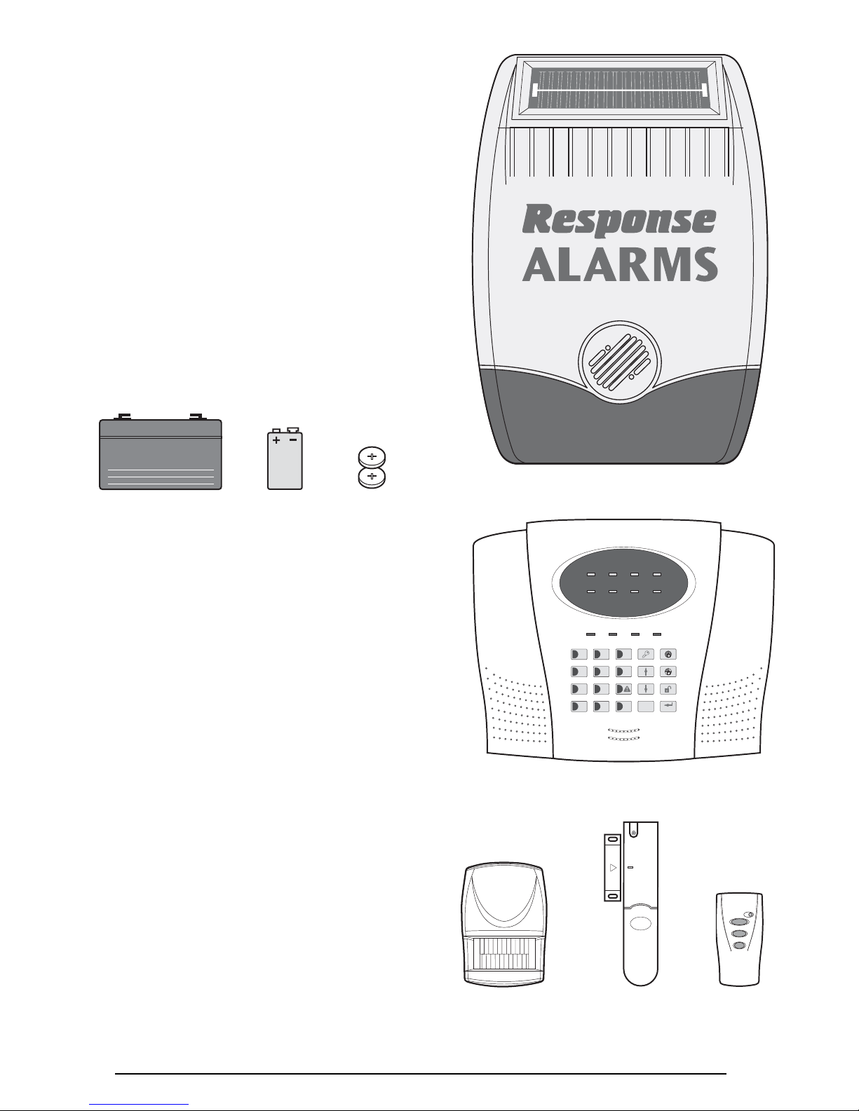
KIT CONTENTS
The Alarm System should contain the following
components.
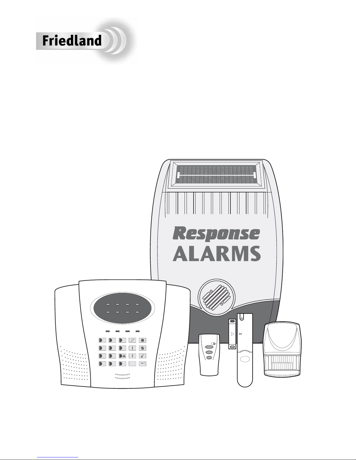
1xExternal Solar Siren
1xControl Panel
1xRemote Control
2xPIR Movement Detectors
2xMagnetic Contact Detectors
Also included:
Power Supply Adaptor
Installation & Operating Manual
Fixing pack
Batteries
EXTENDING THE ALARM SYSTEM
The following additional accessories are available to
enhance your system and provide further protection
and a higher level of security where required.
Component: Product Code
Two Magnetic Contact Detectors
and one Remote Control SU1
Tw o Passive Infra-Red
Movement Detectors SU2
Tw o Remote Controls SU3
Two Magnetic Contact Detectors SU4
Remote Keypad SU5
External Solar Siren SU6
Full details of these accessories are given on page 29.
2 SA3
1
2
3
4
5
6
7
*
0
#
8
ESC
ENTER
ZONE 1 ZONE 2 ZONE 3 ZONE 4
ZONE 5 ZONE 6 FIRE TAMPER
9
WP1.2-6
External Solar Siren
Control Panel
Magnetic
Contact
Detector
Remote
Control
PIR Movement
Detector
6V/1.2Ahr
Sealed lead acid battery
(supplied fitted in
Solar Siren)
9V PP3 Alkaline
battery
(for PIR Detectors)
3V CR2032
Lithium Cell
(for Remote
Control and
Magnetic Contact
Detectors)
INTRODUCTION AND OVERVIEW
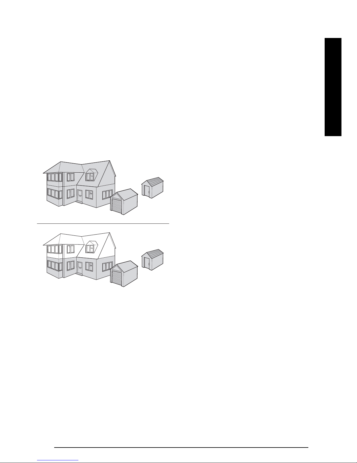
SYSTEM ARMING
The system has a full ‘Arm’ and a ‘Part-Arm’ mode.
Full ARM will arm all zones while the ‘Part-Arm’ will
only arm the zones that are enabled for “Part-Arm”.
For example:
The system could be configured such that during night
time, ‘Part-Arm’ would arm only zones protecting the
lower floor and outbuildings leaving the upper floor
free for movement without triggering the alarm.
However, when the property is left un-occupied, the full
‘Arm’ mode will arm all zones to protect the entire
property, (i.e. upper and lower floors and outbuildings).
ENTRY/EXIT DELAY
Each zone can be programmed to be Armed in either
Instant or Delay mode.
Usually the zone covering the main entrance door and
the route to and from the Control Panel would be
configured in Delay mode. This allows time for the
user to exit the property after setting the system at the
Control Panel or to Disarm the system before an alarm
condition is triggered when re-entering the property.
The remaining zones would be configured as Instant
allowing them to initiate an alarm immediately a
detector on the zone is triggered.
Delay Armed zones will not become fully armed until
after the Entry/Exit delay period has expired. When a
detector on a Delay Armed zone is triggered, an alarm
condition will not be triggered until after the Entry/Exit
period has elapsed. If the system is not disarmed
during the delay period, an alarm condition will occur
when the delay period expires.
Instant Armed zones are immediately able to initiate
an alarm as soon as the system begins to arm.
Note: To conserve power and maximise battery life
the PIR Detector will only detect movement if there
has been no movement detected within the previous
2 minutes. Consequently the PIR Detector will not
become active until the protected area has been free
from movement for more than 2 minutes.
ZONES
The system incorporates 6 wirefree Alarm Zones for
the connection of the system detectors that are used
to independently monitor different areas of the
property. In addition to standard intruder protection,
each zone may also be configured to operate in one of
three other modes:
- ‘Personal Attack’ mode provides 24 hour monitoring
of any Personal Attack (PA) switches incorporated
into the system.
- ‘24-hour Intruder’ mode provides 24 hour intruder
protection for areas where continuous monitoring is
required, (e.g. gun cupboards).
- ‘Fire’ mode provides 24 hour monitoring of any
Fire/Smoke detectors incorporated into the system.
ZONE LOCKOUT
If a detector on an active zone is triggered while the
system is armed an alarm condition will occur. After
the programmed alarm duration has expired the alarm
will stop and the system will automatically reset.
Subsequent detectors triggered will again initiate an
alarm condition. If a single zone initiates an alarm
condition more than three times then that zone will be
‘Locked Out’ and any further alarm signals from that
zone will be ignored until the system is disarmed.
Note: The ‘Zone Lockout’ feature can be disabled if
required.
SA3 3
Full Arm
Part-Arm
INTRODUCTION
TAMPER PROTECTION
All system devices (except any Remote Control
Units) incorporate Tamper protection features to
protect against unauthorised attempts to interfere
with the device.
Any attempt to remove the battery cover from any
device (except a Remote Control) or to remove the
Solar Siren or Control Panel from the wall will initiate
an alarm condition (unless the system is in Test or
Programming modes), even if the system is Disarmed.
JAMMING DETECTION
In order to detect any attempts to illegally jam the
radio channel used by your alarm system, a special
jamming detection function is incorporated into the
Control Panel and Solar Siren. If this feature is
enabled, and the radio channel is jammed
continuously for 30 seconds, when the system is
armed, the Solar Siren will emit a pre-alarm series of
rapid bleeps for 5 seconds. If the jamming continues
for a further 10 seconds or more a full alarm condition
will occur. In addition if the system is jammed for
more than three periods of 10 seconds in a 5 minute
interval, this will also generate a Full Alarm condition.
The Jamming Detection circuit is designed to
permanently scan for jamming signals. However, it is
possible that it may detect other local radio
interference operating legally or illegally on the same
frequency. If it is planned to operate the jamming
detection feature we recommend that the system is
monitored for false jamming alarms for at least 2
weeks prior to leaving the Jamming Detection function
permanently enabled.
Note: The jamming detection features incorporated
into the Control Panel and optional Solar Siren operate
independently.
BATTERY MONITORING
All devices powered by non-rechargeable batteries
incorporate a battery level monitoring feature which
will warn of a low battery status. In addition the
Control Panel will also indicate a low battery status
within any Passive Infra-Red or Magnetic Contact
Detector on the system. The batteries on any device
indicating a low battery status should be replaced
immediately.
SYSTEM HOUSE CODE
In order to prevent any unauthorised attempt to
operate or disarm your system, you must configure
your system to accept radio signals only from your
own system devices. This is done by setting a series
of eight miniature (DIP) switches in all devices
(except the Control Panel) to the same ON/OFF
combination (the House Code) selected by the
user/installer. The Control Panel is then programmed
to operate only with devices set to this House Code.
All detectors and Remote Control Unit(s) must be
configured with the same House Code in order for
the system to operate correctly.
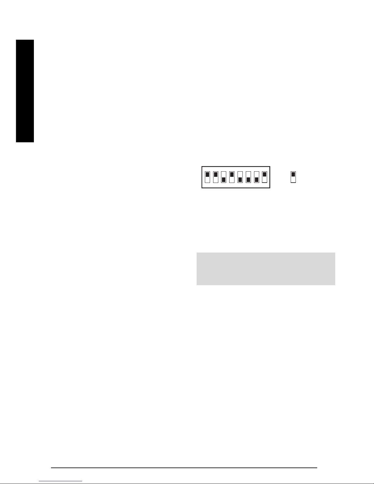
Inside the Siren, Detectors and Remote Control Unit is
a series of 8 DIP switches.
The House Code is set up by moving each of the 8
switches in each device to the same randomly selected
ON/OFF sequence. When setting the DIP switches,
ensure that each switch ‘clicks’ fully into position. Use
the tip of a ballpoint pen or a small screwdriver to move
each switch in turn.
SA34
e.g.
Switch 1
= set to ON
position
ON
1 2 3 4 5 6 7 8
INTRODUCTION
Note: It is recommended that the system House
Code is always changed to a code other than the
factory default.
Before attempting to install your Alarm System it is
important to study your security requirements and plan
your installation.
PIR Movement Detectors are used to protect the main
areas of the property, (e.g. lounge, study, hallway and
landing). Magnetic Contact Detectors are typically used
to protect the main access points to the property, (e.g.
front door, back door, patio doors). However, they can
also be used to protect other vulnerable doors/windows
or access doors to important rooms.
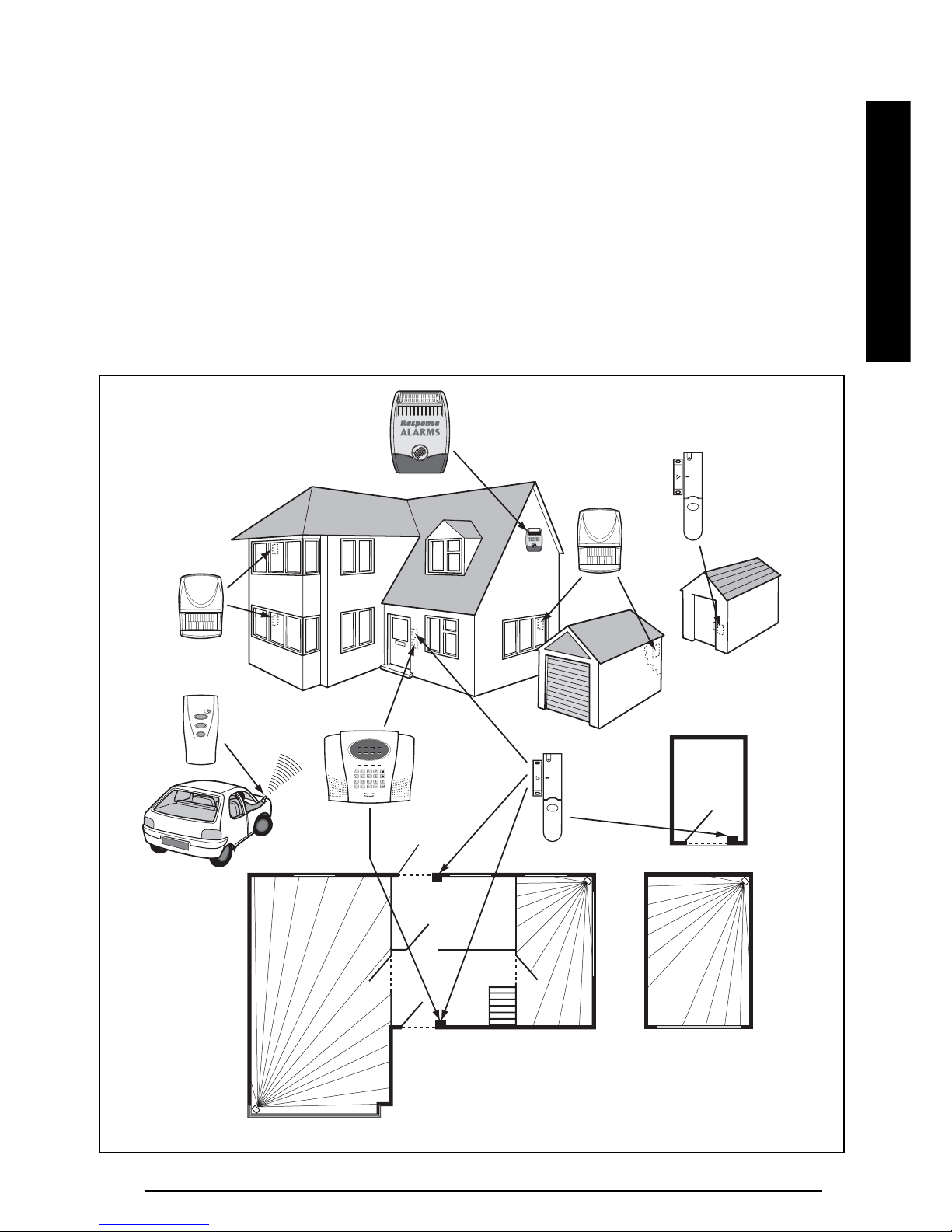
TYPICAL INSTALLATION
The following example below shows typical property
incorporating the suggested positions for the External
Siren, PIR and Magnetic Detectors. Use this as a
guide for your installation in conjunction with the
detailed positioning requirements for each device
provided in the appropriate installation sections in this
manual for planning your intruder alarm system.
PLANNING AND EXTENDING YOUR WIREFREE
ALARM SYSTEM
LED
Control
Panel
Magnetic
Contact
Detector
Magnetic Contact
Detector
External Solar
Siren
PIR Movement
Detector
PIR Movement
Detector
Remote
Control
SHED
LOUNGE
GROUND FLOOR
GARAGE
KITCHEN
HALL
DINNING
ROOM
PIR Movement
Detector
PIR
Movement
Detector
PIR
Movemen
t
Detector
Back Door
SA3 5
INTRODUCTION
SA36
Typical Installation using only detectors supplied:
1.
Place the 1st Magnetic Contact detector (set on
Zone 1) on the front door.
2.
Place the 1st PIR Detector (also set on Zone 1) in
the hall covering the Control Panel and routes
between downstairs rooms.
3.
Place the 2nd Magnetic Contact detector (set on
Zone 2) on the back or Patio doors.
4.
Place the 2nd PIR Detector either
i) downstairs in the main living room containing most
valuables, (set on Zone 3), or
ii) upstairs on the landing covering the access
routes between bedrooms and the stairs, (set on
Zone 5). This will be inactive if Part-Arm is used.
The system may be expanded with additional
detectors, Remote Controls and Keypads to provide
even greater protection. However the following rules
should be followed:
a) Any detectors covering the main door and the route
to the Control Panel should be set on zone 1 only.
b) Any detectors covering the remainder of the lower
floor should be set on zones 2 to 4 only.
c) Any detectors placed upstairs should be set on
zones 5 or 6 only.
The system default settings are pre-configured to
provide a basic functional system to suit most typical
basic installations:
• Zone 1 is configured as a Delay zone with a 30s
entry/exit delay.
As soon as installation is complete, this should be
changed to your own code that only you and other
system users know.
All other zones are instant.
• The system has a 3 minute alarm duration.
• Zone Lockout is enabled.
• PART-ARM is configured to operate with detectors
on zones 1 to 4 only. Detectors on zones 5 & 6 are
inactive in part-arm.
Note: If you wish to change the system configuration
away from the above example and system default
settings and customise it to your own unique
requirements then refer to the Programming section
on page 19.
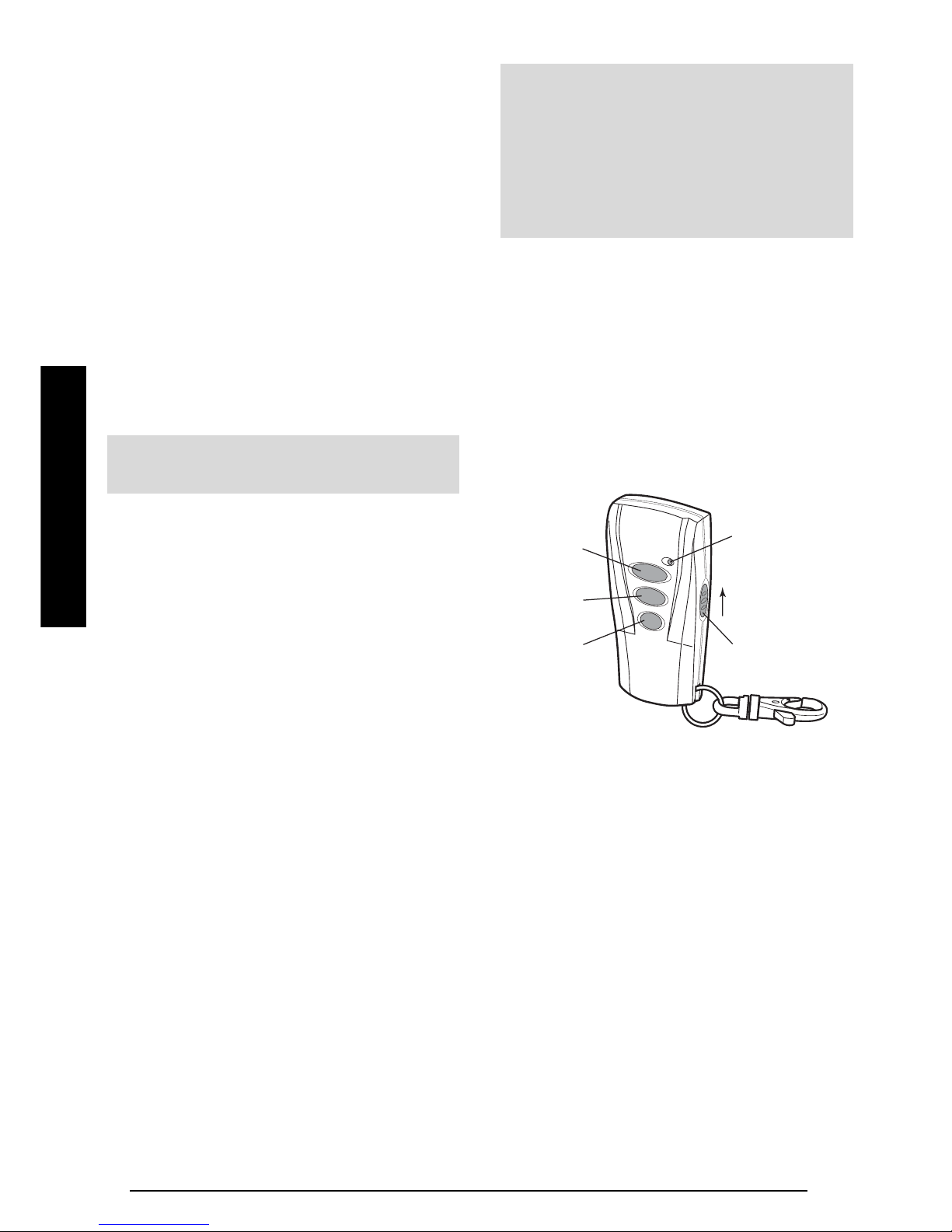
REMOTE CONTROL UNIT
The Remote Control Unit(s) are used to Arm, Part-Arm
and Disarm the system.
The Remote Control Unit also incorporates a Personal
Attack (PA) switch. Activating the PA switch on the
side of the Remote Control will immediately initiate a
Full Alarm condition whether the system is Armed or
Disarmed. The alarm can be cancelled by pressing
the ’DISARM’ button on the Remote Control or via the
Control Panel.
Any number of Remote Control Units can be used with
your system, providing they are all coded with the
system House Code.
The Remote Control is powered by a CR2032 type
Lithium cell which under normal conditions will have an
expected life in excess of 1 year. Under normal battery
conditions the LED on the Remote Control will only
illuminate when a button is pressed. However, under
low-battery conditions this LED will continue to flash
after the button has been released. When this occurs
the battery should be replaced as soon as possible.
Slide up
to operate
Transmit LED
Personal Attack
Arm
Part-Arm
Disarm
INSTALLATION
Note:
All system components must be set to the
same House Code.
IMPORTANT:
All system components must be set to the same
House Code.
The default User Access Code for the Control
Panel is "1234", this should be changed to your
own code that only you and other system users
know as soon as installation is complete.
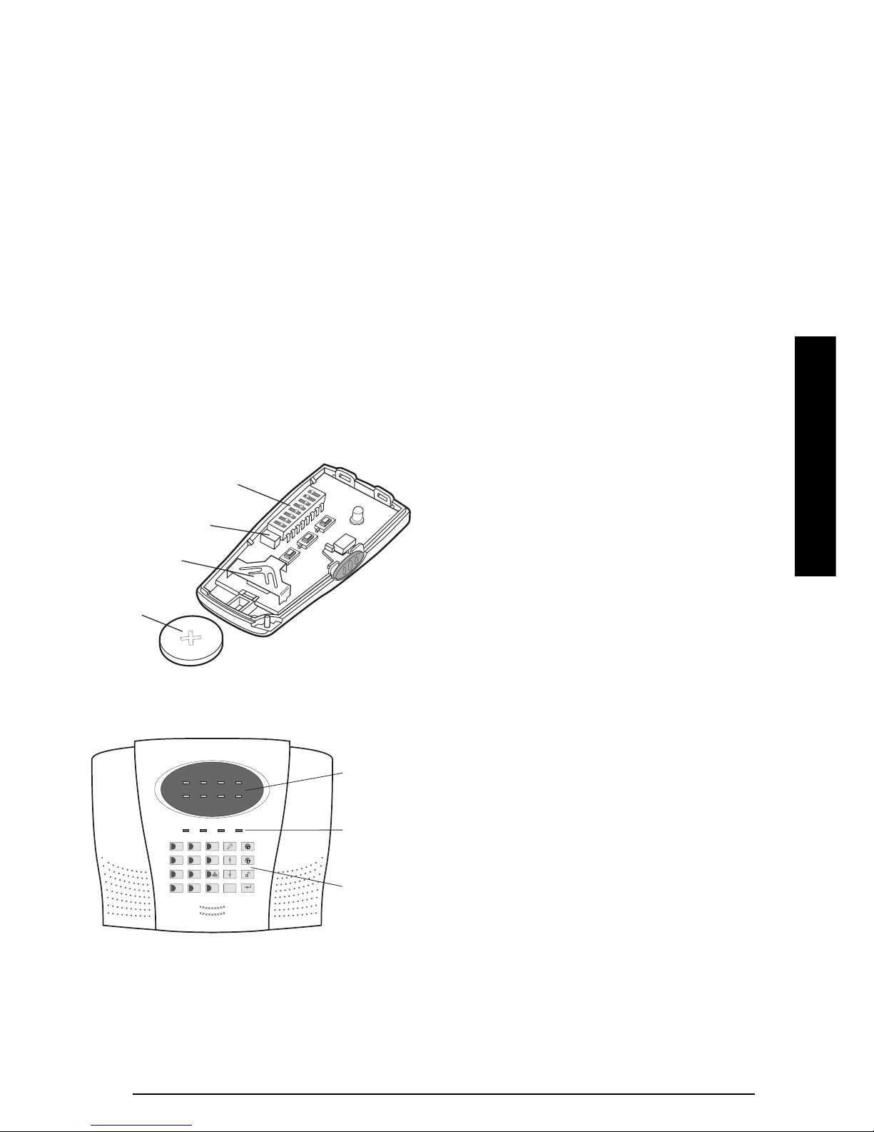
CONFIGURING THE REMOTE
CONTROL
1.
Remove the rear cover by undoing the small screw
on the rear of the Remote Control.
2. Select and record a random combination of ‘ON’ and
‘OFF’ positions for the DIP switches. This will be the
system House Code that enables all elements of your
transmitters to communicate with the Control Panel.
IMPORTANT: The House Code for your system
should be changed from the factory default setting.
3.
Ensure that the jumper link located immediately
below the House Code DIP switches is fitted in
position for use with this alarm system.
4.
Insert the battery under the clip ensuring that the
+ve terminal faces upwards away from the PCB.
5. Replace the rear cover and fixing screw. Do not over
tighten the screw as this could damage the thread.
CONTROL PANEL
Outside View of Control panel
POSITIONING THE CONTROL PANEL
When choosing a suitable location for the Control
Panel, the following points should be considered.
1.
The Control Panel should be located in a position out
of sight of potential intruders and in a safe location,
but easily accessible for system operation.
2.
The Control Panel should be mounted on a sound
flat surface to ensure that the rear tamper switch
on the Control Panel is closed when the Panel is
mounted. The Control Panel should be mounted
at a convenient height of between 1.5 and 2m and
in a position where it will be seen each day.
Note: If small children are in the household, a
further consideration should be given to keeping
the units out of their reach.
3. It is recommended that the Control Panel should
be positioned such that the Exit/Entry tone
(emitted by the Control Panel) can be heard from
outside the property.
4. The Control Panel should be mounted within a
protected area so that any intruder cannot reach
the Control Panel without opening a protected door
or passing through an area protected by a PIR
movement detector when the system is armed.
5. The Control Panel must be located within reach of
a mains socket.
6.
Do not locate the Control Unit closer than 1m to any
large metallic object, (e.g. mirrors, radiators, etc) as
this may affect the radio range of the Control Panel.
INSTALLING THE CONTROL PANEL
1.
Undo the two captive fixing screws on top of the
panel and open the cover. The cover is hinged
along the bottom edge.
2.
Unclip and remove the two back-up batteries on
either side of the panel.
3.
Hold the Control Panel in position on the wall and
mark the positions of the four fixing holes.
Remove the Panel and drill four 5mm holes and fit
the 25mm Wall Plugs.
Note: The wall plugs supplied with the product are
not suitable for plasterboard walls, if mounting the
Control Panel onto plasterboard use appropriate
wall plugs.
IMPORTANT: Do not drill the fixing holes with the
Control Panel in position; as the resulting dust and
vibration may damage the Control Panel’s internal
components and invalidate the guarantee.
House Code
DIP Switches
Jumper Link
Battery Clip
Battery
Zone LEDs
Status LED
s
Keypad
ENTER
ESC
123
4
5
6
789
0
*
#
ZONE 1 ZONE 2 ZONE 3 ZONE 4
ZONE 5 ZONE 6 FIRE TAMPER
SA3 7
INSTALLATION
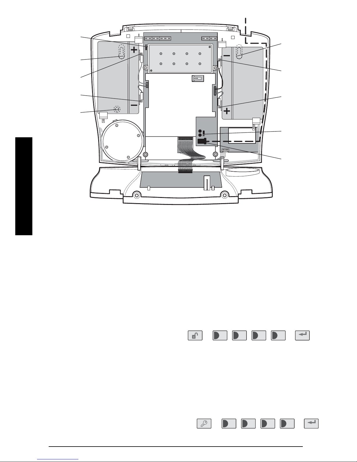
4.
Fit two 18mm No.4 screws into the top holes until
almost fully home and hang the Control panel
over these screws using the two keyhole slots in
the top corners of the panel casing.
5. Route the cable from the Power Supply Unit up
behind and on the right hand side of the Control
Panel and connect the plug to the DC power socket
in the panel, (see diagram above). Ensure that the
cable is not trapped between the panel and the wall.
6.
Fix the Panel to the wall using two 18mm No.4
screws in the lower two fixing holes in the panel and
tighten the upper fixing screws until they just grip
the casing. Do not over tighten the fixing screws as
this could damage or distort the casing.
7.
Ensure that the "Reset" and the "Hard-Wired
Siren tamper detect" jumper links are set in the
OFF position.
8.
Connect battery leads to both back-up batteries
and refit batteries.
Battery 1 (left): Red lead to +ve battery terminal
Blue lead to –ve battery terminal
Battery 2 (right): Blue lead to +ve battery terminal
Black lead to –ve battery terminal
IMPORTANT: Take care when connecting battery
leads to the batteries as connecting incorrectly
could damage the batteries or the Control Panel.
Note: The Power LED may flash to indicate that the
unit is being operated from the back-up batteries
and that mains supply is not present.
9.
Close the lid of the Control Panel and tighten the
captive fixing screws.
10.
Plug in and switch ON the Power Supply Unit, (the
Power LED should illuminate).
Note: If the Panel Tamper alarm sounds during the
installation reset the alarm by pressing:
, ,
on the Control Panel.
CONFIGURING THE CONTROL
PANEL HOUSE CODE
With unit in Standby mode (Power LED only
illuminated).
1. Press
, ,
1
2
3 4
ENTER
8 SA3
TAMP GND B+ GND N.C. C N.O. GND V+ OUT GND
Upper Keyhol
e
Fixing Hole
-
ve Terminal
(Black Lead)
+ve Terminal
(Blue Lead)
Reset Jumper
Link P1
Power Supply
Jack Socket
Upper Keyhole
Fixing Hole
+ve Terminal
(Red Lead)
-
ve Terminal
(Blue Lead)
Lower Fixing
Hole
External Tamper
Switch Jumper
Link P51
Power Supply
Cable Route
Inside View of Control Panel
1
2
3 4
ENTER
User Access Code
User Access Code
INSTALLATION
 Loading...