

Response Alarms PA6, PA8 Installation & Operation Manual
Installation & Operating Manual
PA6/PA8
6 Zone Wired Intruder
Alarm System
Zones
1 2 3 4 5 6
Attack
Tam per
Day
01234
Power
56789
CHIME OMIT
RESET
SETPROG

FOREWORD
The PA6 and PA8 Alarm Systems are designed for ease of
installation using only conventional domestic tools. However,
it is essential that the installer reads and fully understands the
advice and procedures contained in this manual and plans
the system before proceeding with the installation.
All components are designed and manufactured to provide a
high standard of security protection and long, reliable service.
During installation, it is important that the procedures
described in this manual are followed in sequence.
This manual should be retained in a safe place for future
reference.
Note:
The PA6 system is not supplied with the Remote
Keypad. All references to planning, installation and operation
of the Remote Keypad should be ignored for the PA6 system
and are only applicable to the PA8 system.
only.
Tools and Equipment Required:
3mm flat bladed screwdriver Bradawl
No.1 Philips Screwdriver Drill
No.2 Philips Screwdriver 5 & 6mm Masonry Drill Bits
Wire Cutters & Strippers Hammer
Additional Requirements:
Te rminal Strip or Insulating Tape
Back-up Battery: BUB12/1.2
12V/1.2Ah Sealed Lead-Acid type
SAFETY WARNINGS
Before proceeding with the installation, please note the
following safety warnings:
1. For safety reasons, the complete system operates at
13V powered from the Control Panel transformer, which is
connected to the mains supply. The Control Panel has
facilities for a 12V, 1.2Ahr Rechargeable Back-up Battery to
power the system in the event of a mains failure. It is
strongly recommended that a Back-up Battery is purchased
and installed in the Control Panel and that the complete
installation and testing of the system is undertaken with the
Control Panel powered from the Back-up Battery only.
Note: Where a Control Panel Back-up Battery is not
readily available it is recommended that the Control
Panel's connected to a 13 Amp, 3 pin plug (fused 3A)
via a 5A, 3 core mains cable until the installation is
complete. This will enable the Control Panel to be
readily switched ON and OFF where indicated during
installation in lieu of connecting/disconnecting the
Back-up Battery.
DANGER - 240 VOLTS. To prevent the risk of electrocution,
it is essential to turn off the mains electricity supply to the
Control Panel before commencing installation and work
within the Control Panel.
Do not permanently connect the mains supply until the
installation is complete.
The permanent mains supply to the control panel must
come from an un-switched fused connection unit (fitted
with a 3A fuse) directly connected to the mains
consumer unit. It should not be connected to circuits
supplying domestic appliances, (e.g. washing machines,
etc), as these types of appliances may cause the system
to malfunction.
The mains supply to this product should be installed by a
competent person (e.g. a qualified electrician) in accordance
with the instructions contained with the product and in
accordance with the appropriate clauses of the current
edition of the IEE wiring regulations (BS7671).
2. It is essential that all connections are made as
instructed, that cables are not stressed and that
terminals are fully tightened.
3. Always follow the manufacturers advice when using
power tools; steps, ladders etc. and wear suitable
protective equipment (e.g. safety goggles) when drilling
holes and hammering home cable clips etc.
4. Before drilling holes in walls, check for hidden electricity
cables and water pipes. The use of a cable/pipe locater
maybe advisable if in doubt.
SYSTEM SECURITY
This system has been designed to both detect intruders and
act as a strong deterrent to would-be intruders.
Please remember that given adequate knowledge and time
it is possible to overcome any alarm system and we
therefore recommend that an Intruder Alarm is used in
conjunction with good physical protection such as security
window and door locks.
PA6/PA8 - 6 Zone Wired Intruder Alarm SystemFriedland
IMPORTANT
All components, with the exception of the External
Siren & Strobe, are suitable for mounting in dry interior
locations only.
Internal mounted components must not be exposed
to dripping or splashing water and liquid filled objects
must not be placed on it.

1
CONTENTS
Page No.
KIT CONTENTS 2
INTRODUCTION & OVERVIEW 3
Control Panel 3
Remote Keypad 3
Passive Infra-Red Movement Detectors 3
Magnetic Contact Sets 3
External Siren & Strobe 4
SYSTEM FEATURES 4
Arm/Disarm 4
Quick Set 4
Event Replay 4
Chime 4
Reset 4
Programming 4
Detection Zones 4
Personal Attack (PA) Zone 4
24 Hour Tamper Circuit 4
Siren & Strobe Anti Tamper Monitoring 4
Keypad Security 4
Programmable Zone Options 5
Zone Entry Modes 5
Program Exit Modes 5
General System Programmable Options 5
PLANNING THE INSTALLATION 6
Control Panel And Remote Keypad 6
Mains Wiring 6
Detector Wiring 6
Magnetic Contact Sets 6
PIR Movement Detectors 6
External Siren & Strobe 7
Installation Example 7
INSTALLING THE CONTROL PANEL AND
REMOTE KEYPAD 8
Mounting The Control Panel 8
Mounting The Remote Keypad 9
Wiring The Remote Keypad 9
Testing The Control Panel (and Remote Keypad) 10
INSTALLING THE PIR MOVEMENT DETECTORS 10
Mounting The PIR Movement Detectors 11
Wiring The PIR Movement Detectors 11
Testing The PIR Movement Detectors
At The Control Panel 14
TYPICAL WIRING ARRANGEMENTS 12-13
Page No.
INSTALLING THE MAGNETIC CONTACTS 14
Wiring The Magnetic Contacts 15
Testing Magnetic Contacts At The Control Panel 16
INSTALLING THE EXTERNAL SIREN & STROBE 16
Mounting the External Siren & Strobe Enclosure 16
Wiring the Siren & Strobe Unit 16
CONNECTING THE CONTROL PANEL
MAINS SUPPLY 17
PROGRAMMING 18
To Enter Programming Mode 18
Exit Timer 18
Entry Timer 18
Alarm Duration 18
Main User Access Code 18
Second User Access Code 18
Installer Access Code 19
Omit Prevent Zones 19
Program And Zone Set Up 19
To Exit From Programming Mode 19
Reset To Factory Set Default Conditions 20
TESTING THE SYSTEM 20
OPERATING INSTRUCTIONS 20
To Arm The System 20
To Set A Program 20
Faults During Setting 21
To Omit A Zone 21
Quick Set 21
To Disarm The System 21
Chime 21
Auto Reset and Re-Arm 21
Day LED 21
Power LED 21
Alarm Memory Recall 21
MAINTENANCE 22
Control Panel, Keypad & Detectors 22
Rechargeable Batteries 22
Control Panel Fuses 22
ALARM RECORD 22
TROUBLE SHOOTING 23
EXTENDING YOUR ALARM SYSTEM 24
COMPONENT SPECIFICATION Back Cover
PA6/PA8 Alarm
INTRODUCTION
2 PA6/PA8 Alarm
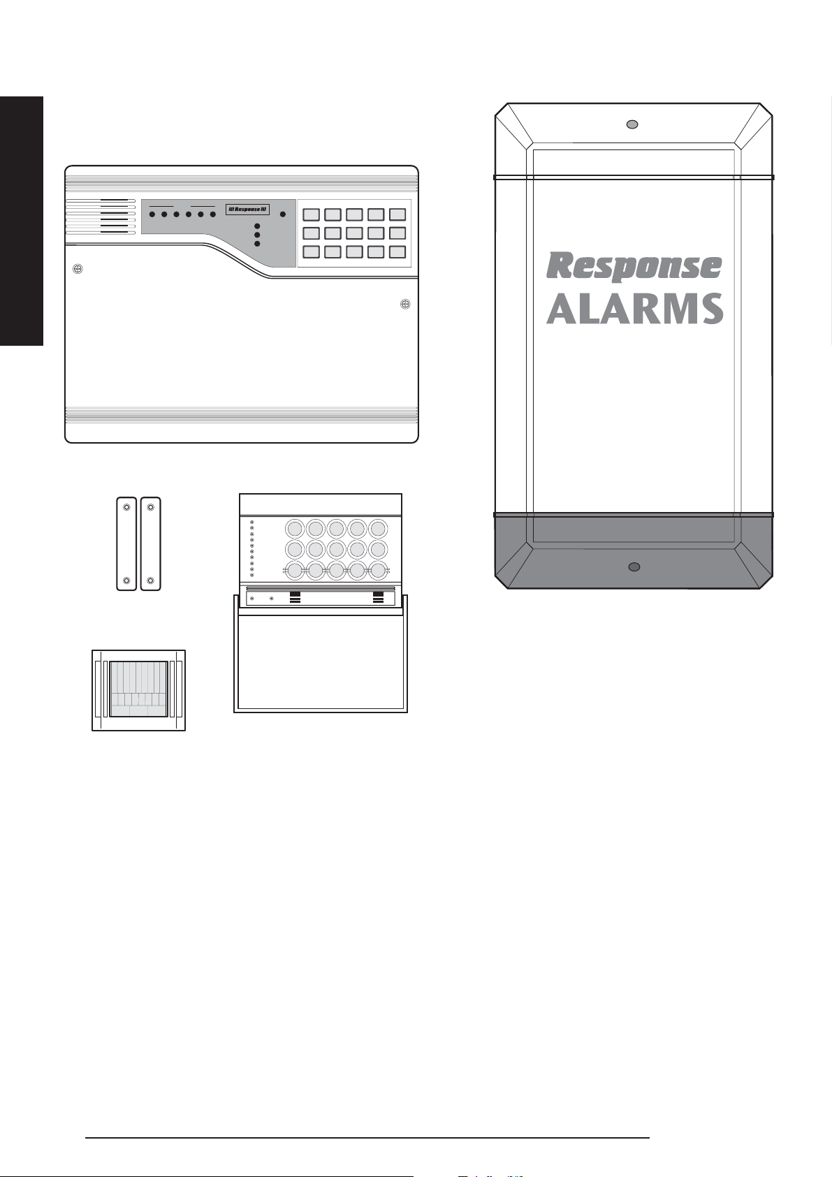
KIT CONTENTS
The PA6 and PA8 Alarm kits contain the following
components.
1 x 6 Zone Control Panel
1 x Remote Keypad
(PA8 only)
1 x External Siren & Strobe
2 x Passive Infra-Red Detectors
(PA8 contains 4 PIRs)
2 x Magnetic Contact Sets
2 x 50m coils of 6 Core Cable
1 x Fixings Pack
Also included:Installation & Operating Manual
Siren Cover Sticker
Window Warning Stickers
IMPORTANT
Please check all items are present BEFORE breaking the
packaging warranty seals. No claims for missing parts will
be accepted unless pack seals are in place and intact.
EXTENDING THE ALARM SYSTEM
The following additional accessories are available to enhance
your system and provide further protection and a higher level
of security where required.
Component Product Code
Accessory Pack containing:
2 x Passive Infra-Red Movement Detectors
2 x Magnetic Contact Sets
25m coil of 6 Core Cable PU1
Passive Infra-Red Movement detectors (Twin Pack) PU2
Full details of these accessories are given on page 24.
External Siren & Strobe
Control Panel
2 x Sets of Magnetic
Contacts
2 x PIR Movement
Detectors
(PA6)
(PA8 contains 4 PIRs)
Remote Keypad
Zones
1 2 3 4 5 6
Attack
Tam pe r
Day
01234
Power
56789
CHIME OMIT
Zone 1
Zone 2
0 1234
Zone 3
Zone 4
Zone 5
Zone 6
56789
Zone 7
Zone 8
Tamper
Chime Omit Reset Prog Set
Attack
Day Power
RESET
SETPROG

INTRODUCTION
3PA6/PA8 Alarm
The PA6 and PA8 Alarm kits contain all components
necessary to install a complete system. The items included
in your package are shown opposite, the main components
are as follows:-
CONTROL PANEL
The Control Panel is the heart of the intruder alarm system
and contains the microprocessor and electronic circuitry
necessary to monitor the various detection circuits (Zones)
and to initiate an alarm condition in the event of an intrusion
into a protected area.
The complete system operates at 13 Volts powered from
the Control Panel transformer which is connected to the
mains supply.
The Control Panel is operated via the push buttons on the
front of the Control Panel allowing the user to Arm/Disarm
the system, view the event record and test the system. A
four digit Main User Access Code and Optional Second User
Access Code ensures that only authorised users can
operate the system.
A separate Installer Access Code allows access to the
programming functions at the Control Panel. The Control
Panel also contains a small speaker used to indicate various
conditions by means of a variety of tones.
The Control Panel incorporates a ‘Non Volatile Memory’,
(NVM) which records all program and system settings
indefinitely even when all power has been removed.
The Control Panel will also remember which mode it was in
when power was disconnected and revert to this mode
when power is restored, e.g. if the panel was in Alarm Mode
when the power was removed, the panel will continue to be
in Alarm Mode when power is restored.
REMOTE KEYPAD (PA8 only)
The Remote Keypad has the facilities to duplicate all the
operation and control functions of the main Control Panel;
thus allowing the Control Panel to be located out of general
sight or to suit cable routing.
PASSIVE INFRA-RED MOVEMENT
DETECTORS
PIR detectors are designed to detect movement in a
protected area by detecting changes in infra-red radiation
levels caused for example when a person moves within or
across the devices field of vision. If movement is detected,
an alarm condition is generated at the Control Panel (if the
system is armed). PIR detectors will also detect animals, so
ensure that pets are not permitted access to areas fitted
with Passive Infra-Red Movement Detectors when the
system is armed.
Additional Passive Infra-Red Movement Detectors can be
purchased separately, if required.
MAGNETIC CONTACT SETS
The Magnetic Contact Set comprises two parts; a Magnetic
Contact Switch and a Magnet. They are designed to be
fitted to either doors or windows with the Magnet fixed to
the moving/opening part and the Contact Switch fixed to the
fixed door or window frame. When the protected door or
window is closed the Contact Switch is held closed by the
Magnetic field from the Magnet. Opening the protected
door or window will remove the magnetic field and allow the
Contact Switch to open generating an alarm signal at the
Control Panel, (if the system is armed).
Additional accessory packs including Magnetic Contact
Sets can be purchased separately, if required.
INTRODUCTION & OVERVIEW
SYSTEM OPERATION AFTER
POWER FAILURE
If a power failure occurs while the system is armed and
backup batteries are not fitted (or flat) then when
power is restored the system will be in its previously
armed state. If there are any PIR detectors wired to
any active zone then an alarm will initially occur. The
siren will sound for the set alarm duration after the 3-4
minutes required for the PIR detectors to stabilise.
This is because the PIR detectors require a period of
3-4 minutes to stabilise before they operate correctly
and during this period they effectively generate an
alarm signal to the Control Panel.
Note: Although optional, it is strongly recommended
that backup batteries are fitted.
All detectors and alarm circuits are wired from the
Control Panel and operate at 12 Volts dc.

INTRODUCTION
PA6/PA8 Alarm4
EXTERNAL SIREN & STROBE
The External Siren enclosure houses the 110dB Siren &
Strobe Unit, which when assembled, installed and wired to
the Control Panel will activate in the event of an intrusion
with the system armed. In the event of the cable to the
Siren & Strobe Unit being deliberately cut or the supply to
the Control Panel being interrupted, the External Siren will
operate from its own internal battery. For this reason, it is
recommended that a 12V 1.2Ah Back-up Battery is fitted to
the main Control Panel.
The Siren enclosure also features an anti-tamper device,
which will cause an alarm to activate if either the front
cover is removed or the complete assembly is pulled off
the wall.
To comply with local Noise Abatement Legislation, timers
are incorporated both in the Control Panel and Siren &
Strobe Unit to silence the siren after a pre-determined
time. The Control Panel timer is factory pre-set to 20
minutes, but can be set by the user between 01 minute and
99 minutes. The Siren & Strobe Unit timer limit is factory
pre-set to 20 minutes, but can be reduced to 3 minutes by
cutting an on-board link. The Siren will reset with the
Control Panel timer but will not continue beyond the set
Siren timer limit (i.e. 20 or 3 minutes).
A strobe warning light is incorporated into the external
siren enclosure and will flash in the event of an alarm to
provide a visual indication.
Note: The strobe light will continue to flash after the siren
has stopped to indicate that an alarm has occurred.
SYSTEM FEATURES
ARM/DISARM
The system has an easy arming facility. To fully arm the
system simply enter a valid User Access Code. The system
also has facilities to pre-program 3 Set routines or
‘Programs’.
The button enables you to omit a Zone(s) from a
program on a once only or temporary basis.
QUICK SET
The final arming of the system can be quicker. This is
useful for night setting when the Entry/Exit sounder can
be silenced after just a few seconds.
EVENT REPLAY
The Control Panel incorporates a memory capable of
storing 8 alarm events. Event replay will enable the user to
establish which Zones have been activated if an alarm has
occurred.
CHIME
Chime is a low security application for use when the system
is Standby. When a Zone that is set to chime is operated,
the internal sounder will produce a low volume two stage
warning tone and the Zone LED will illuminate.
A typical use of the Chime function would be in a shop to
warn of a customer’s presence or in a house to warn that a
door or particular area has been accessed.
RESET
Pressing this button clears any previously entered
information at the keypad, e.g. incorrect buttons pressed
and also clears any Fault Lights, unless the fault still exists.
PROGRAMMING
When a valid installer code has been entered, access to
programming the various system options will be permitted.
DETECTION ZONES
The Control Panel incorporates 6 detection Zones for the
connection of the system detectors. The function of each
Zone is fully programmable in each of 3 setting programs.
24 HOUR TAMPER CIRCUIT
Many system components incorporate tamper protection
facilities and the associated wiring can be monitored on
a 24 hour basis to generate an alarm condition if the
equipment or wiring is interfered with. It is recommended
that all system components with tamper facilities are
monitored for tamper.
SIREN & STROBE ANTI TAMPER MONITORING
Wiring to the external Siren housing is monitored on a
24 hour basis. In the event of the wiring to the external
housing being damaged or deliberately cut, or the housing
opened or completely removed, the Control Panel will
initiate an alarm condition and the External Siren will sound,
powered from the siren’s integral Back-up Battery.
KEYPAD SECURITY
The Control Panel and Remote Keypad are protected from
unauthorised disarming by means of initiating a Tamper
Alarm if more than 20 incorrect key pushes are made.
OMIT

INTRODUCTION
PROGRAMMABLE ZONE OPTIONS
The Control Panel uses 3 Set routines known as Programs.
In each Program the Exit Mode can be changed and the
Zone may be set up to have a different function.
The examples below show how 3 typical Programs could be
used in a house.
Program 1: To arm all of the Zones and become Set as the
user leaves the property and closes the final door.
Program 2: To protect the perimeter of the property in the
evening and become Set after say 20 seconds.
Program 3: To protect the downstairs areas of the house at
night and become Set instantly and silently.
ZONE ENTRY MODES
TIMED:
This function would be used to protect the main Entry/Exit
door or the first sensor in the entry route.
Opening the door or operating the sensor whilst the system is
Set will start the Entry timer and allow time to Unset the system.
WALK THROUGH:
This is used for detectors located between the main
entry/exit door or sensor and the Control Panel or Keypad.
On entry, once a Timed Zone has been operated and the
Entry Timer started, the Zone will be inhibited and allow
access through to the Control Panel or Keypad.
But when the system is Set, the Zone is fully active and will
cause an instant alarm activation.
INSTANT:
This function would be used for all Zones that are not part
of an entry route and will immediately cause a full alarm
condition when activated.
PROGRAM EXIT MODES
TIMED:
A Timed Program will become Set as the Exit timer expires.
FINAL DOOR:
A Final Door Program will be Set 5 seconds after a timed
Zone has opened and closed.
If a timed Zone is not operated during the Exit period, the
system will NOT Set.
INSTANT:
An Instant Program will be Set silently 3 seconds after the
Exit route has been initiated.
Note: If a Program is not selected when the user Sets
the system, Program 1 will automatically Set. Therefore
Program 1 is usually considered as the ‘Full Set Program’
containing all of the Zones.
GENERAL SYSTEM PROGRAMMABLE OPTIONS
ENTRY TIME:
Factory Default setting: 30 seconds
This is the time programmed to allow the user to reach the
Control Panel or Remote Keypad to disarm the system before
a full alarm occurs. The Entry time may be set between 10 990 seconds in 10 second intervals, depending on your
requirements. If the system is not disarmed during the Entry
delay period, a full alarm will occur when the Entry time expires.
EXIT TIME:
Factory Default setting: 30 seconds
This is the time programmed to allow the user to exit the
premises before the system fully arms. The Exit time may be
set between 10 - 990 seconds in 10 second intervals,
depending on your requirements. You will need to leave all
protected areas and close protected doors/windows before
the Exit time expires or a full alarm will occur.
Note: If a Zone is open when the system is arming the
Control Panel will emit a tone (different to the Entry/Exit tone)
to indicate a Zone is open. It is not possible to Arm the
system until the Zone is clear or omitted before arming.
ALARM DURATION::
Factory Default setting: 20 minutes
This is the time that the alarm will sound for following an
alarm activation. The Alarm Duration can be set to between
01 - 99 minutes, depending on individual requirements.
Note: The maximum length of time that the External Siren
will sound for when activated is set within the Siren & Strobe
to either 3 or 20 minutes.
SYSTEM RESET:
System Reset (return all options to factory settings). If the
User/Installer Access Codes have been lost or forgotten, or
the installer is unsure of the programmed options, it is
possible to return the Control Panel program to the factory
default settings. All previously programmed options will be
cleared and the system will require re-programming.
USER ACCESS CODE:
Factory Default setting: Main User - 0123
Second User - not programmed
Two User Access Codes are available to Arm/Disarm and
test the system. Each code is 4 digit, selectable from
5PA6/PA8 Alarm

INSTALLATION
0000 - 9999. However, the Main User Access Code has
the authority to add, change or delete the Second User
Access Code. The User Access Codes should be changed
from the factory default settings during programming after
installation is complete.
INSTALLER ACCESS CODE:
Factory Default setting: 9999
To allow programming of the system options, a unique
Installer Access Code must be entered at the Control Panel
Keypad. The Installer Access Code should be changed from
the factory default setting during programming after
installation is complete.
Note: For security reasons, once the system has been
Armed by the User Access code, the Installer Access code
cannot be used to reprogram the system.
Note: The User Access Codes and the Installer Access
Code should all be different.
PLANNING THE
INSTALLATION
GENERAL
Before attempting to install any wiring or system
components, it is recommended that a plan of the proposed
installation is prepared. This should help the installation to
be completed using the most unobtrusive and effective
methods. The following guidelines should be followed and
used in conjunction with the example provided when
preparing your own system plan.
CONTROL PANEL AND REMOTE KEYPAD
(Remote Keypad PA8 only)
The Control Panel & Remote Keypad should be located in a
position out of sight of potential intruders and in a safe location,
but accessible for system operation. Typically, the Control Panel
may be located in a small cupboard under the stairs (or other)
close to the mains supply and for ease of cable installation, with
the Keypad located adjacent to the main Entry/Exit door. An
ideal mounting height would be the same as a household light
switch or similar. If small children are in the household, a further
consideration should be given to keeping the units out of reach.
However, the final positions of the Control Panel and Keypad will
depend on the individual user’s requirements.
Note: Also consider the user’s ability to hear the Exit/Entry
tone (emitted by the Control Panel) effectively when setting
the system. It is preferable that the Exit tone can be heard
from outside the property when arming the system.
MAINS WIRING
Mains wiring to the Control Panel should come from an
independently supplied, un-switched fused connection unit
(fitted with a 3A fuse) located close to the Control Panel.
It is not advisable to connect the supply to other household
circuits, as this may cause the system to malfunction. Attempt
to keep the mains cable run as short as possible between the
fused connection unit and the Control Panel, (less than 3m).
IMPORTANT: The mains supply to this product should be
installed by a competent person (e.g. a qualified electrician)
in accordance with the instructions contained with the
product and in accordance with the appropriate clauses of
the current edition of the IEE wiring regulations (BS7671).
It would be an advantage to have the mains supply connection
unit fitted prior to commencing the installation to avoid any
unnecessary delay in fully commissioning your system.
Note: The mains wiring should be kept separate from wiring
to the detectors, both within the premises and on entering
the Control Panel. Always route mains and detector wiring
separately, preferably 300mm apart.
DETECTOR WIRING
Where only one detector per Zone is to be connected, the
cable should be run directly to the detector. However, if
more than one detector is to be connected to a Zone, either
(a) run all cables back to the Control Panel or (b) run one
cable to the Control Panel and link the detector contacts in
‘Series’ and power supplies in ‘Parallel’. (Refer to example
installation wiring diagrams on pages 12-13.
MAGNETIC CONTACTS
The Magnetic Contact is suitable for mounting in dry interior
locations only.
Decide which doors and windows are to be protected by fitting
Magnetic Contact switches. Usually the front and back doors
will have Magnetic Contact Switches fitted. Additional contacts
may be fitted where required to other more vulnerable doors or
windows, e.g. garage, patio and conservatory doors etc.
Note: It is not recommended to connect more than ten Magnetic
Contacts to any one Zone, as this may cause difficulty in wiring
and hinder any attempt to remedy wiring faults efficiently.
PIR MOVEMENT DETECTORS
When considering and deciding upon the mounting position
for the detector the following points should be considered to
ensure trouble free operation:
PA6/PA8 Alarm6

INSTALLATION
1. Ideally the detector should be positioned in a corner of the
room to be protected where the logical path of an intruder
would cut across the fan detection pattern of the device.
PIR detectors respond more effectively to movement
across the device than to movement directly towards it.
2. Do not position the detector facing a window or where it
is exposed to direct sunlight. PIR detectors are not
suitable for use in conservatories.
3. Do not position the detector where it is exposed to
draughts.
4. Do not position the detector directly above a heat
source, (e.g. fire, radiator, boiler, etc).
5. Do not position the detector in a position where it is
subject to excessive vibration.
Note: When the system is armed, household pets should
not be allowed into an area protected by a PIR as their
movement would trigger the PIR and activate the alarm.
Alternatively a PIR protected Zone may be 'Omitted' to allow
for pet movement.
EXTERNAL SIREN & STROBE
The external housing should be located as high as possible
in a prominent position so that it can be easily seen and
heard. The Siren should be mounted on a solid even
surface so that the rear tamper switch is not activated
when mounted. Ensure that the tamper switch does not
fall into the recess between brick courses as this would
prevent the switch from closing. When running the cable
to the Siren, the cable should pass through a hole in the
external wall and enter through the rear of the casing.
Surface wiring to the External Siren & Strobe is not
recommended unless it is mechanically protected, e.g. in
steel tubing or equivalent. However, if surface wiring is
unavoidable, the 24 hour monitoring will activate the alarm
if damage to the wiring occurs.
FURTHER CONSIDERATIONS
If the system is to be armed at night (i.e. Zones Omitted)
while the occupants remain in the household, make sure that
any detectors which are to be omitted are wired exclusively
to those Zone(s).
Pay particular attention to the most vulnerable points of
entry to your property, which are the doors and windows to
the side and rear of the property.
Plan your cable runs for ease of installation and neatness of final
appearance, allowing for concealing cables where necessary.
Surface cabling should be clipped at 1m (max) intervals
using the cable clips supplied.
In order to keep wiring consistent and aid installation/
connections, it is recommended that the following wiring
code is adhered to throughout the installation:-
Red +ve power supply to each
PIR Movement Detector
Black 0V power supply to each
PIR Movement Detector
Yellow/Blue Normally closed detector contact Alarm
zone circuit
Green/White 24 Hr normally closed Tamper circuit
The power supply to each PIR Movement Detector should
ideally be taken direct from the Control Panel to each
detector, so that a break in the cable only results in one
detector being out of service. However, the power supply
can be taken from one detector to the next if required. A
maximum of four detectors and 50m of cable may be
connected per Zone.
All Zone and Tamper circuit wiring must be wired in a
‘SERIES’ loop from the appropriate terminals in the Control
Panel. Where ‘SERIES’ connections are made terminal
blocks or insulating tape must be used to prevent bare wires
touching each other.
Please refer to the appropriate circuit wiring diagrams for
typical wiring arrangements for the detectors supplied.
INSTALLATION EXAMPLE
The following example overpage shows typical floor plans
for a two story domestic property incorporating the
suggested positions for the Control Panel, External Siren &
Strobe and Detectors, for optimum security. Use this as a
guide for your installation in conjunction with the
recommendations for planning your intruder alarm system.
In this example, the front door is the Entry/Exit route to the
property and is connected to Zone 1.
The back/side door is also fitted with a Magnetic Contact
and is connected to Zone 2.
The Living Room and Dining Room are fitted with PIR
Movement Detectors detecting entry into the rooms and are
connected to Zone 3.
A PIR has been fitted on the upstairs landing. The upstairs
PIR Movement Detector will detect entry into the first floor
and is connected to Zone 4 (This is the Zone which will be
intentionally omitted when the system is armed at night).
7PA6/PA8 Alarm
 Loading...