

Response Alarms Eclipse E400 Wirefree Installation & Operating Manual
Installation & Operating
Manual
E400 Wirefree
Alarm System

FOREWORD
Your decision to purchase an Eclipse E400 Wirefree
Alarm System represents a major and sensible step
towards total protection of your premises, its contents
and its occupants.
The E400 Wirefree Alarm System complies with
the requirements of BS6799 Class 3 for Wire-Free
Alarms. All components are designed and manufactured
to provide a high standard of security protection and
long, reliable service. In addition, the radio devices are
tested and approved by the Radio Regulatory Division
of the Department of Trade and Industry (DTI) to ensure
that they will not interfere with other radio equipment.
No radio license is required, however, the approved
radio frequency is not protected from interference and
may be withdrawn from use at any time subject to the
DTI giving users an appropriate notice period.
The E400 Wirefree Alarm System is purposely designed
for installation by non-experienced people using only
conventional domestic tools. However, it is essential that
the installer reads and fully understands the advice and
procedures contained in this manual before proceeding
with the installation. This manual should be retained for
future reference.
During installation, it is also important that the
procedures are followed in sequence.
IMPORTANT NOTE
All components, with the exception of the External
Solar Siren & Strobe, are only suitable for internal use.
SYSTEM SECURITY
This system has been designed to both detect intruders
and act as a strong deterrent to would-be intruders.
Please remember that, given adequate knowledge and
time, it is possible to overcome any alarm system and
we therefore recommend that an Intruder Alarm is used
in conjunction with good physical protection such as
security window and door locks.
The system may be operated remotely from one or
more Remote Controls, or by entering an Access Code
at the Control Unit Keypad.
Care should be taken to ensure that your Remote
Control Unit(s) are not lost as the finder could Disarm
your alarm before you are able to re-code the system.
E400 Wirefree Alarm SystemResponse

CONTENTS
Page No.
FOREWORD Inside Front Cover
INTRODUCTION AND OVERVIEW 2
PLANNING AND EXTENDING YOUR E400
WIREFREE ALARM SYSTEM 4
CONTROL UNIT
Indicators and Keypad 5
Location 5
Installation 6
Programme Memory 6
Mains Adaptor and Back-up Battery 7
SYSTEM HOUSE CODE 7
REMOTE CONTROL 8
SETTING THE CONTROL UNIT
HOUSE CODE 8
SETTING THE CONTROL UNIT
TO TEST MODE 8
SYSTEM ZONING 9
WIREFREE PASSIVE INFRA RED
MOVEMENT DETECTOR(S) 9
Installation 10
Setting 10
WIREFREE MAGNETIC CONTACT
DETECTOR 11
INSTALLING AND SETTING THE EXTERNAL
SOLAR WIREFREE SIREN & STROBE
Location 13
Installation 13
Settings 13
Initial Power-Up 14
Page No.
PROGRAMMABLE FUNCTIONS
House Code 14
Instant/Delay Zone 15
Exit/Entry Delay Time 15
Alarm Autostop Time 15
Part Arm/Zone Omit 16
Exit/Entry Delay Tones 16
Jamming Detection System 16
User Access Code 17
Siren Code 17
EXTERNAL CONNECTIONS 17
OPERATING INSTRUCTIONS
Fully Arming the System 18
Part Arming the System 18
Disarming the System 19
Disarming After an Intrusion 19
Personal Attack Alarm 19
Battery Monitoring 19
TESTING THE SYSTEM 20
MAINTENANCE
Control Unit 20
Solar Siren & Strobe 20
Rechargeable Batteries 21
Detectors and Remote Controls 21
ALARM RECORD 21
TROUBLE SHOOTING 22
EXTENDING YOUR E400 WIREFREE
INTRUDER ALARM SYSTEM 24
ACCESSORIES 24
YOUR GUARANTEE Inside Back Cover
E400 SPECIFICATION Back Cover
1Eclipse E400

INTRODUCTION AND
OVERVIEW
The E400 Wirefree Alarm System is designed to
allow flexibility in configuring and using the system.
The detectors can be set to operate on any one of
4 Zones, to give an instant alarm or a timed entry
delay. There is no limit to the number of detectors that
can be installed per Zone.
A normally closed, Hard-wired Zone input is also
available on Zone 5.
Part Arm allows only selected detection Zones to be
Armed. For example, for night time protection you can
‘Arm’ the downstairs areas, garage and outbuildings,
whilst allowing you free access to the upstairs areas
without activating your alarm.
The Control Unit is programmed and operated via its
integral keypad. A User Access Code allows general
operation and full access to the programming menu.
Wired output facilities are available for connection to a
Telephone Dialler or Communicator or Hard wired
External Siren & Strobe.
The Control Unit also incorporates a sophisticated
Jamming Detection Circuit with pre-alarm indication.
The E400 Intruder Alarm package contains all the
components necessary to install a complete Intruder
Alarm System within your premises. You can increase
your protection by adding additional Wirefree Passive
Infra Red Movement Detectors and Wirefree
Magnetic Contact Detectors either at the time of
initial installation or at a future date. You may also
wish to purchase additional Remote Control Unit(s)
for use by other members of your household. Full
details of other accessories to extend your system
are given on page 24.
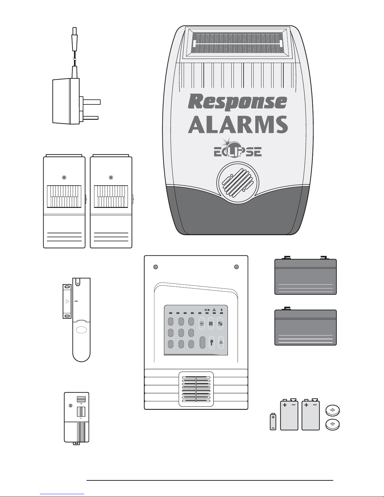
The items included in your E400 package are shown
opposite.
EXTENDING THE ECLIPSE
E400 SYSTEM
The following additional accessories are available to
enhance your system and provide further protection
and a higher level of security where required.
Part No Description
CA2000P Wirefree Passive Infra Red Detector
CA2000M Wirefree Magnetic Contact Detector
CA2000R Remote Control Unit
E100D Dummy External Siren
2 Eclipse E400
ZONE
1234ON
12
3
45
6
789
0
WP1.2-12
WP1.2-6
Detector and Remote
Control Batteries
Also included:
Installation and Operating Manual
All necessary fixings
Window warning stickers
External Solar Siren & Strobe
Control Unit
Rechargeable Batteries
(Supplied fitted in the Control Unit
and Solar Siren & Strobe)
Control Unit
Mains Adaptor
2 x Wirefree Passive Infra Red
Movement Detectors (PIRs)
Wirefree Magnetic
Contact Detector
PANIC
ON OFF
Wirefree Remote
Control
3Eclipse E400
For even greater protection you can install as many
Passive Infra Red Movement Detectors and Magnetic
Contact Detectors as and when you require. The E400
Alarm System is designed to give you protection for a
three bedroomed house. Just add additional detectors
where further protection is needed.
PART ARM
Protect either all of your home or just the areas you
choose. For example, for night time protection you can
have downstairs plus the garage and shed ‘ON’ whilst
upstairs is ‘OFF’. This allows you to occupy upstairs
areas without activating your alarm.
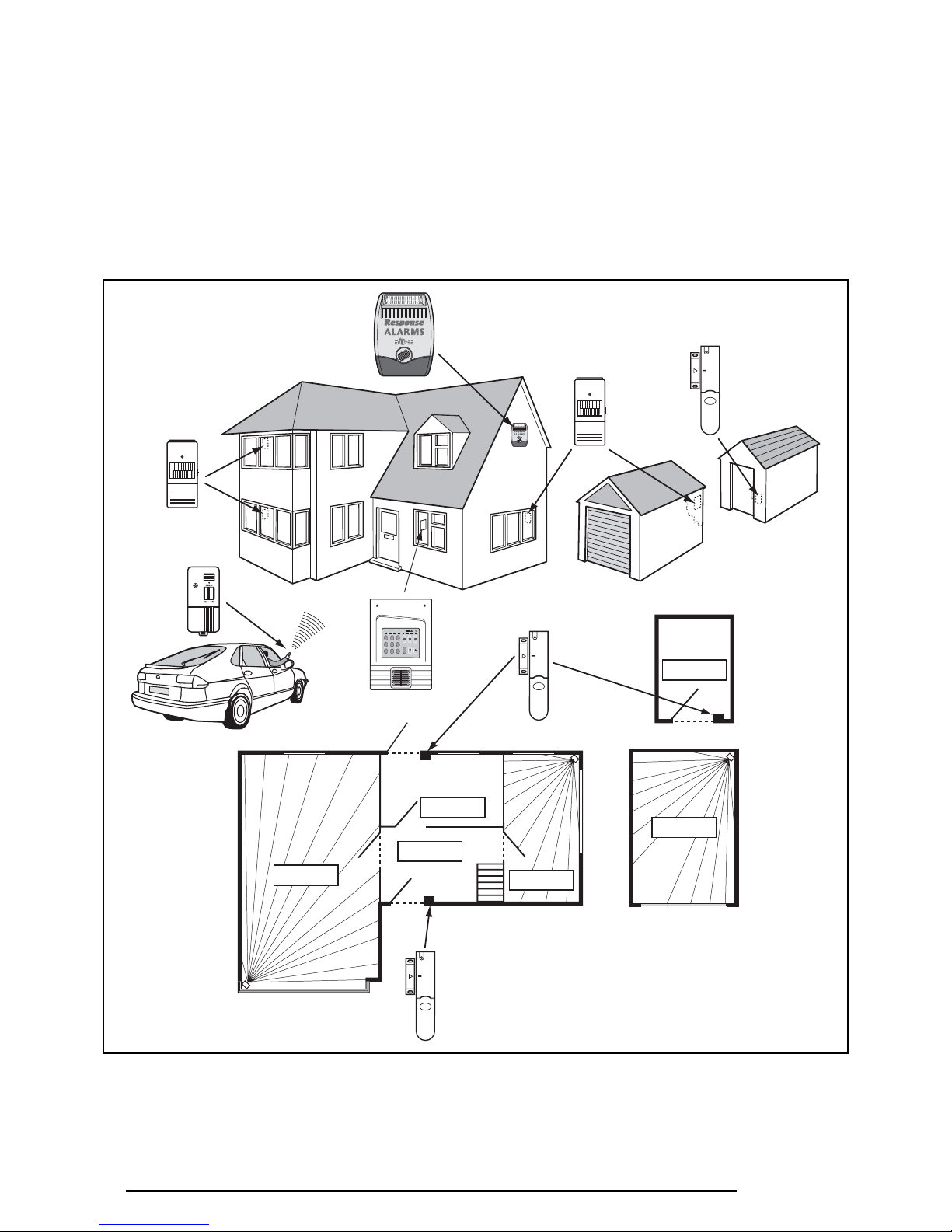
PLANNING AND EXTENDING YOUR ECLIPSE E400
ALARM SYSTEM
PLANNING YOUR INSTALLATION
Before attempting to install your E400 Alarm System it is
important to study your security requirements and plan
your installation, including Zoning and Entry/Exit routes.
Each property will have its own layout, the diagrams
shown are intended only as a guide.
External Solar
Siren & Strobe
Magnetic Contact
Detector
Remote
Control
PIR Movement
Detector
PIR Movement
Detector
LOUNGE
GROUND FLOOR
GARAGE
KITCHEN
HALL
DINNING
ROOM
Back Door
SHED
ZONE 1
ZONE 2
ZONE 2
ZONE 2
PIR
Movement
Detector
PIR
Movement
Detector
ZONE 3
ZONE 4
PIR Movement
Detector
Magnetic Contact
Detector
Magnetic Contact
Detector
Control Unit
ZONE
1234ON
12
3
4
5
6
789
0
4 Eclipse E400
LOCATION
When choosing a suitable location for the Control Unit,
the following points should be considered.
1. Ensure that the Control Unit is within a protected
area with the system Armed, ie. an intruder cannot
reach the Control Unit without opening a protected
door or being detected by a movement detector.
2. The position selected must be within reach of a
13A socket.
3. The Control Unit should be close to the Entry/Exit
door but not visible from the door or windows.
4. Do not locate the Control Unit closer than 1 metre
to any large metallic object eg. mirrors, radiators,
fridge-freezers etc., as this may affect the radio
range.
5. Locate the Control Unit in any easily accessible
position, between 1.5 and 2 metres above floor level
and in a position where it will be seen each day.
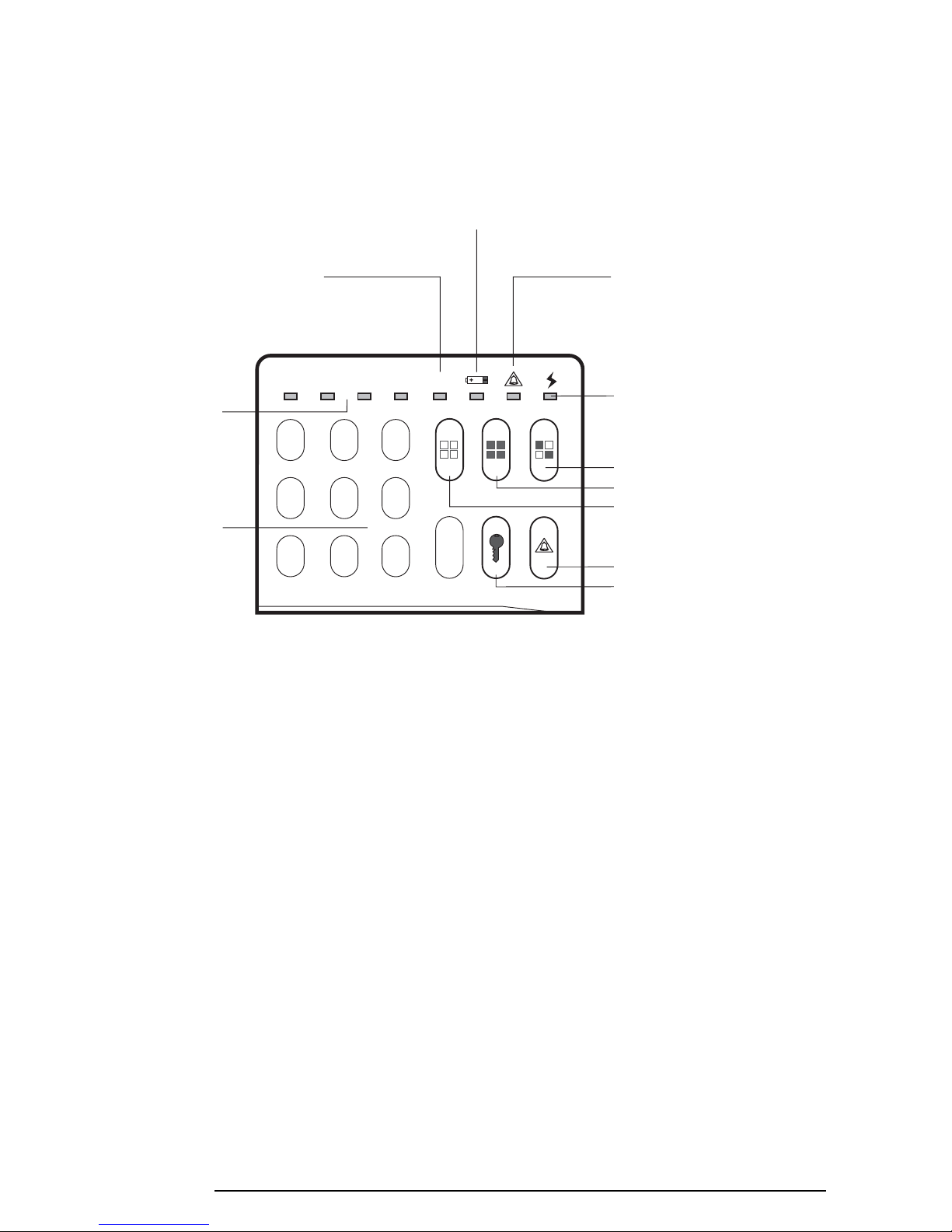
CONTROL UNIT
INDICATORS AND KEYPAD
View of Control Unit Indicators and Keypad
Detector Low
Battery LED
ZONE
1234ON
12
3
45
6
789
0
Personal Attack Button
Programme Button
Part Arm Button
Full Arm Button
Disarm Button
Power LED:
ON:- Adaptor Power (Normal)
OFF:- Battery Power Only
FLASHING:- Test/Programming Mod
e
Ta mper/Personal Attack/Zone 5
Alarm LED:
ON:- Tamper/PA Zone
Alarm Activation
FLASHING:- Hard-wired Zone 5
Alarm Activation
System Status LED:
ON:- System Fully Armed
OFF:-
System Part ArmedFLASHING:System Disarmed
Wirefree Zones 1-4
Alarm Activated
LED's
Keypad
Digits 0-9
5Eclipse E400
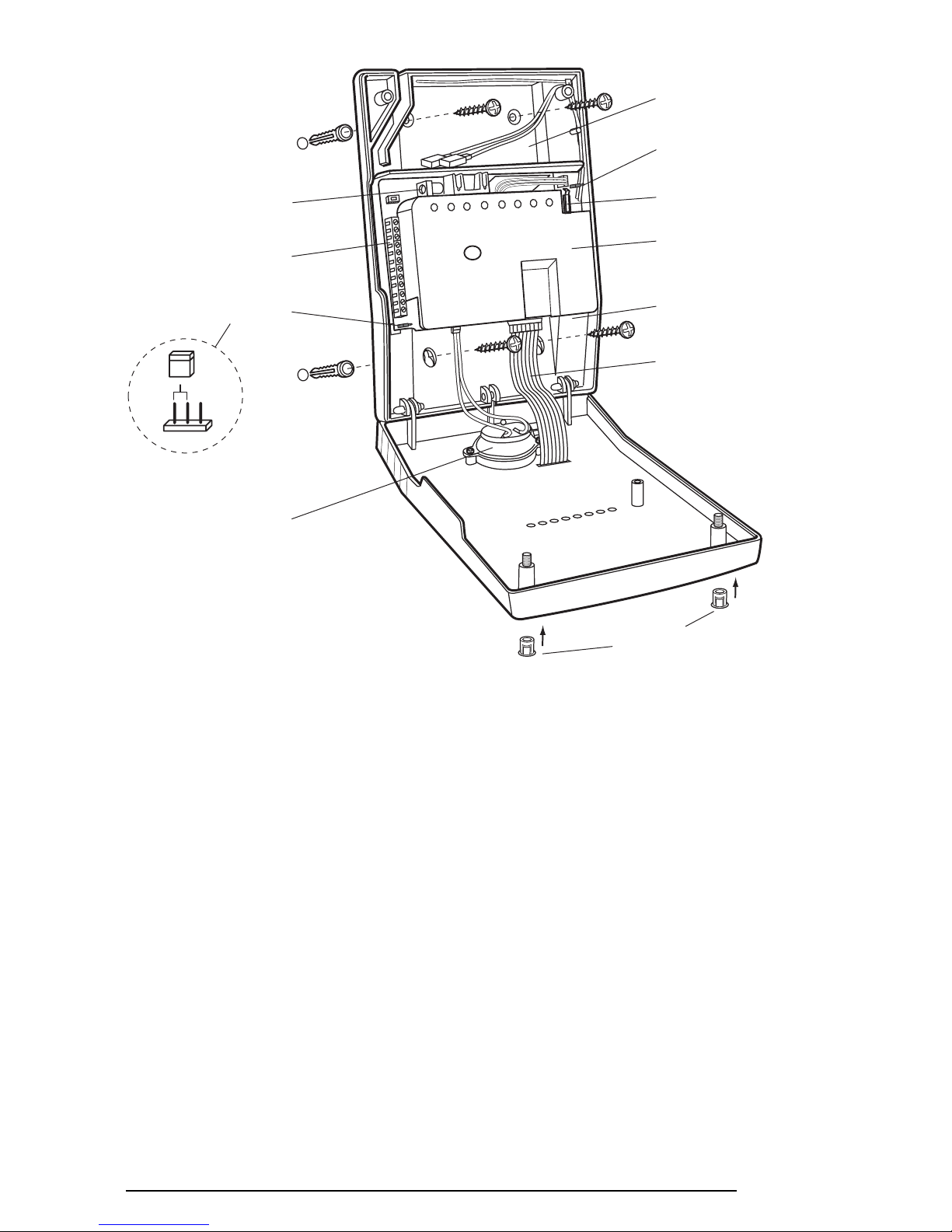
INSTALLATION
1. Undo the two front cover retaining screws and hinge
the Control Unit cover down. Remove the Control
Unit Back-up Battery.
2. Hold the Control Unit in position and mark the
four fixing holes. A small spirit level placed on top
of the Control Unit will ensure that the panel is
level. Note that the bottom fixings are keyhole
type so the holes should be marked at the top of
the keyhole.
3. Remove the Control Unit and drill four, 4mm
diameter fixing holes.
IMPORTANT NOTE: Do not drill the fixing holes
with the Control Unit in position, as the resulting
dust could seriously affect the system electronics
and invalidate the guarantee.
4. Fully insert the plastic wall plugs supplied and screw
the Control Unit to the wall using the four screws
supplied. Be careful when fitting the bottom right
hand screw not to damage the ribbon cable.
5. Ensure that the Control Unit Siren Plug is plugged
into the socket on the circuit board.
PROGRAMME MEMORY
The Control Unit incorporates a ‘Non Volatile Memory’,
which will memorise all programme settings indefinitely
even when all power has been removed. To enable this
facility to operate, the memory link must be set to the
‘ON’ position.
If, for any reason, you wish to erase the programme
memory and reset the Control Unit to the factory
settings, remove all power (mains and Back-up Battery),
set the memory link to ‘OFF’ and then re-apply power.
In all other circumstances the memory link should be
left in the ‘ON’ position.
Back-up Battery
Compartment
Hard-wired Siren Tampe
r
Return Link
Control Unit
Anti-Tamper Switch
PCB Protection
Cover
Control Unit
Siren Plug
Ribbon Cable
Screw Cover
Plu
g
s
Power Jack Socket
Terminal Block
(See page 18 for details)
Memory Link
ON
Control Unit Siren
View of Inside
of Control Unit
6 Eclipse E400
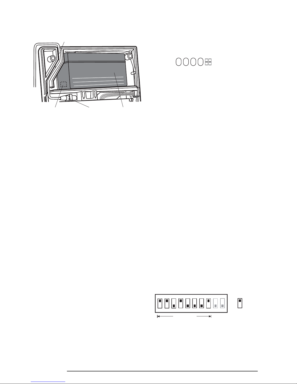
MAINS ADAPTOR AND BACK-UP
BATTERY
A DC Mains Adaptor and cable and 1.2Ahr rechargeable
Back-up Battery are supplied with the E400 equipment.
The purpose of the battery is to supply emergency
power to the Control Unit in the event of a failure of the
mains supply. The Back-up Battery is capable of
providing emergency power to the Control Unit for a
period of approximately 24 hours and will automatically
recharge on restoration of the supply. To fit the mains
adaptor and battery, proceed as follows.
1. Lead the cable along the cable track or pass the
cable through the knockout in the rear of the casing.
2. Plug the jack plug into the jack socket on the printed
circuit board as shown.
3. Plug the adaptor into a 13A socket.
4. The Control Unit will emit a bleep and the green
power indicator will now illuminate steadily,
indicating that the Control Unit is powered from the
mains supply. (It is normal for the mains adaptor to
appear warm to the touch when in use).
5. To fit the Back-up Battery, place the battery in the
compartment provided and connect the battery
leads red to red (+) and black to black (-).
6. In the event of mains failure the green power
indicator will now extinguish warning that the
Control Unit is powered by battery only.
Note: pressing any button on the Control Unit
Keypad, or Arming/Disarming from the Remote
Control will cause the power indicator to reilluminate for approximately 10 seconds and then
extinguish whilst on Back-up Battery power.
7.
Close the Control Unit cover and hold it firmly closed
whilst securing the two retaining screws. Fit the screw
cover plugs supplied to cover the retaining screws.
Note: if you accidently trigger the Control Unit Anti-
Tamper Switch whilst closing the cover,
Enter to cancel the alarm.
EXTERNAL CONNECTIONS
The Control Unit incorporates a terminal block to
facilitate external connection of a Hard Wired Siren,
Te lephone Dialler or a Hard Wired Zone 5 Trigger input.
If any Hard-wired connections are to be made at the
Control Unit it is recommended that these are made
AFTER the initial installation and programming of the
Control Unit.
For details of making external connections to the
Control Unit, see page 17.
SYSTEM HOUSE CODE
In order to prevent any unauthorised attempt to activate
or disarm your system, you must set your system to
accept encrypted radio signals only from your own
detector(s) and Remote Control Unit(s). This is done by
setting a series of two position miniature switches in the
detectors and Remote Control Unit(s) to a special
combination (House Code) selected by yourself and
programming the Control Unit to recognise only this
House Code combination.
IMPORTANT: In order for all detectors, Remote
Control Unit(s) and accessories to communicate
with the Control Unit, it is essential that the same
House Code combination is used for all components.
(Except the Solar Siren & Strobe which has a separate
Siren Code).
Inside your Remote Control(s) and detectors you will
find a series of two position miniature switches. Your
WP1.2-12
Cable Track
Alternative Cable
Entry Knockout
Power Supply
Jack Socket
12 Volt 1.2 Ahr
Rechargeable
Back-up Battery
Switch 1
set to the
ON position
e.g.
(Always change from
the factory setting)
ON
1 2 3 4 5 6 7 8 9 10
House Code
Note: Miniature switches 9 and 10 control the system
zones and DO NOT form part of the House Code
1234
7Eclipse E400
 Loading...