

Page 1
CA2000P - Wirefree PIR
Movement Detector
Installation and Operating Instructions
These instructions should be read in conjunction
with your system Installation and Operating
Manual and retained for future reference.
Introduction
The CA2000P Passive Infra Red (PIR) Movement Detector
is designed for use with all Response 418MHz, 8 dip
switch House Code, Part Wired, Wireless and Wirefree
alarm systems.
Any number of PIR Movement Detectors can be used with
your system, providing they are all coded with the System
House Code and are within the radio range of the System.
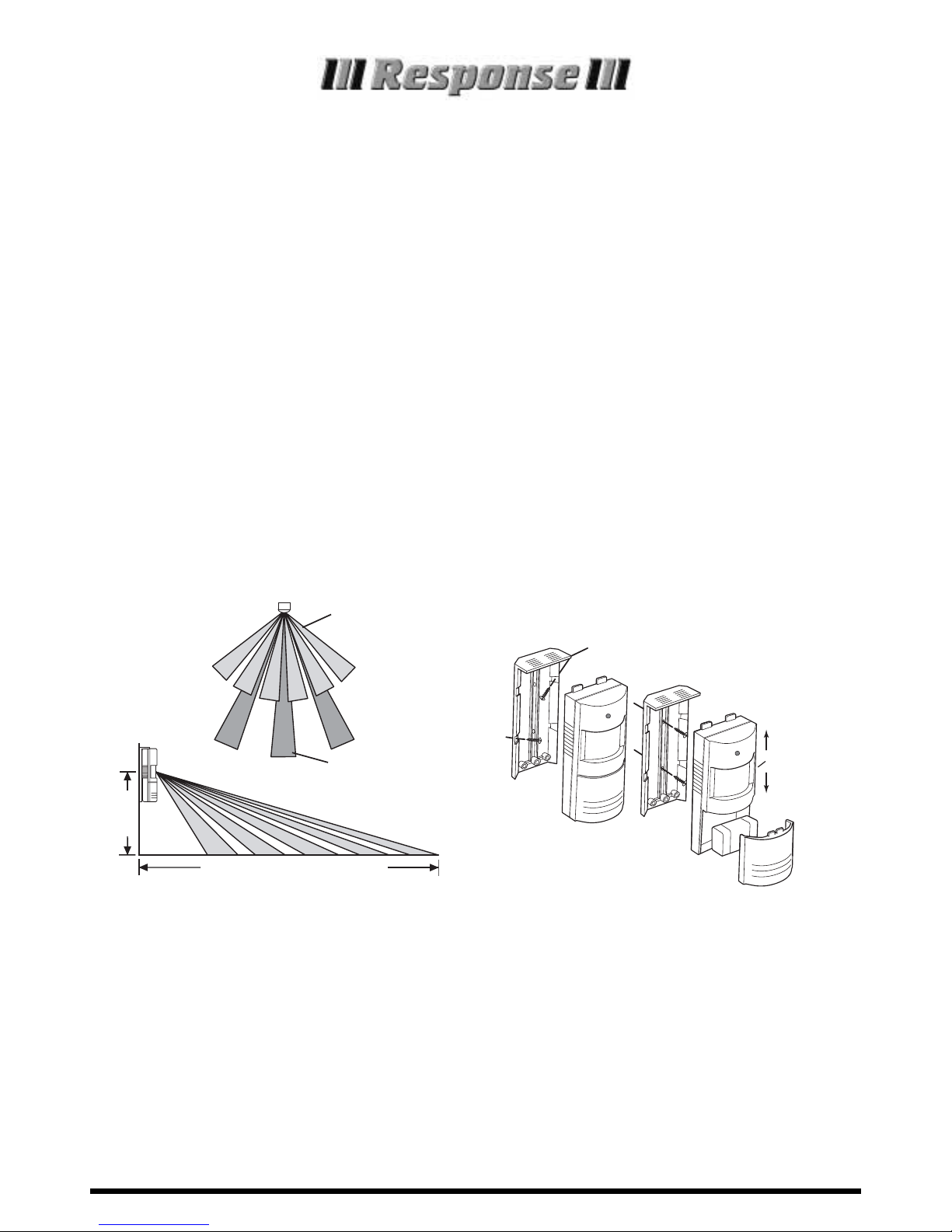
Siting
The recommended position for a PIR Movement Detector
is in the corner of a room mounted between 2 and 2.5
metres from the floor. At this height, the detector will
detect movement up to 6 metres at 110° and 12 metres at
60°, depending on adjustment. Also, in this position, the
110°/60° fan-shaped detection patterns can normally offer
greater protection than mounting on a flat wall. Before
selecting a position for a PIR Movement Detector the
following points should be noted:
1. Do not position detector facing a window or direct
sunlight.
PIR Movement
Detectors are not suitable for
use in conservatories or draughty areas.
2. Do not position detector directly above any source of
heat, eg. fire, radiators, boiler etc.
3. Where possible, keep pets out of areas protected by
PIR Movement Detectors. If this is not possible,
alternative mounting arrangements may be required.
4. Where possible, mount the detector so that the logical
path of an intruder would cut across the fan pattern
rather than directly towards the detector.
Installation and Operation
Note: Before commencing installation of the detector you
should set your system to Test mode/Service mode (refer to
your system Installation and Operating Manual for details).
1. Remove the battery cover by inserting a coin under the
cover lip and twisting open. Remove the fixings pack.
2. Remove the screw (in the battery compartment)
holding the wall bracket to the detector.
3. Slide the wall bracket up and remove the bracket from
the detector as shown.
4. Hold the wall bracket in position and mark the two
mounting holes. (If corner mounting drill pilot holes in
the chamfers as shown).
5. Drill two 4mm diameter holes and insert the plastic
wall plugs supplied.
11
0° angle
60° angle
Up to 6m at 110° and 12m at 60°
2-2.5m
Pulse Count
Detection
Switch on
Side
ON = 2
pulse
detection
OFF = 1
pulse
detection
TOP
TOP
Fixings for
Corner Mounting
Fixings for
Surface Mounting
Page 2
WA_08.04 CA2000P
Wireless Alarms. 17Church Road, Great Bookham, Surrey KT23 3PG
Telephone: 01372 450960 E-mail: info@wireless-alarms.net www.wireless-alarms.net
0359
RADIO DEVICES FOR USE IN THE UK
HELPLINE
If you need help, just dial for
expert technical support
01372 450960
(Lines open 9.00am to 6.00pm, Monday to Friday).
6.
Screw the bracket to the wall using the screws supplied.
7. Offer the detector up to the wall bracket and locate it into
one of the bracket slots to angle the detector down
slightly. Fix the detector in position on the bracket using
the fixing screw at the rear of the battery compartment.
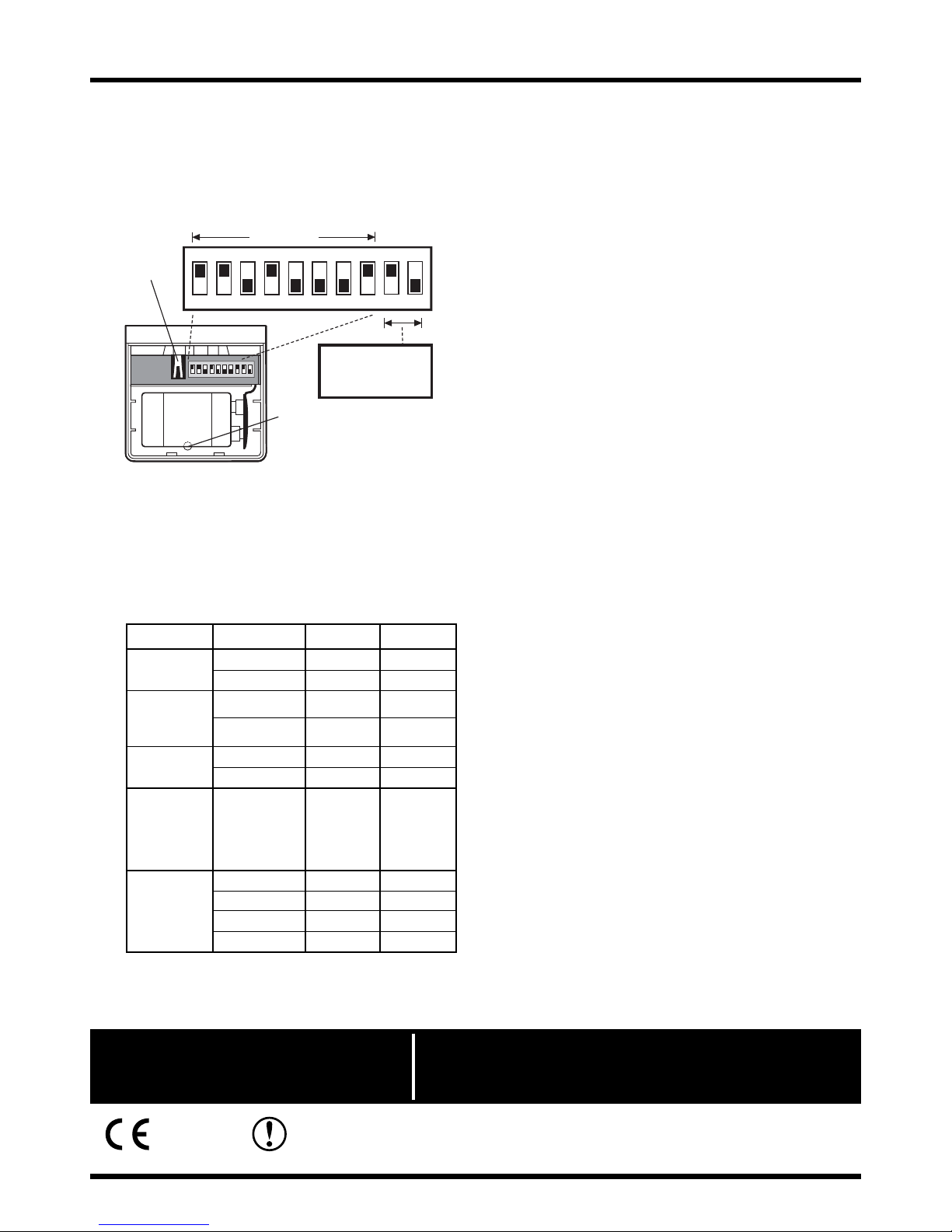
View inside PIR Movement Detector Battery Compartment
8. Using a ball-point pen, set the miniature switches 1 - 8
to the same combination of ‘ON’ and ‘OFF’ as the House
Code switches in the other items in your system.
9. Set switches 9 and 10 to suit your system/zoning as
applicable:
10. The detector incorporates an anti false alarm feature
designed to compensate where the detector may be
affected by environmental changes, eg. insects, air
temperature, etc. This feature is called ‘Pulse Count’
and may be selected for one or two pulses.
The recommended pulse count is one. In cases of
extreme environmental problems or if unattributable
false alarms are experienced, it may be necessary
to select Two Pulse Count Detection.
Note: The higher the pulse count, the more paces an
intruder will have to move before triggering the alarm.
To select the required pulse count move the switch
on the side of the detector:
UP = Two Pulse Detection
DOWN = One Pulse Detection
11. Fit the 9 Volt Alkaline battery supplied to the battery
terminals but do not replace the battery cover.
Note: Where applicable, the alarm will sound on
‘Test’ for approx. five seconds to indicate that the
House Code is correct and that the detector is
within radio range of the Control Unit.
After the battery has been connected for approx.
40 seconds the infra red detector will become
active causing the LED above the detector window
to flash every time movement is detected. Where
two pulse count detection has been selected the
LED will be dim on the first detection and brighter
on the second.
12. By walking into the protected area the detector will
now be triggered each time the detector senses
movement and the LED will flash. If necessary readjust the detection distance by angling the
detector up or down on its wall bracket.
13. Replace the battery cover on the detector.
Note: When the detector is fully installed, ie. battery
cover is fitted, the unit will not detect movement for
approx. 40 seconds after each activation. In normal
operation, with the battery cover on, the detector
LED will
not flash on movement detection.
14. Take the system out of Test/Service mode (refer to
your Installation and Operating Manual for details).
15. Arm the system and test the PIR Movement
Detector for satisfactory operation.
House Code
ON
1 2 3 4 5 6 7 8 9 10
ZONE SETTINGS
Switches 9 and 10
(see below)
Anti
Ta mp e r
Switch
Backplate Fixing Screw
ON
1 2 3 4 5 6 7 8 9 10
Installation and Operating Instructions - continued
System Zone Switch 9 Switch 10
HA50
Instant ON OFF
Delay ON ON
Protector
P400
Instant/Full Arm ON OFF
P500
Delay/Part Arm ON ON
P500S
CA610 Zone 1 ON OFF
WA510 Zone 2 ON ON
E100
E200
S100
S200
N/A ON OFF
SA1
SA2
Zone 1 ON ON
E400
Zone 2 ON OFF
S400
Zone 3 OFF ON
Zone 4 OFF OFF
 Loading...