

Page 1
®
®
®
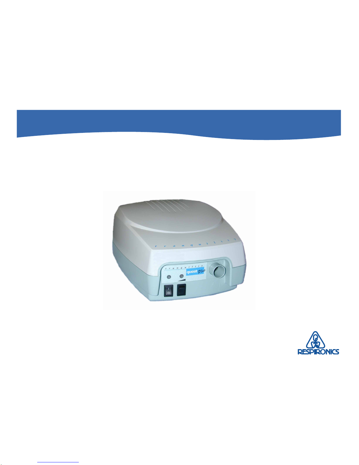
Tranquility Quest Plus
Service Manual
®
Page 2

Tranquility Quest Plus CPAP System Service Manual
Tranquility Quest® Plus CPAP System is patent pending.
Copyright © 2000 Respironics, Inc. All rights reserved.
Page 3

Tranquility Quest Plus CPAP System Service Manual
1003740
Limited Warranty
Respironics warrants that the Tranquility Quest Plus CPAP System shall be free from defects of workmanship and materials and will
perform in accordance with the product specifications for a period of two years from the date of sale by Respironics. If the product fails
to perform in accordance with the product specifications, Respironics will repair or replace—at its option—the defective material or part.
Respironics will pay customary freight charges from Respironics to the dealer location only. This warranty does not cover damage
caused by accident, misuse, abuse, alteration, and other defects not related to materials or workmanship.
Respironics disclaims all liability for economic loss, loss of profits, overhead, or consequential damages which may be claimed to arise
from any sale or use of this product. Some states do not allow the exclusion or limitation of incidental or consequential damages, so the
above limitation or exclusion may not apply to you.
This warranty is given in lieu of all other express warranties. In addition, any implied warranty, including any warranty of
merchantability or fitness for the particular purpose, is limited to two years. Some states do not allow limitations on how long an
implied warranty lasts, so the above limitation may not apply to you. This warranty gives you specific legal rights, and you may also
have other rights which vary from state to state.
The warranty for repairs is 90 days for labor and one year on the part(s) that was replaced.
To exercise your rights under this warranty, contact your local authorized Respironics dealer or contact Respironics at:
Visit Respironics Home Page on the World Wide Web at:
www.respironics.com
Page 4

Table of Contents
Tranquility Quest Plus CPAP System Service Manual
1003740
Table of Contents
Chapter 1: Warnings, Cautions,
and Notes
1.1 Warnings ....................................................... 1
1.1.1 Safety ............................................................. 1
1.1.2 Operational ................................................... 1
1.1.3 Service ........................................................... 2
1.1.4 Cleaning ........................................................ 2
1.2 Cautions ........................................................ 2
1.3 Notes ............................................................. 3
Chapter 2: Specifications
2.1 Specifications................................................ 4
Chapter 3: Theory of Operation
3.1 Functional Description ............................... 5
3.2 Block Diagram.............................................. 6
Chapter 4: System Setup
Procedures
4.1 Pressure and Ramp Settings....................... 7
Chapter 5: Routine Maintenance
5.1 Cleaning the System.................................... 8
5.2 Cleaning / Replacing the
Intake Filters................................................. 8
5.3 Preventive Maintenance Schedule
(Factory Recomended)................................ 9
Chapter 6: Troubleshooting
6.3 Troubleshooting Table ................................... 10
Chapter 7: Repair & Replacement
7.1 Service Notice............................................. 16
7.2 Technical Support Statement ................... 16
7.3.1 System Exploded View ............................. 17
7.4 Repair Kits .................................................. 18
7.5 Repair Identification Photo’s ................... 22
Chapter 8: Testing
8.1 System Final Test ....................................... 27
8.2 System Final Test Data Sheet ................... 29
8.3 Clinical Remote Control Testing
(Optional).................................................... 30
8.4 Clinical Remote Control Test Data Sheet
(Optional).................................................... 31
Page 5

Table of Contents
Tranquility Quest Plus CPAP System Service Manual
1003740
Appendix A: Tools and Equipment
A.1 Service Tools and Supplies....................... 32
A.2 Acceptable Test Equipment...................... 32
A.2.1 Digital Manometer .................................... 32
A.2.2 Digital Multimeter ..................................... 33
Appendix B: Schematics
B.1 Schematic Statement ................................. 34
B.2 Main Printed Circuit Assembly
(PCA)........................................................... 35
Table of Contents (Continued)
Page 6

Chapter 1: Warnings, Cautions, and Notes
Tranquility Quest Plus CPAP System Service Manual
1
1003740
Chapter 1: Warnings, Cautions,
and Notes
WARNING: Indicates the possibility of injury to the patient,
operator, or technician.
CAUTION: Indicates the possibility of damage to the device.
NOTE: Places emphasis on an operating characteristic.
1.1 WARNINGS
1.1.1 Safety
• This device is intended for adult use only.
• This device is not intended for life support or life
sustaining applications.
• The instructions in this manual are not intended to
supersede established medical protocols.
1.1.2 Operational
• This warning applies to most Continuous Positive
Airway Pressure (CPAP) devices. At low CPAP
pressures, the air flow through the exhalation port
may not be enough to clear all of the exhaled gas
(CO2) from the mask. You may breathe in some of
the air that you have exhaled.
• If oxygen is used with this device, the oxygen flow
must be turned off when the device is turned off. If
the device’s air flow is turned off and the oxygen
flow is left on, oxygen may accumulate in the
Tranquility Quest Plus CPAP System enclosure and
may create a risk of fire. This warning applies to
most types of CPAP devices.
• When supplemental oxygen is used at a fixed flow
rate, inhaled oxygen concentrations will vary
depending on pressure settings, patient breathing
patterns, mask selection, and leak rate.
• Oxygen supports combustion. Do not use oxygen
in the presence of open flames, cigarette smoke,
electrical spark, or other sources of ignition.
• This device is not suitable for use in the presence of
a flammable anesthetic mixture with air or with
oxygen or nitrous oxide.
Page 7

Chapter 1: Warnings, Cautions, and Notes
Tranquility Quest Plus CPAP System Service Manual
2
1003740
• In situations where risk of contamination between
the user and the device is high (e.g.: sleep lab
devices; rental devices; users with respiratory
infections), a low-resistance, main flow bacteria
filter should be placed in-line between this device
and the circuit.
• Most CPAP devices have the potential to induce
rebreathing of exhaled air. To reduce this potential,
use only Respironics circuit accessories, do not
wear the mask and headgear for more than a few
minutes while the unit is not operating, and do not
block or try to seal the vent holes in the exhalation
port.
1.1.3 Service
• Electronic components used in this device are
subject to damage from static electricity. Repairs
made to this device must be performed only in an
antistatic, Electro-Static Discharge (ESD) protected
environment.
• To assure the safety of the service technician and
the specified performance of the device,
Respironics recommends that only technicians
having prior training or experience servicing
ventilatory devices perform any repairs or adjustments to the Tranquility Quest Plus.
• High voltages are present inside this device. To
avoid electrical shock, disconnect the electrical
supply before attempting any repairs on the device.
1.1.4 Cleaning
• To avoid electrical shock, disconnect the electrical
supply before cleaning the Tranquility Quest Plus.
DO NOT immerse this device into any fluids.
1.2 CAUTIONS
• Federal law (U.S.) restricts this device to sale by, or
on the order of, a physician.
• Care should be taken to avoid exposure of the
Tranquility Quest Plus to temperatures at or near
the extremes of those specified in Chapter 2. If
exposure to such temperatures has occurred, the
device should be allowed to return to room temperature before being turned on.
• Always use an intake filter when the Tranquility
Quest Plus is in use.
• Never place liquids on or near the Tranquility
Quest Plus.
Warnings (Continued)
Page 8

Chapter 1: Warnings, Cautions, and Notes
Tranquility Quest Plus CPAP System Service Manual
3
1003740
• Discontinue using this device if any of the parts are
damaged. Replace any damaged parts before
continuing use.
• The information in this manual is provided for
service personnel reference and is not intended for
system setup or use. System setup should be
performed by appropriate personnel using Home
Care Dealer Instructions.
1.3 NOTES
• Refer to the Tranquility Quest Plus User’s Manual
for product use, additional warnings, cautions, and
notes.
Additional WARNINGS, CAUTIONS, and NOTES are located
throughout this manual.
Cautions (Continued)
Page 9

Chapter 2: Specifications
Tranquility Quest Plus CPAP System Service Manual
4
1003740
ELECTRICAL:
AC Input Voltage................................... 85 - 260VAC; 47-63Hz
AC Current Consumption .................... 1.0 A maximum
Power Consumption ............................. 75 VA maximum
Class......................................................... IIa
Type ......................................................... Type BF
RAMP:
Minimum Ramp Pressure............. 3.0 - 20.0 cm H2O
Ramp Resolution.............................. 1.0 cm H2O
Ramp Time ....................................... 0 - 30 minutes
Ramp Time Resolution ................... 5 minute increments
PRESSURE:
CPAP Pressure ....................................... 3.0 – 20.0 cm H2O
Readout Resolution ............................... 1.0 cm H20
Accuracy, Static ...................................... +1.0 cm H2O for flows between
-60 to + 120 L/min.
Accuracy, Dynamic ............................... + 1.5 cm H2O for flows between
-60 to + 120 L/min.
Chapter 2: Specifications
2.1 Specifications
ENVIRONMENTAL:
Operating Temperature ........................ 41 to 104°F (5 to 40°C)
Storage Temperature............................. -4 to 140°F (-25 to 60°C)
Humidity ................................................ 10 to 95% non-condensing
Altitude ................................................... 0 - 10,000 ft (0 - 3048 m)
Noise Level ............................................. No specification is given
because various test instruments, test procedures, and unit
operating conditions produce
varying results.
PHYSICAL:
Dimensions ............................................. 9.5” (L) x 7.75” (W) x 5.0”(H)
(24.1 x 19.7 x 5.0cm)
Weight ..................................................... 4.9 lbs (2.2 kg)
FUSE:
Fuse Type ................................................ T1A, 250v, 5 x 20 mm
(Respironics P/N 1004092)
Page 10

Chapter 3: Theory of Operation
Tranquility Quest Plus CPAP System Service Manual
5
1003740
The ramp feature lets the user reduce the pressure from the unit so
that the patient can fall asleep at a lower, more comfortable pressure
at any time or as many times as needed during the night.
The patient circuit is made up of the flexible tubing, exhalation port,
and nasal mask. The unit applies CPAP to the patient’s upper
airway to keep the airway open during the sleep. Air flow generated from the unit is directed to the patient via a mask and flexible
tubing that connects to the air outlet port of the unit.
The Tranquility Quest Plus is intended to deliver CPAP therapy
only. It is not intended for life support or life sustaining applications.
Chapter 3: Theory of Operation
3.1 Functional Description
The Tranquility Quest Plus is a microprocessor-controlled Continuous Positive Airway Pressure (CPAP) device that produces positive
pressure. The unit operates only in the CPAP Mode. CPAP Mode
pressure range: 3.0 – 20.0 cm H2O.
Integral to the generation of air flow is the blower assembly. Ambient air is drawn through the air intake filter by the energized blower
and is then pressurized. Ultimately, therapeutic pressure is provided to the patient via the patient circuit. The microprocessor
regulates the motor speed, which in turn adjusts and controls the
pressure.
The Tranquility Quest Plus’s control pad, which includes three push
buttons and an LCD display is the primary means by which the
patient therapy is controlled. Patients have limited access to unit
parameters.
The unit may be powered from AC voltage (100-240 VAC). AC
power enters the unit via an AC inlet and appropriate power cord.
The two system filters, the pollen and the ultra-fine, ensure optimum operation for the user. An air outlet port allows for connection to the patient circuit.
Page 11

Chapter 3: Theory of Operation
Tranquility Quest Plus CPAP System Service Manual
6
1003740
Tranquility Quest Plus
Main PCA
Control Pad
(3 Pushbuttons)
Air Outlet
Optical
Connection
Tranquility Quest Plus
3.2 Block Diagram
Page 12
Chapter 4: System Setup Procedures
Tranquility Quest Plus CPAP System Service Manual
7
1003740
Chapter 4: System Setup
Procedures
NOTE: This section provides directions for accessing the
Therapy Menu. Prescribed therapy settings can
only be set using the Therapy Menu. (To prevent
patients from tampering with the settings, the
directions to access the Therapy Menu should not
be revealed to the patient.)
CAUTION: If the Tranquility Quest Plus CPAP System has
been exposed to either very hot or very cold
temperatures, allow it to adjust to room
temperature (approximately one hour) before
beginning setup.
4.1 Pressure and Ramp Settings
The pressure and ramp settings for the unit are set using the
Control Panel on the bottom of the unit. When not in use the
Control Panel display will show the current compliance meter
reading for the unit. This reading will reflect the total number of
hours that the patient has been breathing on the unit.
With the unit turned on and looking at the bottom, press the up
and down arrow button simultaneously for three seconds and the
pressure and ramp setting will be displayed. The Minimum
Pressure setting will now be flashing. Press the up or down arrow
button to change the setting. Press the mode button to move to the
ramp setting. Press the up or down arrow button to change the
setting. The setting is implemented immediately when the up or
down button is pressed. Press the mode button for three seconds
to lock the controls.
The display will revert to the compliance meter display 60 seconds
after the last time a button has been pushed. The settings can only
be changed if they are flashing, otherwise they are locked.
Page 13

Chapter 5: Routine Maintenance
Tranquility Quest Plus CPAP System Service Manual
8
1003740
Chapter 5: Routine Maintenance
5.1 Cleaning the System
WARNING: To avoid electrical shock, disconnect the electrical
supply before attempting to clean the Tranquility
Quest Plus. DO NOT immerse the unit in water or
allow any liquid to enter the cabinet or the filter
intake.
Wipe the outside of the unit with a cloth slightly
dampened with water and a mild detergent. Let the
unit dry before reconnecting the electrical supply.
5.2 Cleaning / Replacing the
Intake Filters
The gray pollen filter is a reusable filter that screens out pollens and
some household dust. This filter should be cleaned at least once
every two weeks under normal usage, or as required, and replaced
with a new one every six months. The pollen filter must be in place
at all times when the unit is operating.
The disposable white ultra-fine filter increases filtration of pollens,
dust, some tobacco smoke, and small particles. The ultra-fine filter
is included with the system, but is optional and should be used in
addition to the pollen filter. The ultra-fine filter should never be
used without the pollen filter. Replace the ultra-fine filter after 30
nights of use or sooner if it appears dirty. DO NOT clean the ultrafine filter.
CAUTION: Failure to replace a dirty filter may cause the device
to operate at higher then normal temperatures and
damage the device.
CAUTION: The pollen filter must be completely dry before
use. Never place a wet filter into the device.
Respironics recommends that you clean the filter in
the morning and alternate using the two pollen
filters provided with the system to ensure enough
drying time for the cleaned filter.
Page 14

Chapter 5: Routine Maintenance
Tranquility Quest Plus CPAP System Service Manual
9
1003740
Tranquility Quest Plus CPAP System Preventive Maintenance Schedule (Continued)
5.3 Tranquility Quest Plus Preventive Maintenance Schedule (Factory Recommended)
Model No. _____________ Serial No. ______________________ Date____________ Service Technician ________________
Maintenance Item Verification Reference Service Interval Date
Record hours of Display As desired
compliance
Replace Pollen filter Section 5.2 Clean every two weeks, or as
required;
Change every six months
Replace Ultra-fine filter Section 5.2 Replace after 30 nights of
(if used) use (sooner if it appears dirty)
Perform Testing Process Section 8.1 After service is performed
Cleaning Section 5.1 As required
Page 15

Chapter 6: Troubleshooting
Tranquility Quest Plus CPAP System Service Manual
10
1003740
6.1 Troubleshooting Table
Symptom Cause Verification Corrective Action
Indicator -
LED or other indicator not
working.
LED / Main PCA
Visual
Replace Main PCA
Replace in order until
solved:
• Display PCA
• Main PCA
Ribbon Cable
Intermittent Power Supply
Problem -
An intermittent on / off
condition exists, unit operates
randomly, or indicator
lights blink sporadically.
• Power cord, AC inlet,
Main PCA, loose
connections.
• Power Supply PCA.
Inspect power cord. Inspect
all connectors on
the PCAs.
• Power Cord
• Power Supply PCA
Display -
Display is blank or contains
erroneous information. Unit
delivers therapy pressure.
• Display assembly
• Main PCA
Inspect the cable between
the display and the main
control board for loose
connection.
Page 16

Chapter 6: Troubleshooting
Tranquility Quest Plus CPAP System Service Manual
11
1003740
Odor -
Noise -
Turn unit over and inspect
the bottom for missing or
damaged rubber feet.
Troubleshooting Table (Continued)
Symptom Cause Verification Corrective Action
Missing or damaged rubber
foot on bottom of unit,
blower malfunctioning.
Replace Blower.
Tubing smells new, unit
smells new, airborne residue
buildup.
Visually inspect patient
tubing for contamination.
Run unit in a clean environment for a few hours to
eliminate new smell. Wash
tubing with soap and water.
To clear residue build-up,
replace all subassemblies in
the patient air stream
(blower, filters, patient
circuit).
Page 17

Chapter 6: Troubleshooting
Tranquility Quest Plus CPAP System Service Manual
12
1003740
Troubleshooting Table (Continued)
Outlet air temperature -
The outlet air temperature is
too warm.
Filters dirty, blower, Main
PCA.
Ensure the filter is clean
and not restricting air flow.
Monitor the outlet air temperature at the end of the
six foot tubing. A rise in
temperature can be expected.
Ensure the unit is not next to
any heat source.
Symptom Cause Verification Corrective Action
Replace in order until solved:
• Filter(s)
• Blower
• Main PCA
Pressure Related Problems -
The outlet pressure does not
change or properly adjust.
Pressure tubing has been
blocked, disconnected, or
kinked. Main PCA or
blower malfunction.
Inspect pressure tubing for
secure connections and
kinks. Check blower for air
leaks.
• Secure pressure tubing
connections.
• Replace blower, pressure
tubing, or Main PCA as
required.
Page 18

Chapter 6: Troubleshooting
Tranquility Quest Plus CPAP System Service Manual
13
1003740
Pressure Offset -
Static pressure fluctuates
Troubleshooting Table (Continued)
The delivered pressure is
higher or lower than the set
value by more than the
specification
Perform power up process
and check again.
• Check tubing for kinks.
• Replace the Main PCA.
• Replace the Main PCA.
Symptom Cause Verification Corrective Action
Ramp LED Flashing
Device not calibrated
Unable to turn unit on.
Replace the Main PCA.
Page 19

Chapter 6: Troubleshooting
Tranquility Quest Plus CPAP System Service Manual
14
1003740
Ramp Pressure -
The pressure does not ramp
correctly.
Troubleshooting Table (Continued)
• No ramp time prescribed.
• Main PCA.
• Ramp button not
functioning.
Make sure the patient's
prescription specified
ramp. Make sure unit was
set for ramp.
Set unit for ramp.
Replace Main PCA.
Pressure Variation - The
pressure varies around the
set value, pressure fluctuates
greater than 1 cm H
2
O.
• Internal air leak
• Filters dirty
• Main PCA, Blower
• Air path blocked
Replace filters
Perform Testing Process
(see Section 8.1)
Replace Blower.
Replace Main PCA
Symptom Cause Verification Corrective Action
Compliance Meter Not
Updating
Main PCA
Time not updating.
Replace Main PCA
Page 20

Chapter 7: Repair & Replacement
Tranquility Quest Plus CPAP System Service Manual
15
1003740
Chapter 7: Repair
Information
7.1 Service Notice............................................ 16
7.2 Technical Support ..................................... 16
7.3 Tranquility Quest Plus CPAP System
Exploded View.......................................... 17
7.4 Tranquility Quest Plus CPAP System
Repair Kits ................................................. 18
7.5 Repair Identification Photo’s .................. 22
Page 21

Chapter 7: Repair & Replacement
Tranquility Quest Plus CPAP System Service Manual
16
1003740
7.1 Service Notice
This service manual was prepared by Respironics primarily for use
by technicians to service the Tranquility Quest Plus System. The
individuals using this manual to service the Tranquility Quest Plus
system should have prior training or experience servicing
ventilatory devices.
7.2 Technical Support
Respironics is committed to customer satisfaction and may be
contacted with any questions or for technical support. For technical
assistance or replacement part ordering information contact:
U.S. and Canada - Customer / Technical Service
Phone: 1-800-345-6443
Fax: 1-800-886-0245
International- Customer / Technical Service
Phone: 001-412-731-2100
Fax: 001-412-473-5012
Visit Respironics Home Page on the World Wide Web at:
www.respironics.com
Page 22

Chapter 7: Repair & Replacement
Tranquility Quest Plus CPAP System Service Manual
17
1003740
Tranquility Quest Plus CPAP System Exploded View
7.3 Tranquility Quest Plus CPAP System
Exploded View
Top Enclosure
Blower Assembly
(Plastic or Aluminum)
Outlet Port
Power Supply
Standoffs
Heat Sink
Display Assembly
Main PCA
Display Cable
Bottom Enclosure
Chassis Mounting Plate
Blower Vibration Isolator
AC Inlet
Hose (Blower to Flowmeter)
Ramp Switch Wire Harness
Power Supply
Mounting Plate
Page 23

Chapter 7: Repair & Replacement
Tranquility Quest Plus CPAP System Service Manual
18
1003740
7.4 Tranquility Quest Plus CPAP System Repair Kits
Replacement Part Replacement Part No. Illustration
AC Inlet 1004001 7-8
AC Power Cord See Note 1 362524 N.A.
Blower Kit - Aluminum See Note 2 1004006 7-9
Blower Kit - Plastic See Note 2 1004007 7-9
Blower Vibration Isolator (3) 1004008 7-10
Includes:
(2) Cable Ties
Bottom Enclosure 1004004 7-8
Note 1: For available international AC Power Cords, contact Respironics Customer Service.
Note 2: Blower assemblies are not interchangeable. Be sure to use the same style blower when replacing the assembly.
Page 24

Chapter 7: Repair & Replacement
Tranquility Quest Plus CPAP System Service Manual
19
1003740
Chassis Mounting Plate 1004009 7-10
Includes:
(1) Lower Chassis
(1) Foam Seal
(1) Screen Foam Cover
(3) Vibration Isolators
(1) Bottom Blower Foam Seal
(3) Standoffs M-F, 6-32 x 1/4”
(2) #6-19 x 3/8” Plastite PHP Screws
Display Assembly 1004011 7-3
Display Cable 1004013 7-3
Filter, Replacement 7301 5-2
Filter, Disposable 7302 N.A.
Front Overlay 1004093 7-7
Hose, Blower to Flowmeter 1004010 7-3
Includes:
(1) Hose
(2) Cable Ties
Tranquility Quest Plus CPAP System Repair Kits (Continued)
Replacement Part Replacement Part No. Illustration
Page 25

Chapter 7: Repair & Replacement
Tranquility Quest Plus CPAP System Service Manual
20
1003740
Key Pad 1004094 7-11
Label, Power Fuse 1004091 7-8
Label, Symbol 1004090 7-11
Main PCA ( Quest Plus Only) 1004005 7-10
Includes:
Main PCA
(2) Standoffs
(2) #4-40 x 5/8” PHP Screws
(1) #6-19 x 3/8” Plastite PHP Screw
(1) Tubing Assembly
(1) Tubing Sub-Assembly 5 3/4”
(1) Tubing Sub-Assembly 8 1/2”
Outlet Port / Flowmeter 1004003 7-8
Includes:
(1) Outlet Port
(1) #6-19 x 3/8” Plastite PHP Screw
Replacement Part Replacement Part No. Illustrations
Page 26

Chapter 7: Repair & Replacement
Tranquility Quest Plus CPAP System Service Manual
21
1003740
Power Supply 1004421 7-9
(2) #6-32 X 1/4” Screws
(2) #6-32 X 1/2” Screws
(1) Insulator
Ramp Switch Wire Harness 1004002 7-9
Rubber Feet (x4) 1004516 7-10
Service Manual 1004014 N.A.
Top Enclosure 1004095 7-8
Replacement Part Replacement Part No. Illustrations
Page 27

Chapter 7: Repair & Replacement
Tranquility Quest Plus CPAP System Service Manual
22
1003740
(Figure 2)
Top Enclosure
Fuse Drawer
Bottom Enclosure
On / Off Switch
Ramp Buttom
Outlet Port
(Figure 1)
Fiber Optic
Communication Port
7.5 Repair Identification Photo’s
Replacement Filter
AC Inlet
Power Fuse Label
(Not Shown)
Front Overlay
Page 28

Chapter 7: Repair & Replacement
Tranquility Quest Plus CPAP System Service Manual
23
1003740
Power Supply PCA
(Figure 4)
Blower Assembly
(Figure 3)
Repair Identification Photo’s (continued)
Power Supply AC Input Wire Harness
Cable Tie (through Main PC Board)
Page 29

Chapter 7: Repair & Replacement
Tranquility Quest Plus CPAP System Service Manual
24
1003740
(Figure 6)
AC Inlet
Blower Vibration
Isolator (3)
Chassis Mounting Plate
Main PCA
Repair Identification Photo’s (continued)
(Figure 5)
Heat Sink
Display Cable
Pressure Tubing
Ramp Switch Wire
Ramp Switch Wire Harness
Main Power Switch Wire Harness
Page 30

Chapter 7: Repair & Replacement
Tranquility Quest Plus CPAP System Service Manual
25
1003740
Rubber Feet (x4)
Symbols Label
Control Panel
Repair Identification Photo’s (continued)
(Figure 7)
Page 31

Chapter 8: Testing
Tranquility Quest Plus CPAP System Service Manual
26
1003740
Chapter 8: Testing
8.1 Tranquility Quest Plus System
Final Test....................................................... 27
8.2 Tranquility Quest Plus System
Final Test Data Sheet................................... 29
8.3 Clinical Remote Control Testing
(Optional) ..................................................... 30
8.4 Clinical Remote Control
Test Data Sheet (Optional) ......................... 31
Page 32

Chapter 8: Testing
Tranquility Quest Plus CPAP System Service Manual
27
1003740
8.1 Tranquility Quest Plus System
Final Test
Purpose
This procedure provides performance verification of the Tranquility
Quest Plus (Model 7400) CPAP System and the Clinical Remote
Control (Model 1703). It is to be used on each unit prior to, and
after run-in. Results to be entered on the attached Data Sheet for
each unit.
CAUTION: Electronic components used in this device are
subject to damage from static electricity. Use and
follow appropriate Electro-Static Discharge (ESD)procedures.
Equipment
• Digital Manometer
Specs:
0 - 25 cm H2O
± 0.3 cm H2O accuracy
± 0.1 cm H2O
• Port Cap or Stopper
• Pressure Tubing
• Test Orifice (RI p/n 532232) (0.38” diameter)
• DC Power Supply, Model 913*
• Optical Interface Cable* (RI P/N 1701-06)
* Used for Clinical Remote Control Testing
Equipment Setup
• Place the test orifice onto the outlet of the unit.
• Connect the manometer to the test orifice using
pressure tubing.
• Connect the AC power cord to the unit and to the
wall outlet.
Procedure
Step 1 Turn the unit on. Hold the up and down arrow buttons
in for three seconds. Set the pressure for 3 cm H2O and
the ramp to 5 minutes.
Step 2 Verify that the green LED is illuminated above the main
power switch. Record the results.
Step 3 Occlude the test orifice. Verify the pressure on the
manometer is 2.5 to 3.5 cm H2O. Record the results.
Step 4 Unocclude the test orifice. Verify the pressure on the
manometer is 2.0 to 4.0 cm H20. Record the results.
Step 5 Hold the up and down arrow buttons in for three
seconds. Set the pressure for 20 cm H20.
Step 6 Unocclude the test orifice. Verify the pressure on the
manometer is 19.0 to 21.0 cm H2O. Record the results.
Page 33

Chapter 8: Testing
Tranquility Quest Plus CPAP System Service Manual
28
1003740
Step 7 Press the ramp button and verify that the pressure on
the manometer drops to approximately 3.0 cm H20.
Pressure will increase over the specified time period
until the pressure setting is reached. Verify at least 1
cm H2O in pressure change in ramp operation.
Record the results. If necessary, turn the unit off and
then back on again to disable the ramp feature.
Step 8 Run the unit in for four hours at the 10 cm H2O
setting. Record start and stop times.
Step 9 Verify the pressure to be 9.0 to 11.0 cm H2O on the
manometer after run-in. Record the results.
Step 10 After run in, repeat steps 2 through 8 and then
proceed to step 11.
Note: Perscription pressure must be reset by authorized personel.
Tranquility Quest Plus System Final Test (Continued)
Page 34

Chapter 8: Testing
Tranquility Quest Plus CPAP System Service Manual
29
1003740
8.2 Tranquility Quest Plus System Final Test Data Sheet
Pre Run In Time and Date Post Run In Time and Date Total Run In Time
Serial Number Service Notification (RI use)
Model Number
Test Step Specification Actual Actual Final
Pre Run-In Post Run-In Pass / Fail
LED Illuminated 2 Pass / Fail
Minimum Pressure 2.5 to 3.5
Occluded 3 cm H2O
Minimum Pressure 2.0 to 4.0
Unoccluded 4 cm H2O
Maximum Pressure 6 19.0 to 21.0
cm H
2
O
Ramp 7 Pass / Fail
Pressure after Run - In 9 9.0 to 11.0
cm H2O
2345678901234567890
1
2345678901234567890
1
2345678901234567890
1
2345678901234567890
1
2345678901234567890
1
2345678901234567890
1
Tested By: (Print) Tested By: (Signature) Date
Page 35

Chapter 8: Testing
Tranquility Quest Plus CPAP System Service Manual
30
1003740
CRC Test Procedure
(Optional; to be used if CPAP unit is equipped with a CRC)
1. Using the up and down arrows on the CRC, set the pressure
control to the settings in the following table and verify that the
pressure readings on the manometer are within the specified
tolerances. Note that there will be a 3 second delay between the
pressure setting and the actual pressure change. Record the
results.
Display Setting (cm H
2
O) Pressure Reading (cm H2O)
18 17.7 to 18.3
15 14.7 to 15.3
9 8.7 to 9.3
6 5.7 to 6.3
3 2.7 to 3.3
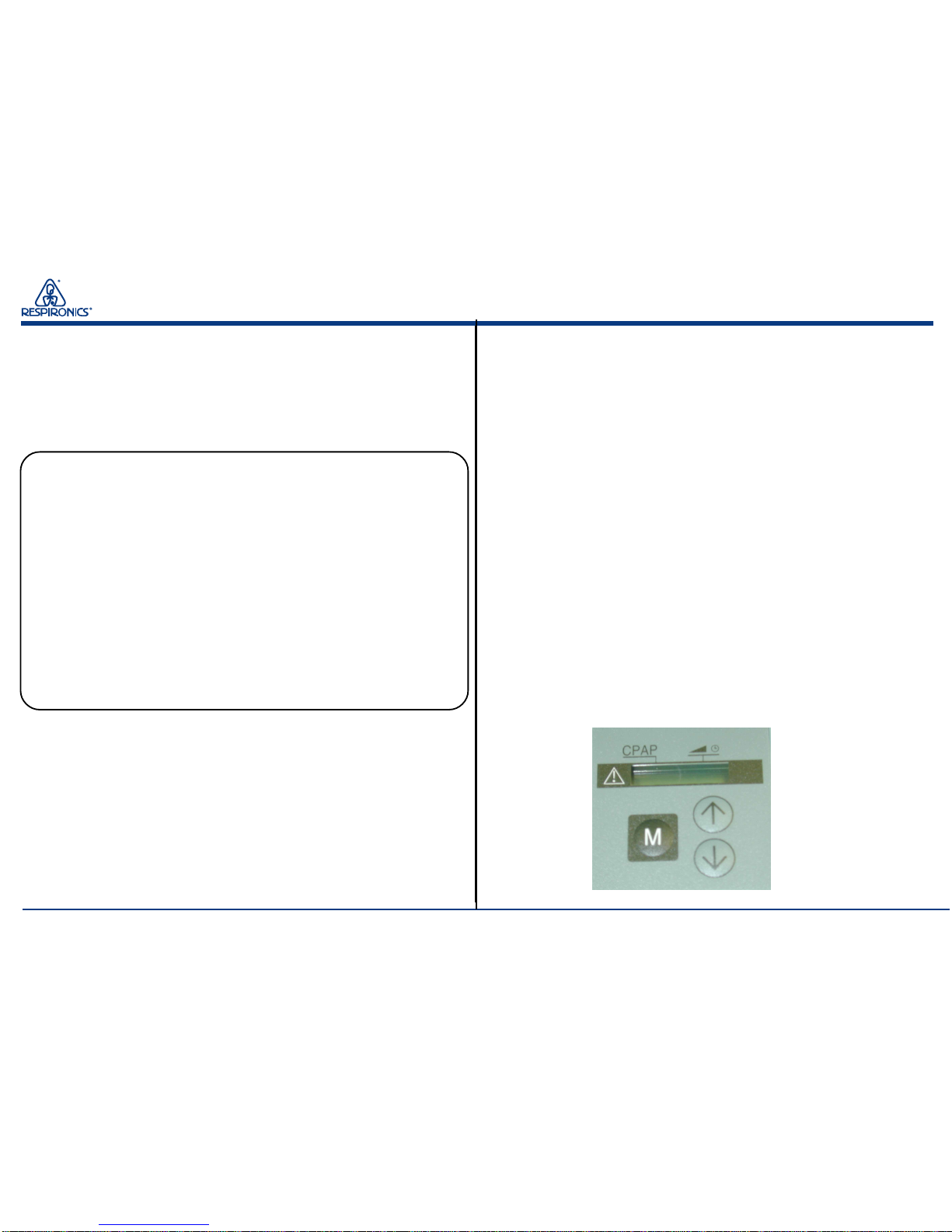
2. Set the CRC to 20 cm H2O. Press the M button twice on the CRC
to select the ramp mode. Set the ramp time to 10 minutes. Press the
ramp button on the front of the CPAP unit. Verify that the amber
LED is lit and that the pressure drops to approximately 3.0 cm H2O.
The pressure will increase over the specified time period until the
pressure setting is reached. Verify at least 1 cm H2O in pressure
change in ramp operation.
3. Turn the units main power switch off.
4. Disconnect the CPAP remote from the 7400.
8.3 Clinical Remote Control Testing
(Model 1703)
Equipment and Setup:
1. Plug the 9 VDC Power Supply into the Model 1703 Clinical
Remote Control (CRC).
2. Connect the Optical Interface cable to the CPAP unit. It will
lock into place. Turn the power onto the unit.
3. Observe which side of the optical interface plug has the red
LED.
4. Plug the optical cable into the CRC. Make sure that the red
LED’s DO NOT match up. The display on the remote will
read CPAP.
5. Connect the manometer to the occluded test orifice and the
test orifice to the unit.
Page 36

Chapter 8: Testing
Tranquility Quest Plus CPAP System Service Manual
31
1003740
8.4 Tranquility Quest Plus System Final Test Data Sheet
Clinical Remote Control (CRC)
(Optional to be used if CPAP unit is equipped with a CRC)
Serial Number Service Notification (RI use)
Model Number
Test Step Specification Actual Actual Final
Pre Run-In Post Run-In Pass / Fail
CRC Setting 17.7 to 18.3
18 cm H
2
O cm H2O
CRC Setting 14.7 to 15.3
15 cm H
2
O cm H2O
CRC Setting 8.7 to 9.3
9 cm H2O cm H2O
CRC Setting 5.7 to 6.3
6 cm H2O cm H2O
CRC Setting 2.7 to 3.3
3 cm H2O cm H2O
CRC Ramp LED
Illuminated and Ramp Pass / Fail
Operation
Tested By: (Print) Tested By: (Signature) Date
Page 37

Appendix A: Tools and Equipment
Tranquility Quest Plus CPAP System Service Manual 32
1003740
Appendix A: Tools and Equipment
A.1Service Tools and Supplies
You should have the following hand tools and supplies available for
troubleshooting, testing, and repairing the Tranquility Quest Plus
CPAP System.
• Common Hand Tools
Flat-blade screwdriver - small
Phillips screwdriver - medium
• Antistatic, Electro-Static Discharge (ESD)-protected
work station – minimum requirement is a grounded
mat and wrist strap
• Digital Manometer – see Section A.2
• Digital Multimeter – see Section A.2
•O2 Enrichment Port (RI P/N 312010)
• Test Orifice (RI P/N 532232)
• Whisper Swivel II (RI P/N 332113)
• Cleaning cloth
• Isopropyl alcohol
A.2Acceptable Test Equipment
A.2.1 Digital Manometer*
Specifications:
0 – 25 cm H2O (or better)
±0.3 cm H2O accuracy
±0.1 cm H2O resolution
Acceptable Options:
• Respironics Digital Manometer
(RI P/N 302227)
• Merical DP2001
• Sensym PDM 200CD
• RT-200
• Any commercially available digital
manometer that meets the above specifications.
* A water-column manometer may also be used.
• Mild detergent
Page 38

Appendix A: Tools and Equipment
Tranquility Quest Plus CPAP System Service Manual 33
1003740
A.2.2 Digital Multimeter
Specifications:
2.5 digit readout minimum
0.0 – 20.0 VDC
0.0 – 25.0 VAC
Acceptable Options:
• Fluke 83 or better model
• Any commercially available digital multimeter that meets the above specifications.
Page 39

Tranquility Quest Plus CPAP System Service Manual
34
1003740
Appendix B: Schematics
B.1 Schematic Statement
Schematics are supplied with this manual in direct support of the
sale and purchase of this product.
The schematics are proprietary and confidential. Do not copy the
schematics or disclose them to third parties beyond the purpose
for which they are intended. Patents are pending.
The schematics are intended to satisfy administrative requirements
only. They are not intended to be used for component level testing
and repair. Any changes of components could affect the reliability
of the device, prohibit lot tracking of electronic components, and
void warranties. Repairs and testing are supported only at the
complete board level.
The schematics are of the revision level in effect at the time that this
manual was last revised. New revisions may or may not be distributed in the future.
Note: The Power Supply PCA is a purchased item. The schematic is
not available for distribution.
Appendix B: Schematics
Page 40

Tranquility Quest Plus CPAP System Service Manual
35
1003740
B.2 Main Printed Circuit Assembly (PCA)
Page 41

Tranquility Quest Plus CPAP System Service Manual
36
1003740
B.2 Main Printed Circuit Assembly (PCA)
Page 42

Reorder # 1004014 Revision # 1003740
DS / KT 01/05/00
 Loading...