

Respironics Millennium H600, Millennium H605, Millennium M10600, Millennium M10605, Millennium Enhanced M600 Service And Technical Reference Manual
...Page 1

Millennium
TM
Oxygen Concentrators
Service & Technical Information
Page 2

© 2007, Respironics, Inc. and affiliates. All rights reserved.
COPYRIGHT & WARRANTY - PAGE 11041826, REV. 00
MILLENNIUM SERVICE & TECHNICAL INFORMATION
Page 3

LIMITED WARRANTY
Respironics, Inc. warrants that the system shall be free from defects of workmanship and materials and will
perform in accordance with the product specifications for a period of three (3) years from the date of sale by
Respironics, Inc. to the dealer. Respironics accessories are warranted to be free of defects in materials and
workmanship for a period of 90 days from the time of purchase. If the product fails to perform in accordance
with the product specifications, Respironics, Inc. will repair or replace – at its option – the defective material or
part. Respironics, Inc. will pay customary freight charges from Respironics, Inc. to the dealer location only. This
warranty does not cover damage caused by accident, misuse, abuse, alteration, and other defects not related
to material or workmanship.
Respironics, Inc. disclaims all liability for economic loss, loss of profits, overhead, or consequential damages
which may be claimed to arise from any sale or use of this product. Some states do not allow the exclusion or
limitation of incidental or consequential damages, so the above limitation or exclusion may not apply to you.
This warranty is given in lieu of all other express or implied warranties, including the implied warranties of
merchantability and fitness for a particular purpose. In addition, in no event shall Respironics be liable for lost
profits, loss of good will, or incidential or consequential damages, even if Respironics has been advised of the
possibility of the same. Some states or provinces do not allow the exclusion of limitation of implied warranties
or the disclaimer of incidental and consequential damages. Accordingly, the laws of your state or province may
give you additional protections.
To exercise your rights under this warranty, contact your local authorized Respironics, Inc. dealer or contact
Respironics, Inc. at:
Visit Respironics Home Page on the World Wide Web at:
www.respironics.com
MILLENNIUM SERVICE & TECHNICAL INFORMATION
1001 Murry Ridge Lane
Murrysville, PA 15668 USA
1041826, REV. 00PAGE 2 - COPYRIGHT & WARRANTY
Page 4

REVISION HISTORY
SECTION NAME (NO.) REV. # DATE DESCRIPTION
Copyright & Warranty (1041826) 00 5/5/2007 Initial Revision
Revision History (1041845) 01 5/5/2007 Initial Revision
Table of Contents (1041909) 00 5/5/2007 Initial Revision
Introduction (1041846) 00 5/5/2007 Initial Revision
Warnings & Cautions (1041847) 00 5/5/2007 Initial Revision
Specifications & Features (1041848) 00 5/5/2007 Initial Revision
System Setup (1041812) 00 5/5/2007 Initial Revision
Theory of Operation (1041905) 00 5/5/2007 Initial Revision
Maintenance (1041813) 00 5/5/2007 Initial Revision
Troubleshooting (1041814) 00 5/5/2007 Initial Revision
H600/605 Repair & Replacement (1041895) 00 5/5/2007 Initial Revision
M600/605 Repair & Replacement (1041896) 00 5/5/2007 Initial Revision
M10600/M10605 Repair & Replacement (1041898) 01 5/5/2007 Initial Revision
Enhanced M600/M605/M10600/M10605 Repair &
Replacement (1041897)
Repair Kits (1041901) 00 5/5/2007 Initial Revision
H600/605/M600/605/Enhanced M600/605 Testing
(1041903)
M10600/M10605/Enhanced M10600/M10605
Testing (1041900)
Tools & Equipment (1041902) 00 5/5/2007 Initial Revision
Schematics (1041904) 00 5/5/2007 Initial Revision
00 5/5/2007 Initial Revision
00 5/5/2007 Initial Revision
00 5/5/2007 Initial Revision
REVISION HISTORY - PAGE 11041845, REV. 01
MILLENNIUM SERVICE & TECHNICAL INFORMATION
Page 5

This page intentionally blank.
MILLENNIUM SERVICE & TECHNICAL INFORMATION
1041845, REV. 01PAGE 2 - REVISION HISTORY
Page 6

INTRODUCTION
MILLENNIUM OXYGEN CONCENTRATOR OVERVIEW....................................................................1
TYPES OF CONCENTRATORS ....................................................................................................1
SERVICE NOTICE......................................................................................................................2
SERVICE TRAINING...................................................................................................................2
SERVICE/TECHNICAL SUPPORT STATEMENT..............................................................................2
WARNINGS & CAUTIONS
SECTION OVERVIEW.................................................................................................................1
WARNINGS...............................................................................................................................1
CAUTIONS................................................................................................................................2
SPECIFICATIONS & FEATURES
SECTION OVERVIEW.................................................................................................................1
H600/605, M600/605, & ENHANCED M600/605 SPECIFICATIONS ............................................2
M10600/M10605 & ENHANCED M10600/M10605 SPECIFICATIONS ........................................4
FRONT CABINET FEATURES......................................................................................................6
REAR AND SIDE CABINET FEATURES........................................................................................6
CONTROL PANEL FEATURES ....................................................................................................7
SYSTEM SETUP
SECTION OVERVIEW.................................................................................................................1
SYSTEM SETUP........................................................................................................................1
THEORY OF OPERATION
SECTION OVERVIEW.................................................................................................................1
H600/605; M600/605; E
H600/605; M600/605; E
M10600/M10605; ENHANCED M10600/M10605 CONCENTRATOR PNEUMATIC OPERATION ......3
M10600/M10605; ENHANCED M10600/M10605 ELECTRICAL OPERATION...............................4
NHANCED M600/605 CONCENTRATOR PNEUMATIC OPERATION ........1
NHANCED M600/605 CONCENTRATOR ELECTRICAL OPERATION .........2
MAINTENANCE
MAINTENANCE INTERVALS........................................................................................................1
TROUBLESHOOTING
SECTION OVERVIEW.................................................................................................................1
PAGE 1 - TABLE OF CONTENTS1041909, REV. 00
MILLENNIUM SERVICE & TECHNICAL INFORMATION
Page 7

H600/605 CONCENTRATOR REPAIR & REPLACEMENT
SECTION OVERVIEW.................................................................................................................1
OVERLAY REPLACEMENT .........................................................................................................2
CASTER REPLACEMENT ...........................................................................................................3
BASE CABINET PAN REPLACEMENT .........................................................................................4
REAR CABINET REPLACEMENT.................................................................................................6
FLOW METER REPLACEMENT ...................................................................................................8
DISS OUTLET FITTING REPLACEMENT ...................................................................................11
POWER SWITCH REPLACEMENT .............................................................................................13
MAIN PCB FUSE REPLACEMENT ............................................................................................15
MAIN PCB REPLACEMENT .....................................................................................................16
OPI WIRING HARNESS REPLACEMENT (MODEL H605 ONLY) ..................................................18
OPI BOARD REPLACEMENT (MODEL H605 ONLY)..................................................................19
POWER SWITCH WIRING HARNESS REPLACEMENT .................................................................21
O2/SOLENOID/BATTERY WIRING HARNESS.............................................................................24
FRONT CABINET REPLACEMENT .............................................................................................27
COOLING FAN REPLACEMENT ................................................................................................29
PERFORATED CANOPY REPLACEMENT ...................................................................................31
COMPRESSOR COVER REPLACEMENT.....................................................................................32
MAIN POWER WIRING HARNESS REPLACEMENT .....................................................................33
MOTOR START/RUN CAPACITOR ............................................................................................36
PRESSURE RELIEF VALVE REPLACEMENT ..............................................................................37
COMPRESSOR ASSEMBLY REPLACEMENT...............................................................................38
IN-LINE MUFFLER REPLACEMENT ...........................................................................................41
HOUR METER REPLACEMENT .................................................................................................43
VALVE/SOLENOID REPLACEMENT ...........................................................................................45
PRESSURE REGULATOR REPLACEMENT..................................................................................47
SIEVE CANISTER ASSEMBLY REPLACEMENT...........................................................................48
BLOW DOWN MUFFLER REPLACEMENT ..................................................................................50
OWER CORD REPLACEMENT ................................................................................................52
P
M600/M605 CONCENTRATOR REPAIR & REPLACEMENT
SECTION OVERVIEW.................................................................................................................1
O
VERLAY REPLACEMENT .........................................................................................................2
ASTER REPLACEMENT ...........................................................................................................3
C
BASE CABINET PAN REPLACEMENT .........................................................................................4
R
EAR CABINET REPLACEMENT.................................................................................................5
LOW METER REPLACEMENT ...................................................................................................7
F
DISS O
POWER SWITCH REPLACEMENT ...............................................................................................9
AIN PCB FUSE REPLACEMENT ............................................................................................11
M
M
AIN PCB REPLACEMENT .....................................................................................................12
OPI W
OPI BOARD REPLACEMENT (MODEL M605 ONLY) .................................................................15
UTLET FITTING REPLACEMENT .....................................................................................8
IRING HARNESS REPLACEMENT (MODEL M605 ONLY) .................................................14
MILLENNIUM SERVICE & TECHNICAL INFORMATION
1041909, REV. 00PAGE 2 - TABLE OF CONTENTS
Page 8

POWER SWITCH WIRING HARNESS REPLACEMENT..................................................................17
O2/SOLENOID/BATTERY WIRING HARNESS.............................................................................20
FRONT CABINET REPLACEMENT .............................................................................................23
COOLING FAN REPLACEMENT ................................................................................................25
PERFORATED CANOPY REPLACEMENT....................................................................................27
COMPRESSOR COVER REPLACEMENT.....................................................................................28
MAIN POWER WIRING HARNESS REPLACEMENT......................................................................29
MOTOR START/RUN CAPACITOR ............................................................................................31
COMPRESSOR ASSEMBLY REPLACEMENT ...............................................................................32
IN-LINE MUFFLER REPLACEMENT............................................................................................34
HOUR METER REPLACEMENT .................................................................................................36
VALVE/SOLENOID REPLACEMENT ...........................................................................................37
PRESSURE REGULATOR REPLACEMENT..................................................................................39
SIEVE CANISTER ASSEMBLY REPLACEMENT ...........................................................................40
BLOW DOWN MUFFLER REPLACEMENT ..................................................................................42
POWER CORD REPLACEMENT ................................................................................................44
M10600/M10605 CONCENTRATOR REPAIR & REPLACEMENT
SECTION OVERVIEW.................................................................................................................1
OVERLAY REPLACEMENT .........................................................................................................2
CASTER REPLACEMENT ...........................................................................................................3
BASE CABINET PAN REPLACEMENT .........................................................................................4
REAR CABINET REPLACEMENT.................................................................................................5
FLOW METER REPLACEMENT ...................................................................................................7
DISS OUTLET FITTING REPLACEMENT......................................................................................9
POWER SWITCH REPLACEMENT..............................................................................................11
MAIN PCB FUSE REPLACEMENT ............................................................................................14
MAIN PCB REPLACEMENT .....................................................................................................15
OPI W
OPI B
P
O2/SOLENOID/BATTERY WIRING HARNESS.............................................................................23
FRONT CABINET REPLACEMENT .............................................................................................25
C
P
COMPRESSOR COVER REPLACEMENT.....................................................................................28
M
C
COMPRESSOR ASSEMBLY REPLACEMENT ...............................................................................32
I
N-LINE MUFFLER REPLACEMENT............................................................................................34
H
V
P
SIEVE CANISTER ASSEMBLY REPLACEMENT ...........................................................................40
IRING HARNESS REPLACEMENT (MODEL M10605 ONLY)..............................................17
OARD REPLACEMENT (MODEL M10605 ONLY)..............................................................18
OWER SWITCH WIRING HARNESS REPLACEMENT..................................................................20
OOLING FAN REPLACEMENT ................................................................................................26
ERFORATED CANOPY REPLACEMENT....................................................................................27
AIN POWER WIRING HARNESS REPLACEMENT......................................................................29
APACITOR REPLACEMENT ....................................................................................................31
OUR METER REPLACEMENT .................................................................................................36
ALVE/SOLENOID REPLACEMENT ...........................................................................................38
RESSURE REGULATOR REPLACEMENT..................................................................................39
PAGE 3 - TABLE OF CONTENTS1041909, REV. 00
MILLENNIUM SERVICE & TECHNICAL INFORMATION
Page 9

BLOW DOWN MUFFLER REPLACEMENT ..................................................................................41
POWER CORD REPLACEMENT ................................................................................................42
ENHANCED M600/M605; ENHANCED M10600/M10605 CONCENTRATOR REPAIR &
REPLACEMENT
SECTION OVERVIEW.................................................................................................................1
OVERLAY REPLACEMENT .........................................................................................................2
CASTER REPLACEMENT ...........................................................................................................3
BASE CABINET PAN REPLACEMENT .........................................................................................4
REAR CABINET REPLACEMENT.................................................................................................5
FLOW METER REPLACEMENT ...................................................................................................7
DISS OUTLET FITTING REPLACEMENT .....................................................................................9
POWER SWITCH REPLACEMENT .............................................................................................10
MAIN PCB TO POWER SWITCH WIRING REPLACEMENT ........................................................11
MAIN PCB TO BATTERY WIRING REPLACEMENT.....................................................................12
MAIN PCB FUSE REPLACEMENT ............................................................................................13
MAIN PCB REPLACEMENT .....................................................................................................14
OPI PCB REPLACEMENT (MODEL 605 ONLY)........................................................................17
OPI WIRING HARNESS REPLACEMENT (MODEL 605 ONLY) ....................................................19
FRONT CABINET REPLACEMENT .............................................................................................20
COOLING FAN REPLACEMENT ................................................................................................22
MAIN PCB TO COOLING FAN WIRING REPLACEMENT .............................................................23
PERFORATED CANOPY REPLACEMENT ...................................................................................24
COMPRESSOR COVER REPLACEMENT.....................................................................................25
MOTOR START/RUN CAPACITOR REPLACEMENT.....................................................................27
COMPRESSOR ASSEMBLY REPLACEMENT...............................................................................28
MAIN PCB TO COMPRESSOR WIRING REPLACEMENT .............................................................31
THERMAL PROTECTION SWITCH REPLACEMENT ......................................................................33
N-LINE MUFFLER REPLACEMENT ...........................................................................................34
I
H
OUR METER REPLACEMENT .................................................................................................36
ALVE/SOLENOID REPLACEMENT ...........................................................................................38
V
PRESSURE REGULATOR REPLACEMENT..................................................................................41
SIEVE CANISTER ASSEMBLY REPLACEMENT...........................................................................43
B
LOW DOWN MUFFLER REPLACEMENT ..................................................................................45
OWER CORD REPLACEMENT ................................................................................................47
P
BASE CABINET REPLACEMENT...............................................................................................48
REPAIR KITS
SECTION OVERVIEW.................................................................................................................1
Q
UICK REFERENCE TABLE.......................................................................................................2
MILLENNIUM SERVICE & TECHNICAL INFORMATION
1041909, REV. 00PAGE 4 - TABLE OF CONTENTS
Page 10

H600/605; M600/605; ENHANCED M600/605 TESTING
SYSTEM VERIFICATION PROCEDURES .......................................................................................1
MILLENNIUM SYSTEM FINAL TEST.............................................................................................6
MODEL 605 TEST DATA SHEET................................................................................................8
MODEL 600 TEST DATA SHEET................................................................................................9
M10600/M10605 & ENHANCED M10600/M10605 TESTING
SYSTEM VERIFICATION PROCEDURES .......................................................................................1
MILLENNIUM SYSTEM FINAL TEST.............................................................................................5
MODEL M10605 TEST DATA SHEET.........................................................................................7
MODEL M10600 TEST DATA SHEET.........................................................................................8
TOOLS & TEST EQUIPMENT
SERVICE TOOLS & SUPPLIES ...................................................................................................1
ACCEPTABLE TEST EQUIPMENT................................................................................................2
SCHEMATICS
SCHEMATICS STATEMENT.........................................................................................................1
PAGE 5 - TABLE OF CONTENTS1041909, REV. 00
MILLENNIUM SERVICE & TECHNICAL INFORMATION
Page 11

This page intentionally left blank.
MILLENNIUM SERVICE & TECHNICAL INFORMATION
1041909, REV. 00PAGE 6 - TABLE OF CONTENTS
Page 12
INTRODUCTION
This section provides an introduction to the Millennium Oxygen Concentrator devices as well as contact and
service training information.
CAUTION
U.S. federal law restricts this device to sale by or on the order of a physician.
MILLENNIUM OXYGEN CONCENTRATOR OVERVIEW
The Millennium Oxygen Concentrator is intended to provide supplemental oxygen to persons requiring low flow
oxygen therapy. This device is not intended to be life supporting nor life sustaining. The Millennium Oxygen
Concentrator produces concentrated oxygen from room air for delivery to a patient. The oxygen from the air is
concentrated using a molecular sieve and a pressure swing adsorption process.
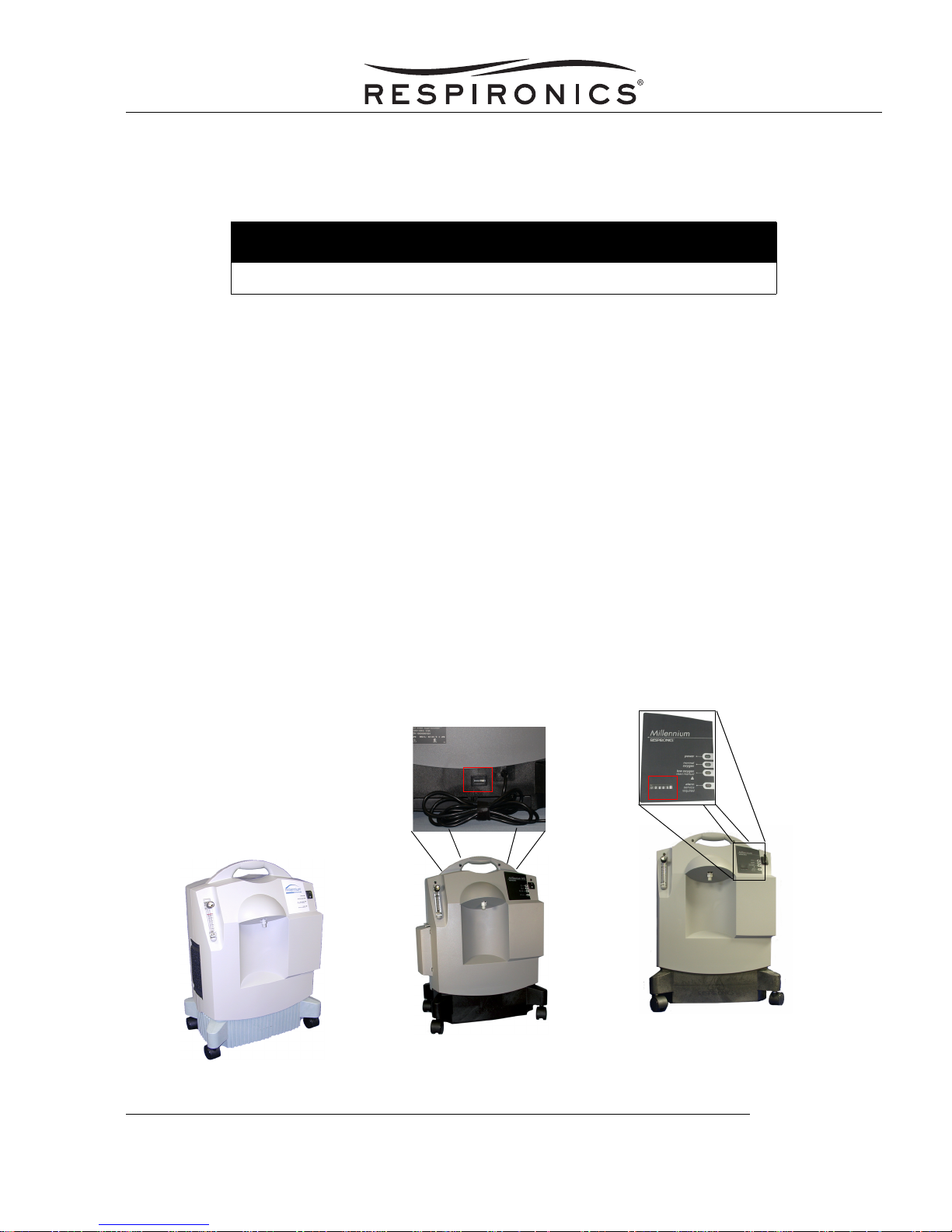
TYPES OF CONCENTRATORS
MILLENNIUM H600/H605 CONCENTRATORS
The Millennium H600/605 Concentrators are equipped with a green cabinet and a fluted Base Cabinet.
MILLENNIUM M600/M605/M10600/M10605 CONCENTRATORS
The Millennium M600/M605/M10600/M10605 Concentrators comes equipped with a grey cabinet, a black
Base Cabinet, and the Hour Meter is located in the Base Cabinet.
MILLENNIUM ENHANCED M600/M605/M10600/M10605 CONCENTRATORS
The Millennium Enhanced M600/M605/M10600/M10605 Concentrators comes equipped with a grey cabinet, a
black Base Cabinet, and the Hour Meter is located on the front panel of the Front Cabinet.
Enhanced
H600/H605 Concentrator
M600/M605
M10600/M10605
Concentrator
M600/M605
M10600/M10605
Concentrator
INTRODUCTION - PAGE 11041846, REV. 00
MILLENNIUM SERVICE & TECHNICAL INFORMATION
Page 13

SERVICE NOTICE
The Millennium is designed so that trained Service Technicians can perform repair and testing procedures. The
information provided in this manual will allow service technicians to perform the service and maintenance
required on the Millennium. The individual(s) using this manual should have prior training or experience
servicing oxygen concentrators.
SERVICE TRAINING
Respironics offers service training for the Millennium Concentrators. Training includes complete disassembly
of the device, troubleshooting subassemblies and components, and performance testing. For more
information, contact the Service Marketing department at:
E-mail: service.operations@respironics.com
Phone: (724) 755-8220
Fax: (724) 755-8230
SERVICE/TECHNICAL SUPPORT STATEMENT
For technical assistance, please contact Respironics Customer Service.
U.S.A. and Canada
Phone:1-800-345-6443
Fax: 1-800-886-0245
International
Phone: 1-724-387-4000
Fax: 1-724-387-5012
MILLENNIUM SERVICE & TECHNICAL INFORMATION
1041846, REV. 00PAGE 2 - INTRODUCTION
Page 14
WARNINGS & CAUTIONS
SECTION OVERVIEW
Warnings and Cautions, are used throughout this manual to identify possible safety hazards, conditions that
may result in equipment or property damage, and important information that must be considered when
performing service and testing procedures on the Millennium Oxygen Concentrators.
Please read this section carefully before servicing the Millennium Oxygen Concentrators.
WARNING
Warnings indicate the possibility of injury to the patient, operator, or technician.
CAUTION
Cautions indicate the possibility of damage to the device
NOTE
Notes are used to emphasize a characteristic or important consideration.
WARNINGS
WARNINGS
• Oxygen generated by this concentrator is supplemental and should not be considered life
supporting or life sustaining. In certain circumstances, oxygen therapy can be hazardous; any
user should seek medical advice prior to using this device.
• Where the prescribing physician has determined that an interruption in the supply of oxygen, for
any reason, may have serious consequences to the user, an alternate source of oxygen should
be available for immediate use.
• Keep the unit away from heat and/or open flame as oxygen greatly accelerates combustion.
• Do not smoke when the concentrator is operating or patient is using the oxygen.
• Do not use greases, oils, or any petroleum based solvent or cleaner on or near the unit.
• Use extreme caution when handling the Compressor Capacitor as it holds an electrical charge
until it is properly discharged.
• Avoid handling the molecular sieve material. Respironics recommends the return of the Sieve
Canister Assembly to Respironics for any service that involves sieve disposal.
• Never modify the Power Cord or use adapters, extension cords, etc. The unit is double insulated
and uses a 2-prong not a 3-prong Power Cord. Any modification to the Power Cord could alter
the safety feature.
WARNINGS & CAUTIONS - PAGE 11041847, REV. 00
MILLENNIUM SERVICE & TECHNICAL INFORMATION
Page 15

WARNINGS (CONT’D)
• A physician must prescribe use of a humidifier with the Millennium. Use of only bubble type
humidifiers is recommended and connections must be secure and free of leaks.
• If the Millennium Oxygen Concentrator has been subjected to hot or cold temperatures for an
extended period of time, it should be allowed to warm up to the stated operating temperatures
before power up. Failure to do so could result in improper performance and or alarm conditions
until the unit reaches normal operating temperatures.
• Do not turn on the unit while any filter is wet or moist.
CAUTIONS
CAUTIONS
• U.S. federal law restricts this device to sale by or on the order of a physician.
• Place the unit where cooling airflow is unrestricted. Be sure to inform the user not to position the
unit close to drapery or curtains that might restrict the airflow.
• When using a liquid leak detector, be careful not to allow it to contact electrical parts.
• Make sure connections of fittings, tubing, and hoses are secure.
• Be cautious when using thread sealants because they can cause extensive damage to the
internal parts of the unit if allowed within tubing or fittings.
• Device operation above or outside of the Voltage, LPM, Temperature, Humidity and /or Altitude
values specified in the manual may decrease oxygen concentration levels.
• Clean all exterior cabinet surfaces periodically by wiping with a damp cloth, using a mild detergent
and/or hospital disinfectant.
• If the 25-foot tubing, connector, and high flow cannula supplied with the Millennium M10 Oxygen
Concentrator are not used, 10 LPM of oxygen flow may not be achieved.
• Use only Respironics or factory-authorized replacement parts and accessories.
NOTES
• Make sure the Flow Meter is set at the patient’s prescribed flow rate once patient circuitry is
attached.
• Make sure there are no kinks in the user’s oxygen tubing. If necessary, use a non-kink style
delivery tube (unit will go into an audible and visual alarm if the tubing is kinked or the flowmeter is
turned completely off).
MILLENNIUM SERVICE & TECHNICAL INFORMATION
NOTES
1041847, REV. 00PAGE 2 - WARNINGS & CAUTIONS
Page 16

SPECIFICATIONS & FEATURES
SECTION OVERVIEW
This section identifies the specifications and features of the Millennium Oxygen Concentrator.
SPECIFICATIONS & FEATURES - PAGE 11041848, REV. 00
MILLENNIUM SERVICE & TECHNICAL INFORMATION
Page 17
H600/605, M600/605, & ENHANCED M600/605 SPECIFICATIONS
SPECIFICATIONS
Input Voltage 120 VAC 230 VAC 230VAC
Input Frequency 60 Hz 50 Hz 50 Hz
Average Power
Consumption
Dimensions 18.9”(L) × 13.3” (W) × 26.8” (H) (48.0 x 33.78 x 68.07 cm)
Weight 50 lbs, 22.7 kg 54 lbs, 24.7 kg
Flow Rate Variable from 0.5 to 5 lpm
Oxygen Concentration* H600/605
Enhanced M600/605
Oxygen Outlet Pressure (No
Flow)
Regulated Pressure @ 5 lpm 5.5 ± 0.25 psig
Operating Pressure 70-186 kPa
Operating Temperature 55-90° F (13-32° C)
Storage/transport
Temperature
460W 420/480W 360W
M600/605
Concentrator
92 ± 4% @ 5 lpm
94 ± 2% @ 2 lpm
H600/H605
Concentrator
>
92 @ .5 to 3 lpm
>
87 @ 4 lpm
>
89 @ 4 lpm**
>
87 @ 5 lpm**
6.0 ± 1.0 psig
-30-160° F (-34-71° C)
M600/605; Enhanced
M600/605 Concentrator
94 ± 2% @ 0.5 to 4 lpm
M605-70; Enhanced
M605-70 Concentrator
94 ± 4% @ 5 lpm
88 ± 4% @ 5 lpm
Storage/transport Humidity
Operating Humidity
Storage/Transport
Atmospheric Pressure
Altitude Up to 7,545 ft.
Sound Pressure Level (dBA) H600/605; M600/605; Enhanced M600/605 120V: 60Hz-49.8 dBA
M600/605; Enhanced M600/605 230V (except M605-70): <43dBA
M600/605; Enhanced M605-70: <40dBA
H600/605 230V <42dBA
* Oxygen concentration levels are for operation within specified temperatures and altitude ranges.
Operation outside specified ranges may decrease oxygen concentration levels.
** Specifications achieved only at the following operating parameters: 20 ° C (68 ° F), 50% relative
humidity, and 1017 mbar.
MILLENNIUM SERVICE & TECHNICAL INFORMATION
Up to 95% non-condensing
790-525 mm Hg
Up to 2300 m
1041848, REV. 00PAGE 2 - SPECIFICATIONS & FEATURES
Page 18
SAFETY
Pressure Relief Valve 40 ± 3 psig (303 ± 20.7 kPa)
Compressor Compartment Thermal
Protection with Self Reset
149° F (65° C)
ALARM CONDITIONS
Visual Red Light Emitting Diode (LED) and audible sound alert:
• Start-up test;
• Power failure;
• Main PCB failure; and
• High and low pressure
Oxygen percentage indicator (Model 605 only): O
< 70%
2
ALERT CONDITIONS
H600/605 Concentrators have a yellow visual LED with intermittent audible alarm and red LED:
• No oxygen flow
Oxygen percentage indicator (model 605): 70% < O
M600/605; Enhanced M600/605 Concentrators have a yellow LED with intermittent audible alarm and
red LED:
< 85%
2
• No oxygen flow
Oxygen percentage indicator (model 605): 70% < O
< 82%
2
POWER INDICATION
Visual, green LED (next to Power Switch).
OXYGEN PERCENTAGE INDICATOR (MODEL 605)
H605 Concentrators
Warnings Conditions: Blinking yellow LED after unit is turned on and until O
Normal Oxygen: Visual green LED when O
M605; Enhanced M605 Concentrators
Warnings Conditions: Blinking yellow LED after unit is turned on and until O
Normal Oxygen: Visual green LED when O
MILLENNIUM SERVICE & TECHNICAL INFORMATION
> 85%.
2
> 82%.
2
SPECIFICATIONS & FEATURES - PAGE 31041848, REV. 00
> 85%.
2
> 82%.
2
Page 19

M10600/M10605 & ENHANCED M10600/M10605 SPECIFICATIONS
SPECIFICATIONS
Input Voltage 120 VAC
Input Frequency 60 Hz
Average Power Consumption 600W
Dimensions 19”(L) × 13” (W) × 27” (H) (48.0 x 33.0 x 69.0 cm)
Weight 53 ± 0.5 lbs, (24 ± 0.23 kg)
Flow Rate Variable from 1 to 10 lpm
Oxygen Concentration* 92 ± 4% @ 8 - 10 lpm
94 ± 2% @ 3 - 7 lpm
92 ± 4% @ 1 - 2 lpm
Oxygen Outlet Pressure (No Flow) 6.0 ± 1.0 psig
Regulated Pressure @ 10 lpm 5.5 ± 0.25 psig
Operating Pressure 10 - 30 psig
Operating Temperature 55-90° F (15-32° C)
Storage/transport Temperature -30-160° F (-34-71° C)
Storage/Transport/Operating
Humidity
Storage/Transport Atmospheric
Pressure
Altitude Up to 1,368 ft.
Sound Pressure Level (dBA) <50 dBA
* Oxygen concentration levels are for operation within specified voltages, lpm,
temperatures and altitude ranges. Operation outside specified ranges may decrease
oxygen concentration levels.
Up to 95% non-condensing
790-525 mm Hg
Up to 417 m
Verify flow and purity at higher altitudes.
MILLENNIUM SERVICE & TECHNICAL INFORMATION
1041848, REV. 00PAGE 4 - SPECIFICATIONS & FEATURES
Page 20
SAFETY
Compressor Compartment Thermal
Protection with Self Reset
149° F (65° C)
ALARM CONDITIONS
Visual Red LED and audible sound alert:
• Start-up test;
• Power failure;
• Main PCB failure; and
• High and low pressure
Oxygen percentage indicator (M10605): O
<70%)
2
ALERT CONDITIONS
Concentrators have a have a yellow visual LED with intermittent audible alarm and red LED:
• No oxygen flow
Oxygen percentage indicator (M10605): 70% <O
< 82%
2
POWER INDICATION
Visual, green LED (below to Power Switch).
OXYGEN PERCENTAGE INDICATOR (MODEL 605)
Warnings Conditions: Blinking yellow LED after unit is turned on and until O2 > 82%.
Normal Oxygen: Visual green LED when O
> 82%.
2
SPECIFICATIONS & FEATURES - PAGE 51041848, REV. 00
MILLENNIUM SERVICE & TECHNICAL INFORMATION
Page 21

FRONT CABINET FEATURES
FLOW METER
Used to set and indicate amount of oxygen flowing from unit to patient. Adjustable from 0.5 to 5 or 10 lpm,
depending on the concentrator.
DISS OUTLET FITTING
A male DISS fitting used to connect the mating connector from the humidifier bottle or the patient’s cannula.
POWER SWITCH
Used to turn the device On and Off.
CONTROL OVERLAY
Indicates the red alarm light, the green ON light, and the Oxygen percentage (Model 605 and M10605 Only).
HOUR METER (ENHANCED M600/605; ENHANCED M10600/M10605 MODEL ONLY)
Indicates cumulative hours of unit operation.
REAR AND SIDE CABINET FEATURES
SERIAL PLATE
Lists model and serial numbers, requirements, and specifications.
HOUR METER (H600/605; M600/605; M10600/M10605)
Indicates cumulative hours of unit operation.
PRE-INLET FILTER
Filters the air that enters the concentrator.
REAR ACCESS DOOR
Allows access to the following:
• Inlet pre-filter, inlet filter configuration, Silencer, or
• Long Life Filter Configuration (Enhanced M10600/M10605), and
• Battery
POWER CORD
Used to connect concentrator to AC power receptacle.
MILLENNIUM SERVICE & TECHNICAL INFORMATION
1041848, REV. 00PAGE 6 - SPECIFICATIONS & FEATURES
Page 22
CONTROL PANEL FEATURES
CONDITIONS CAUSE
AC Power Solid Green LED
Normal Oxygen Condition OPI units only (Model 605); solid green LED with no
alarm sound
Low Oxygen Alert Condition with Red LED Solid yellow LED with intermittent (every 2 seconds)
audible alarm
Alarm Condition Solid red LED and continuous audible
Start-up Test Light all LED’s and sound audible alarm for 2 seconds
after power on
Warm-up Condition OPI units only (Model 605); blinking yellow LED with no
alarm sound.
SPECIFICATIONS & FEATURES - PAGE 71041848, REV. 00
MILLENNIUM SERVICE & TECHNICAL INFORMATION
Page 23

This page intentionally left blank.
MILLENNIUM SERVICE & TECHNICAL INFORMATION
1041848, REV. 00PAGE 8 - SPECIFICATIONS & FEATURES
Page 24

SYSTEM SETUP
SECTION OVERVIEW
This section describes the procedures that should be performed prior to patient use and periodically to ensure
proper setup and operation.
SYSTEM SETUP
1. Remove the rear access door and verify that the proper filters are in place.
2. Ensure that filters are secure. Twist the filter while firmly pressing downwards.
3. Before connecting the unit to a power source, perform the following procedure to check battery
condition and alarm function.
a. Move the Power Switch to the ON (I) position. The alarm should sound and the red LED
should illuminate.
b. Move the Power Switch to the OFF (0) position. The alarm and the red LED light should go
off.
4. Connect the Power Cord to a power source.
5. Turn on the unit by moving the Power Switch to the ON (I) position and verify the following:
• all LED’s illuminate and audible alarm sounds for two seconds;
• the unit starts running; and
• the green power LED remains illuminated.
NOTE
If you have a Model 605, which is equipped with the oxygen percentage indicator (OPI), the yellow
LED light will blink until the oxygen purity is above 85% for H600/605 Concentrators and above
82% for M600/605; Enhanced M600/605 Concentrators. The green normal oxygen LED
illuminates, once appropriate O
6. Adjust the Flow Meter to max. 5 or 10 lpm depending on the concentrator. Turning the Flow Meter
clockwise decreases the flow, and turning it counter-clockwise increases the flow.
7. If the items above are working properly, proceed to step 8. If there is a problem refer to the Troubleshooting section.
8. Attach a calibrated Oxygen Analyzer to the DISS outlet fitting. The oxygen concentration should
be as specified in the Specifications section.
purity is achieved.
2
SYSTEM SETUP - PAGE 11041812, REV. 00
MILLENNIUM SERVICE & TECHNICAL INFORMATION
Page 25

This page intentionally blank.
MILLENNIUM SERVICE & TECHNICAL INFORMATION
1041812, REV. 00PAGE 2 - SYSTEM SETUP
Page 26
THEORY OF OPERATION
SECTION OVERVIEW
This section describes the theory of operation for the Millennium Oxygen Concentrators.
H600/605; M600/605; ENHANCED M600/605 CONCENTRATOR PNEUMATIC
PERATION
O
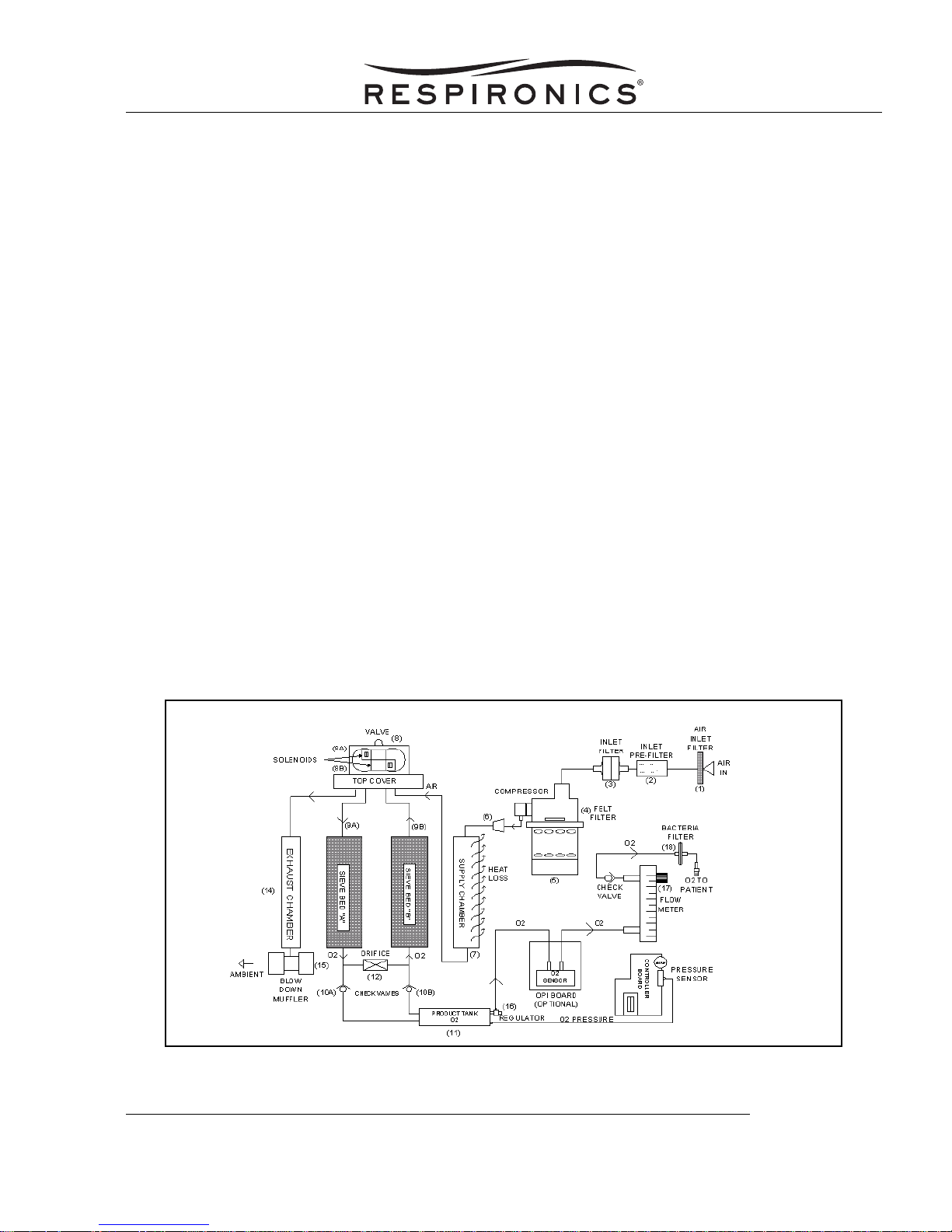
Room air enters through a foam air inlet filter (1) mounted on the side of the cabinet. The primary system air is
drawn through the inlet pre-filter, (2) the inlet filter (3) and then through the felt filter (4) by the Compressor (5).
The exhaust air then passes through the In-line Muffler (6) to the supply chamber.
The Compressor exhaust air is cooled by the supply chamber (7) and distributed using a pneumatic Valve/
Solenoid Assembly (8). At start up, valve (8) is de-energized allowing compressed air to flow into both Sieve
Canisters (9) until the pressure sensor builds up to switching pressure. At switching pressure, a 12 volt signal
is received at Valve/Solenoid(8a) closing the input and allowing compressed air to continue through sieve bed
(9a) for 6.25 seconds absorbing the Nitrogen and allowing the Oxygen to flow through check valve (10a) and
into the product tank (11).
At 5 liters of flow approximately 1/3 of the Oxygen is deposited into the product tank and 2/3 is passed through
orifice (12) in to sieve bed (9b) to purge the Nitrogen from the sieve bed, which exits through the exhaust port
of the Valve/Solenoid(8b) to exhaust chamber (14) through Blow Down Muffler (15) to outside air in a time of
6.25 seconds.
At the end of this cycle the unit will balance for 1 second which de-energizes valve / solenoid (8b) and allows
compressed air to flow into both Sieve Canisters. The pressure reaches the max switching pressure and sends
a 12 volt signal to valve / solenoid (8b) and the adsorption cycle starts over in the Sieve Canister (9b). Oxygen
is in a continuous flow from the product can (11) through the regulator (16) through the Flow Meter (17) to the
bacteria filter (18) to the patient.
F
IGURE A: H600/605; M600/605; ENHANCED M600/605 PNEUMATIC BLOCK DESIGN
THEORY OF OPERATION - PAGE 11041905, REV. 00
MILLENNIUM SERVICE & TECHNICAL INFORMATION
Page 27
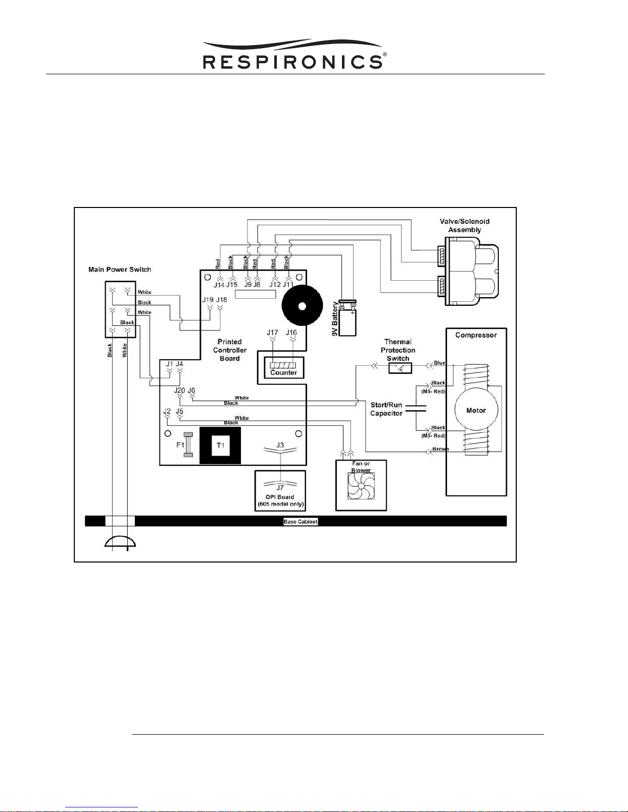
H600/605; M600/605; ENHANCED M600/605 CONCENTRATOR ELECTRICAL
PERATION
O
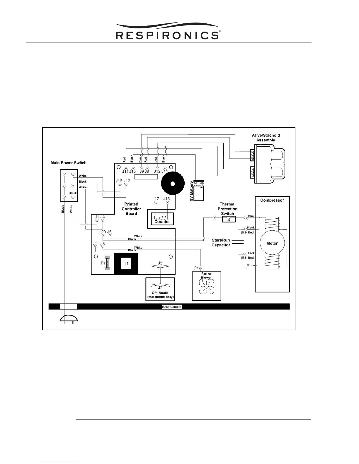
Power is supplied from the two-prong plug to the Power Switch. When the Power Switch is ON, 120 VAC/230
VAC power is supplied to the Compressor motor, Hour Meter, cooling fan, and the main circuit board.
The main circuit board consists of a linear power supply, pressure sensor, software driven microprocessor,
green, yellow, and red LED’s and audible alarm.
The 9-volt battery provides a power source to operate the audible alarm and the red LED alarm light in the
event of an AC power failure.
F
IGURE B: H600/605; M600/605; ENHANCED M600/605 ELECTRONIC COMPONENT BLOCK DIAGRAM
MILLENNIUM SERVICE & TECHNICAL INFORMATION
1041905, REV. 00PAGE 2 - THEORY OF OPERATION
Page 28

M10600/M10605; ENHANCED M10600/M10605 CONCENTRATOR PNEUMATIC
PERATION
O
Room air is drawn through a foam air inlet filter (1) mounted on the side of the cabinet. The primary system air
is drawn through the inlet pre-filter, (2) the inlet filter w/ silencer (3) by the Compressor (5). The exhaust air
then passes through the In-line Muffler (6) to the supply chamber.
The Compressor exhaust air is cooled by the supply chamber (7) and distributed using a pneumatic Valve/
Solenoid Assembly (8). At start up, valve (8) is de-energized allowing compressed air to flow into both Sieve
Canisters (9) until the pressure sensor builds up to switching pressure. At switching pressure, a 12 volt signal
is received at Valve/Solenoid(8a) closing the input and allowing compressed air to continue through sieve bed
(9a) for 6.25 seconds absorbing the Nitrogen and allowing the Oxygen to flow through check valve (10a) and
into the product tank (11).
At 5 liters of flow approximately 1/3 of the Oxygen is deposited into the product tank and 2/3 is passed through
orifice (12) in to sieve bed (9b) to purge the Nitrogen from the sieve bed, which exits through the exhaust port
of the Valve/Solenoid(8b) to exhaust chamber (14) through Blow Down Muffler (15) to outside air in a time of
6.25 seconds.
At the end of this cycle the unit will balance for 1 second which de-energizes valve / solenoid (8b) and allows
compressed air to flow into both Sieve Canisters. The pressure reaches the max switching pressure and sends
a 12 volt signal to valve / solenoid (8b) and the adsorption cycle starts over in the Sieve Canister (9b). Oxygen
is in a continuous flow from the product can (11) through the regulator (16) through the Flow Meter (17) to the
bacteria filter (18) to the patient.
F
IGURE C: M10600/M10605; ENHANCED M10600/M10605 PNEUMATIC BLOCK DESIGN
THEORY OF OPERATION - PAGE 31041905, REV. 00
MILLENNIUM SERVICE & TECHNICAL INFORMATION
Page 29
M10600/M10605; ENHANCED M10600/M10605 ELECTRICAL OPERATION
Power is supplied from the two-prong plug to the Power Switch. When the Power Switch is ON, 120 VAC
power is supplied to the Compressor motor, Hour Meter, cooling fan, and the main circuit board.
The main circuit board consists of a linear power supply, pressure sensor, software driven microprocessor,
green, yellow, and red LED’s and audible alarm.
The 9-volt battery provides a power source to operate the audible alarm and the red LED alarm light in the
event of an AC power failure.
F
IGURE D: M10600/M10605; ENHANCED M10600/M10605 ELECTRONIC COMPONENT BLOCK DIAGRAM
MILLENNIUM SERVICE & TECHNICAL INFORMATION
1041905, REV. 00PAGE 4 - THEORY OF OPERATION
Page 30

MAINTENANCE
This section describes the scheduled and routine maintenance procedures. The maintenance procedures
must be performed on the Millennium Oxygen Concentrator System as part of the normal care of the unit.
Maintenance is very important in prolonging dependability and in reducing costly repairs. Long-term
maintenance and regular checking of the filters helps assure the efficient operation of the unit. The user
should be instructed on how to clean the accessible filters. An authorized technician should perform all other
maintenance.
MAINTENANCE INTERVALS
WEEKLY USER MAINTENANCE
Weekly user maintenance consists of inspecting and cleaning the Inlet Filter.
DEALER ANNUAL MAINTENANCE
Annual maintenance shall be performed by the Home Care Dealer, or at a Respironics service facility. Annual
maintenance includes the following.
• Checking the condition of the Filters (change if necessary).
• Cleaning the cabinet.
• Verifying the oxygen concentration with a calibrated oxygen analyzer. This procedure must be
performed once a year or between patients. Refer to the Testing Section for more detail.
• Perform a power interrupt alarm test, and replace the 9-volt battery if necessary. Refer to the Test-
ing Section for more detail.
• Perform a start-up LED and audible alarm test. Refer to the Testing Section for more detail.
NOTE
For units equipped with the Long Life Filter, Respironics recommends
checking and replacing the Long Life Filter every two (2) years. For all other
Maintenance follow the Dealer Annual Maintenance Guidelines listed above.
MAINTENANCE - PAGE 11041813, REV. 00
MILLENNIUM SERVICE & TECHNICAL INFORMATION
Page 31

DEALER PERIODIC MAINTENANCE
Periodic maintenance shall be performed by the Home Care Dealer, or at a Respironics service facility.
Periodic maintenance includes the following:
• Checking the final patient bacteria filter and replacing if necessary.
• Measuring the product canister pressure.
NOTE
If the product canister pressure is lower than normal, but the unit has clean
filters and no leaks, then Compressor maintenance should be performed.
DEALER COMPRESSOR MAINTENANCE
NOTE
The Compressor can be returned to the Compressor manufacturer to be recertified.
Compressor maintenance shall be performed by the Home Care Dealer, or at a Respironics service facility.
Compressor maintenance is required by Respironics to prolong dependability of the concentrator. However,
the need for this maintenance varies depending on the operating conditions and the environment where the
unit is used. Some signs of poor Compressor performance are:
• low oxygen readings,
• low pressure readings, and
• increased noise level.
Compressor maintenance shall be performed at intervals commensurate with hospital or home care provider
guidelines. Compressor Maintenance includes the following:
A. C
LEANING THE AIR INLET FILTER
1. Remove the Air Inlet Filter from the side of the unit.
2. Vacuum or wash the Air Inlet Filter with a mild detergent and tap water.
3. If washed, allow the Air Inlet filter to air dry completely before installing it on the unit.
F
IGURE A: LOCATION OF THE AIR INLET FILTER
MILLENNIUM SERVICE & TECHNICAL INFORMATION
1041813, REV. 00PAGE 2 - MAINTENANCE
Page 32

B. CLEANING THE PRE-INLET FILTER & INLET FILTER
1. Remove the rear access door from the unit.
IGURE B: REMOVING THE REAR ACCESS DOOR
F
2. Remove the Pre-inlet Filter and the Inlet Filter from the unit.
3. Remove the Pre-inlet Filter from the Inlet filter.
4. Wash the foam Pre-inlet Filter with a mild detergent and tap water. Allow it to air dry completely.
5. Inspect the Inlet filter and replace if necessary.
6. Place the assembled filters on the filter cover. While firmly pressing down on the filter assembly,
turn the filter assembly clock-wise to assure of a tight fit between the filter assembly and the filter
cover.
7. Install the rear access door.
F
IGURE C: FILTER LOCATIONS
MILLENNIUM SERVICE & TECHNICAL INFORMATION
MAINTENANCE - PAGE 31041813, REV. 00
Page 33

C. CLEANING THE CABINET
1. Disconnect the unit from the power source.
2. Using a mild detergent and disinfectant, clean all exterior surfaces of the cabinet.
CAUTION
Do not allow any liquid to enter the unit.
3. Ensure that the cabinet is dry before placing in service.
D. M
ICRO-DISK FILTER MAINTENANCE
The Micro-disk filter is the final component in the filtering system before the concentrated oxygen is delivered
to the patient. Check and replace this filter as necessary.
PART NUMBER: H621
Included in Kit Tools Required
Procedure
1. Remove the Rear Cabinet.
Micro-disk Filter (x6)
Wire Ties (x2)
Phillips Screwdriver
(No. 2 Medium w/ long shaft)
Diagonals (wire cutters)
WARNING
Electrical shock hazard; Disconnect the electrical supply before attempting to make
any repairs.
CAUTION
Electronic components used in this device are subject to damage from static
electricity. Repairs made to this device must be performed only in an antistatic,
ESD protected environment.
MILLENNIUM SERVICE & TECHNICAL INFORMATION
1041813, REV. 00PAGE 4 - MAINTENANCE
Page 34

2. Remove the Front Cabinet, and separate it from the unit.
IGURE D: MICRO-DISK FILTER LOCATION
F
3. Using the diagonals, cut the wire ties that secure the pressure tubing to the Micro-disk filter.
4. Remove the pressure tubing from the inlet and outlet ports of the Micro-disk filter.
5. Slide the pressure tubing onto the inlet and outlet ports of the new Micro-disk filter.
6. Using the wire ties provided, secure the pressure tubing to the new Micro-disk filter.
7. Use the diagonals to cut off the excess from the wire ties.
MAINTENANCE - PAGE 51041813, REV. 00
MILLENNIUM SERVICE & TECHNICAL INFORMATION
Page 35

E. H00/605 (120V/230V); M600/605 (120V); ENHANCED M600/605 (120V) COMPRESSOR MAINTENANCE
PART NUMBER: H610
Included in Kit Tools Required
• Piston Cup
• Piston cup retainer
• Valve keeper / restraint (exhaust)
• Valve keeper (intake)
• Cylinder Sleeve
• Valve flapper (exhaust)
• Valve flapper (intake)
• O-ring (sleeve)
• O-ring (intake filter cover)
• Gasket (valve plate)
• Cork gasket
• Filter (felt)
• Screw (valve keeper x2)
• Screw (piston cup retainer x4)
• In-line Muffler (molded fittings)
• Clamp (one ear x3)
• Hose (3/8 ID Braided)
• Millennium Screwdriver (RI p/n H646)
• Flat blade screwdriver (medium)
• T-15, T-20, T-25 Torx bits (Included with
Millennium screwdriver)
• Torque wrench, 30 in.-lbs (RI p/n 1033057)
• One Ear Clamp Pliers (RI p/n H645)
NOTE
Respironics requires that all components of the Compressor maintenance kit be used to ensure
that the Compressor will function properly after Compressor maintenance has been performed.
WARNING
Electrical shock hazard; Disconnect the electrical supply
before attempting to make any repairs to the device.
CAUTION
Electronic components used in this device are subject to damage from
static electricity. Repairs made to this device must be performed only
in an antistatic, ESD-protected environment.
1041813, REV. 00PAGE 6 - MAINTENANCE
MILLENNIUM SERVICE & TECHNICAL INFORMATION
Page 36

Procedure
1. Remove the Rear Cabinet. Refer to the proper Repair & Replacement section for detailed instruc-
2. Remove the Front Cabinet. Refer to the proper Repair & Replacement section for detailed instruc-
3. Remove the Compressor Cover/ Perforated Canopy. Refer to the proper Repair & Replacement
4. Remove the four screws securing the filter cover using a T-20 or 7/64 Torx bit.
tions.
tions.
section for detailed instructions.
F
IGURE E: SCREW LOCATION
5. Remove and replace the felt filter inside the filter cover.
IGURE F: FELT FILTER
F
MAINTENANCE - PAGE 71041813, REV. 00
MILLENNIUM SERVICE & TECHNICAL INFORMATION
Page 37

6. Remove and replace the O-ring on the bottom side of the filter body.
F
IGURE G: O-RING LOCATION
7. Remove the four screws securing the Compressor head using a T-25 or 1/8 Torx bit.
IGURE H: COMPRESSOR HEAD SCREW LOCATIONS
F
MILLENNIUM SERVICE & TECHNICAL INFORMATION
1041813, REV. 00PAGE 8 - MAINTENANCE
Page 38

8. Remove the valve plate and cylinder sleeve.
IGURE I: REMOVING THE VALVE PLATE AND CYLINDER SLEEVE
F
9. Separate the cylinder sleeve from the valve plate, and discard the sleeve and O-ring.
IGURE J: SEPARATING THE CYLINDER SLEEVE AND VALVE PLATE
F
MAINTENANCE - PAGE 91041813, REV. 00
MILLENNIUM SERVICE & TECHNICAL INFORMATION
Page 39

10. Remove the screws, and replace the valve flappers on the valve plate using a 1/4 in. nut driver.
Valve Keeper
Strips
Valve Gasket
IGURE K: FLAPPER VALVE REMOVAL
F
NOTE
The Valve flappers are located under the keeper strips.
11. Remove and replace the gasket on the valve plate.
12. Using a T-20 torx bit, remove and discard the four screws, the piston cup, the retainer plate and
the cork gasket from the connecting rod assembly.
NOTE
A heat gun may be used to loosen the loctite on the screws.
MILLENNIUM SERVICE & TECHNICAL INFORMATION
1041813, REV. 00PAGE 10 - MAINTENANCE
Page 40

FIGURE L: LOCATION OF THE PISTON CUP RETAINER SCREWS
13. Place the new cork gasket on the connecting rod assembly, making sure the cork fits around the
pins on the connecting rod assembly.
IGURE M: INSTALLING THE CORK GASKET
F
MILLENNIUM SERVICE & TECHNICAL INFORMATION
MAINTENANCE - PAGE 111041813, REV. 00
Page 41

14. Place the new piston cup on the back of the new retainer plate. Using the new screws provided,
secure the retainer to the connecting rod assembly and torque screws to 30 in.-lbs.
F
IGURE N: INSTALLING THE PISTON CUP & RETAINER
15. Set the new sleeve in place with the O-ring away from the piston. Slide the sleeve down over the
piston cup using your fingers to guide the sleeve without damaging the piston cup.
F
IGURE O: INSTALLING THE CYLINDER SLEEVE
MILLENNIUM SERVICE & TECHNICAL INFORMATION
1041813, REV. 00PAGE 12 - MAINTENANCE
Page 42

FIGURE P: CYLINDER SLEEVE IN PLACE
16. Press the valve plate onto the cylinder sleeve making sure not to pinch the O-ring on the cylinder
sleeve. The valve plate must be positioned properly to ensure proper alignment with the Compressor head. Place the valve gasket in the groove of the valve plate.
Alignment
Holes
Valve Gasket
F
IGURE Q: VALVE GASKET & ALIGNMENT HOLES
MILLENNIUM SERVICE & TECHNICAL INFORMATION
MAINTENANCE - PAGE 131041813, REV. 00
Page 43

17. Place the Compressor head onto the valve plate. Using a T-25 Torx bit and a torque wrench,
tighten the Compressor head bolts to 30 in.-lbs.
IGURE R: COMPRESSOR HEAD IN PLACE
F
18. Place the new Felt filter and the O-ring on the Intake filter body.
19. Connect the In-line Muffler to the bottom of the Compressor head and secure with a clamp.
MILLENNIUM SERVICE & TECHNICAL INFORMATION
1041813, REV. 00PAGE 14 - MAINTENANCE
Page 44

M600/605 (230V); ENHANCED M600/605 (230V); M10600/M10605; ENHANCED M10600/M10605 COMPRESSOR
M
AINTENANCE
PART NUMBER: 1018249
Included in Kit Tools Required Applicable Concentrator
• Piston Cup (x2)
• Cylinder Sleeve (x2)
• Cylinder O-ring (x2)
• Head Screws (x8)
• Head Gasket (x2)
• Cup Retainer Screws
(x2)
• Valve Restraint (x2)
• Valve Keeper (x4)
• Valve (x4)
• Valve Screw (x4)
• Dynamic Backer (x2)
• Millennium Screwdriver (w/bits) (RI p/n
H646)
• Cutting Pliers
• Heat Gun (acceptable ranges, 200°F
thru 900°F)
• 3/8” Drive Hex Bit Holder (RI p/n
1040446)
• 1/4” Drive Hex bit holder (RI p/n
1033058)
• Torque Wrench, 18in-lbs (RI p/n
1018495)
• Torque Wrench, 55 in-lbs (RI p/n
1018490)
• Torque Wrench, 100 in-lbs (RI p/n
1024064)
• Torque Wrench, 125 in-lbs (RI p/n
1024062)
• 1/8” Allen wrench or Hex bit
• 5/32” Allen Wrench or Hex bit
• T-25 and T-27 Torx bit
• M10600/M10605
• Enhanced M10600/
M10605
• Vice
• Socket wrench
• Soft cloth
• One Ear Clamp Pliers (RI p/n H645)
MILLENNIUM SERVICE & TECHNICAL INFORMATION
MAINTENANCE - PAGE 151041813, REV. 00
Page 45

PART NUMBER: 1015569
Included in Kit Tools Required Applicable
Concentrator
• Piston Cup (x2)
• Cylinder Sleeve (x2)
• Cylinder O-ring (x2)
• Head Screws (x8)
• Head Gasket (x2)
• Cup Retainer Screws
(x2)
• Valve Restraint (x2)
• Valve Keeper (x4)
• Valve (x4)
• Valve Screw (x4)
• Instruction Sheet
• Dynamic Backer (x2)
• Millennium Screwdriver (w/bits) (RI p/n
H646)
• Cutting Pliers
• Heat Gun (acceptable ranges, 200°F thru
900°F)
• 3/8” Drive Hex Bit Holder (RI p/n 1040446)
• 1/4” Drive Hex bit holder (RI p/n 1033058)
• Torque Wrench, 18in-lbs (RI p/n 1018495)
• Torque Wrench, 55 in-lbs (RI p/n 1018490)
• Torque Wrench, 100 in-lbs (RI p/n
1024064)
• Torque Wrench, 125 in-lbs (RI p/n
1024062)
• 1/8” Allen wrench or Hex bit
• 5/32” Allen Wrench or Hex bit
• T-25 and T-27 Torx bit
• Vice
• Socket wrench
• Soft cloth
• One Ear Clamp Pliers (RI p/n H645)
• M600/605 230V
• Enhanced
M600/M605
230V
Respironics requires that all components of the Compressor maintenance kit be used to ensure
that the Compressor will function properly after Compressor maintenance has been performed. It
is also recommended that the In-line Muffler be replaced (RI p/n 1018460)
Electrical shock hazard; Disconnect the electrical supply before
attempting to make any repairs to the device.
Electronic components used in this device are subject to damage from static electricity. Repairs
made to this device must be performed only in an antistatic, ESD-protected environment.
MILLENNIUM SERVICE & TECHNICAL INFORMATION
NOTE
WARNING
CAUTION
1041813, REV. 00PAGE 16 - MAINTENANCE
Page 46

Procedure
1. Remove the Rear Cabinet. Refer to the proper Repair & Replacement section for detailed instruc-
2. Remove the Front Cabinet. Refer to the proper Repair & Replacement section for detailed instruc-
3. Remove the Compressor Cover/ Perforated Canopy. Refer to the proper Repair & Replacement
4. Disconnect the exhaust tubing, Capacitor wires and input power wiring from the Compressor
5. Using a 1/8” Allen wrench or 1/8” Hex bit, remove the four Compressor mounts.
tions.
tions.
section for detailed instructions.
assembly.
F
IGURE S: COMPRESSOR MOUNTS (2 OF 4 SHOWN)
6. Lift the Compressor assembly out of the Millennium Base.
7. Before disassembly, mark the outside corners on one side of the Compressor to ensure proper
valve plate and Compressor head orientation during reassembly.
F
IGURE T: CORNER MARKINGS
MAINTENANCE - PAGE 171041813, REV. 00
MILLENNIUM SERVICE & TECHNICAL INFORMATION
Page 47

8. Remove the eight screws securing the Compressor head cover using a T-25 Torx bit or flathead
screwdriver. Remove the Compressor head cover.
IGURE U: SCREW LOCATIONS
F
9. Remove both valve plates from the Compressor.
10. Remove the flapper screw from the Compressor head side of the valve plate. Take note of the cutouts on the flapper. The new flapper must be placed in the same fashion during assembly. Discard the old flapper, keeper, restraint, and gasket.
11. Clean the plate with a soft cloth. Install the new flapper. Place the new restraint on top of the flapper. The keeper should be placed on top of the restraint so the word “UP” is visible. Tighten the
flapper screw to 18 in-lbs. Install the new gasket.
12. Perform this procedure on the second valve plate.
MILLENNIUM SERVICE & TECHNICAL INFORMATION
IGURE V: VALVE PLATE
F
1041813, REV. 00PAGE 18 - MAINTENANCE
Page 48

13. Turn the valve plate over to the cylinder side.
IGURE W: CYLINDER SIDE OF VALVE PLATE
F
14. Remove the flapper screw. Once again, ensure to note the flapper cutouts before disassembly.
Discard the flapper keeper and O-ring.
15. Clean the plate with a clean cloth.
16. Install the new flapper. Place the keeper on top of the flapper so that the word “UP” is visible.
Tighten the screw to 18 in-lbs. Install the new O-ring.
17. Perform this procedure on the second valve plate and set aside the valve plates.
18. Remove and discard both cylinder sleeves.
F
IGURE X: REMOVING THE CYLINDER SLEEVE
MILLENNIUM SERVICE & TECHNICAL INFORMATION
MAINTENANCE - PAGE 191041813, REV. 00
Page 49

19. Use Figure Y as a reference to ensure proper fan orientation.
20. Pull upwards from the center of the fan. It may be necessary to rock the fan back and forth while
pulling upwards to remove it from the shaft.
Do not attempt to pull up on the outside edges of the fan blades.
MILLENNIUM SERVICE & TECHNICAL INFORMATION
IGURE Y: PROPER FAN ORIENTATION
F
CAUTION
1041813, REV. 00PAGE 20 - MAINTENANCE
Page 50

21. To remove the connecting rod assembly from the shaft, rotate the eccentric until the set screw
lines up with the Compressor housing access hole. Insert the 5/32” Allen wrench or hex bit
through the access hole and loosen the set screw 1/4 turn. Rotate the eccentric to top dead center
(180°), and slide the connecting rod/eccentric assembly off of the shaft.
F
IGURE Z: REMOVING THE ECCENTRIC
22. Wrap the neck of the connecting rod assembly with a cloth, and secure the assembly in a vice
being cautious not to clamp down on the eccentric and or bearings.
IGURE AA: CONNECTING ROD ASSEMBLY IN VICE
F
MAINTENANCE - PAGE 211041813, REV. 00
MILLENNIUM SERVICE & TECHNICAL INFORMATION
Page 51

NOTE
Considerable care must be taken while removing the piston cup retainer screw. The screw has been
tightened to 100 in-lbs with Loctite® on the threads and may become stripped if not removed properly.
23. Heat the screw with a heat gun for approximately one minute.
During this procedure, parts will become hot. Do not touch any parts with
your bare hands. Use pliers to handle the parts until they have cooled.
MILLENNIUM SERVICE & TECHNICAL INFORMATION
IGURE AB: HEATING THE SCREW
F
CAUTION
1041813, REV. 00PAGE 22 - MAINTENANCE
Page 52

24. Connect the T-27 Trox bit to the socket wrench. Press down on the wrench and turn counter
clockwise to loosen the screw. If the screw does not start to turn or the bit begins to slip, reapply
heat for one minute. Continue this process until the screw is removed. Once the parts have
cooled, discard the piston cup and screw.
F
IGURE AC: SCREW REMOVAL
25. Place a new cylinder sleeve over the piston head. Place a new piston cup on the back of the cup
retainer plate. Note the locations of the alignment pin on the back of the plate and the alignment
hole on the piston head.
26. Press the plate into the cylinder sleeve being careful not to crimp the piston cup. Once the plate is
seated on top of the piston, rotate the plate until the plate pin seats into the piston alignment hole.
Tighten the new T-27 plate screw to 100 in-lbs. Remove the rod assembly from the vice.
27. With the eccentric side of the connecting rod/eccentric assembly facing away from the Compressor, slide the assembly onto the shaft until the assembly is flush against the motor assembly.
F
IGURE AD: REPLACE PISTON CUP
MILLENNIUM SERVICE & TECHNICAL INFORMATION
MAINTENANCE - PAGE 231041813, REV. 00
Page 53

Rotate the eccentric until the set screw lines up with the housing access hole. Rotate the shaft
until the flat side of the shaft aligns with the set screw, and tighten the screw to 125 in-lbs.
28. Slide the fan onto the shaft until the fan is flush against the eccentric. Note the reference mark you
made on the fan blade in step 19 of this procedure.
29. Turn over the Compressor for access to the second connecting rod/eccentric assembly. Repeat
Steps 19 through Step 28.
30. Place the valve plates on the cylinders (O-ring side face down). The marks that were made before
disassembly must be aligned. Check the valve gaskets for proper alignment.
31. Place the Compressor head on top of the plates so that the marks align in the corners. Install the
head screws and tighten the screws to 55 in-lbs.
NOTE
If replacing the In-line Muffler, perform muffler replacement before installing the Compressor.
32. Place the Compressor on the mounts in the Base Cabinet. Make sure the springs are seated
properly.
33. Align the holes of the Compressor assembly with the standoffs in the Base Cabinet. Ensure
proper orientation of the Compressor assembly. Tighten the mounts to the base.
34. Reconnect the tubing to the Compressor exhaust port.
35. Reconnect the Compressor wires to the Capacitor and input power wiring. Proceed with final testing.
MILLENNIUM SERVICE & TECHNICAL INFORMATION
1041813, REV. 00PAGE 24 - MAINTENANCE
Page 54

MILLENNIUM OXYGEN CONCENTRATOR MAINTENANCE RECORD
Model Number: __________ Serial Number: __________ Date Purchased: __________
FILTERS COMPRESSOR
DATE HOURS LPM
Record at each check Clean and replace as needed Check and perform maintenance
9V BATTERY
Check and replace
as needed
Air Inlet1Pre-Inlet
2
OXYGEN
CONCENTRATION
Check Level Check lights
2
Inlet
2
2
Micro-disk Compressor
OPI
at start up
MOTOR START/
RUN CAPACITOR
Check and replace as
Rebuild
as recommended
recommended
In-line
Muffler
1
Patients should be instructed to position the unit so that proper
ventilation for the unit is maintained, and to clean the air inlet filter weekly.
2
Respironics requires that routine maintenance be performed annually.
NOTE
MAINTENANCE - PAGE 251041813, REV. 00
MILLENNIUM SERVICE & TECHNICAL INFORMATION
Page 55

This page intentionally left blank.
MILLENNIUM SERVICE & TECHNICAL INFORMATION
1041813, REV. 00PAGE 26 - MAINTENANCE
Page 56

TROUBLESHOOTING
SECTION OVERVIEW
This section is intended to help the service technician determine what is wrong with the Millennium Oxygen
Concentrator System. This section should also be used to determine what parts, if any, need to be replaced.
SYMPTOM CAUSE VERIFICATION CORRECTIVE ACTION
• Pressure relief
valve activating
• Low pressure alarm
• Audible and visual
alarm
• Pressure relief
valve activating
• Fluctuations in
oxygen pressure
• Fluctuations in flow
ball
Unit will not turn on
• Audible alert
(steady)
• Red LED on
(steady)
Canister to Compressor
tubing failure
• Tubing disconnected,
kinked, or hole in
tubing
• Verify the tubing
between the
canister and
Compressor is
connected
• Verify the tubing is
not kinked or
pinched
• Verify there are no
holes in the tubing
Fuse Fails
• Open fuse on Main
PCB
Pressure regulator
failure
Component failure
• Verify the audible
and visual alarm
due to battery
• Verify the flow
from regulator is
correct
• Preform Oxygen
Outlet/Regulated
Pressure Test
• No power to the unit • Verify the Power
Cord is connected
to the wall outlet
• Verify there is
power in the wall
outlet
• Verify if the outlet
is connected to a
light switch and
the switch is in the
ON position
• Reconnect the tubing
• Reposition the tubing
• Replace the tubing
• Replace the fuse
• Replace the regulator
• Connect the Power Cord
to the wall outlet
• Check the household fuse
or circuit breaker
• Move the Power Switch to
the ON position
TROUBLESHOOTING - PAGE 11041814, REV. 00
MILLENNIUM SERVICE & TECHNICAL INFORMATION
Page 57

SYMPTOM CAUSE VERIFICATION CORRECTIVE ACTION
Unit will not alarm
(Red LED)
• Power Cord is
connected
• Power Switch in the
ON position
• No Audible Alert
• No Red LED
LED failure (Models
600 and 605)
• Red LED
inoperable
• Green LED
inoperable
• Yellow LED
inoperable
• No power to the
alarm
• Verify the battery
voltage is 5 volts
or higher
• Verify the battery
connector is
correctly seated
on the battery
• Verify the wiring
harness is
connected to the
Power Switch
• Verify the wiring
harness is
connected to the
Main PCB
• No power to LEDs • Verify the Power
Cord is plugged in
• Verify the battery
voltage is greater
than 5 volts
• Verify that all
wiring harnesses
are connected
• Verify the Main
PCB is not
damaged
• Verify the OPI
board is not
damaged (Model
605 only)
• Replace the 9 volt battery
• Connect the wiring
harness
• Connect the wiring
harness
• Connect the wiring
harness
• Replace the Main PCB
• Connect the Power Cord
to AC power source
• Replace the 9 volt battery
• Connect all wiring
harnesses
• Replace the Main PCB
• Replace the OPI board
MILLENNIUM SERVICE & TECHNICAL INFORMATION
1041814, REV. 00PAGE 2 - TROUBLESHOOTING
Page 58

SYMPTOM CAUSE VERIFICATION CORRECTIVE ACTION
• Unit is inoperable
• Start-up-alarms
inoperable
• No audible or visual
alarm while turning
Power Switch On
with the Power Cord
unplugged
Main PCB failure
• Intermittent power up
• High/Low pressure
alarm
• No power
Piezoelectric speaker
failure
• No audible alarm
Battery Failure
• No audible or visual
alarm during poweroff.
• Verify the wiring
harnesses are
connected
• Verify the wiring
harness is not
damaged
• Verify the
condition of the
fuse on Main PCB
• Verify the solder
joints are not
faulty on Main
PCB
• Verify there are no
component
failures on Main
PCB
• Verify the wiring
harnesses are
connected
• Verify the solder
joints are not
faulty on the Main
PCB
• Verify there are no
component
failures on the
Main PCB
• Verify the battery
is connected
• Verify the battery
voltage is greater
than 5 VDC
• Verify the wiring
harness has
continuity
• Connect the wiring
harnesses
• Check the wiring
harnesses for continuity
• Test the fuse for electrical
continuity
• Replace the Main PCB
• Replace the Main PCB
• Reconnect the wiring
harnesses
• Replace the Main PCB
• Replace the OPI PCB
• Replace the Main PCB
• Connect the battery
• Replace the 9 volt battery
• Replace wire harness, O
solenoid/battery
/
2
TROUBLESHOOTING - PAGE 31041814, REV. 00
MILLENNIUM SERVICE & TECHNICAL INFORMATION
Page 59

SYMPTOM CAUSE VERIFICATION CORRECTIVE ACTION
• Low pressure alarm
• High pressure
alarm
• Low oxygen output
• Oxygen percentage
indicator alarm
(Model 605)
• Oxygen percentage
indicator not
functioning
• Continuous red
LED
Compressor failure
• Fluctuating or no
oxygen production
Pressure relief valve
• Relief valve activated
Sieve bed contaminated
• Low or no oxygen
production
OPI power control
board failure
• Oxygen output
readings out of
calibration
• Verify the thermal
switch is not open
• Verify if the
Compressor need
to be rebuilt
• Verify if the In-line
Muffler is cracked
• Verify the tubing is
not kinked or
pinched
• Verify the tubing is
not damaged
• Verify the valve
wiring harness is
connected at the
Main PCB and
valve
• Verify the oxygen
output with an
oxygen analyzer
• Verify the
Compressor is
working properly
• Verify all wiring
harnesses are
connected
• Verify there are no
faulty solder joints
on OPI
• Verify the OPI
voltage outputs
and compare with
OPI Voltage
Verification Chart
(Model 605)
• Replace wire harness,
main power (blower)
• Rebuild the Compressor
• Replace the Compressor
• Replace In-line Muffler
• Reposition the tubing
• Replace the damaged
tubing
• Reconnect wire harness
• Replace the pressure
relief valve
• Replace the Sieve
Canister
• Rebuild or replace the
Compressor
• Connect all wiring
harnesses
• Replace the OPI board
• Replace the OPI board
MILLENNIUM SERVICE & TECHNICAL INFORMATION
1041814, REV. 00PAGE 4 - TROUBLESHOOTING
Page 60

SYMPTOM CAUSE VERIFICATION CORRECTIVE ACTION
• High pressure
alarm
• Low pressure alarm
• Oxygen percentage
indicator
• Pressure relief
valve activated
• Low pressure alarm
Cooling fan failure
• Warm cabinet
temperature
Valve/Solenoid failure
• Low oxygen
production
• No oxygen
production
• Supply pressure too
high
• verify the solenoid
is working
• Verify the pilot
valve is working
• Verify the main
valve is working
• Verify all wiring
harnesses are
connected
• Verify the
Compressor is
working correctly
Sieve Canister leaking
• Reduced or no
oxygen production
• Verify there are no
loose screws on
the Sieve Canister
Assembly
• Verify there are no
blown gaskets on
the Sieve Canister
Assembly
• Thermal switch open • Verify the cooling
fan electrical
connectors are
seated
• Verify there is
continuity on
electrical fan
wiring harness
• Verify there is
power to the
cooling fan
• Verify the cooling
fan bearings are
not worn
• Verify the cooling
fan is not
obstructed
• Replace the valve/
solenoid
• Replace the valve/
solenoid
• Replace the valve/
solenoid
• Reconnect the wiring
harnesses
• Rebuild the Compressor
• Replace the Compressor
• Tighten the hardware
• Replace the Sieve
Canister
• Reseat the connectors
• Replace the wiring
harness Main Power
• Reseat the connectors
• Replace the fan assembly
• Remove the obstructions
from the cooling fan
TROUBLESHOOTING - PAGE 51041814, REV. 00
MILLENNIUM SERVICE & TECHNICAL INFORMATION
Page 61

SYMPTOM CAUSE VERIFICATION CORRECTIVE ACTION
• False alarms
• Pressure relief
valve activated
• Intermittent audible
alarm
• Red LED blinking
• Low pressure
• Inaccurate oxygen
readings
Oxygen pressure
transducer failure
• Inaccurate or no
pressure readings
Cycle failure
• Unit will cycle then
activate the pressure
relief valve
• Unit will not complete
the cycle
Oxygen percentage
indicator (OPI) board
failure (Model 605)
• Oxygen percentage
inaccurate
• Verify the
pressure tubing is
not damaged
• Verify there are no
faulty solder joints
on the Main PCB
• Verify there are no
component
failures on the
Main PCB
• Verify both wiring
harnesses to the
solenoid are
attached
• Verify both wiring
harnesses have
continuity
• Verify there are no
faulty solder joints
on the Main PCB
• Verify there are no
component
failures on the
Main PCB
• Verify the OPI
board wiring
harness is
connected
• Verify the solder
joints are not
faulty on OPI
board
• Verify there are no
component
failures on the OPI
board
• Verify the output
with a calibrated
oxygen analyzer
• Measure the DC
output voltage on
Main PCB
• Replace the damaged
tubing
• Replace the Control Main
PCB
• Replace the Control Main
PCB
• Reconnect the wiring
harnesses
• Replace wire harnesses
main power
• Replace the Main PCB
• Replace the Main PCB
• Reconnect the wiring
harness
• Replace the OPI board
• Replace the OPI board
• Replace the OPI board
• Replace the Main PCB
MILLENNIUM SERVICE & TECHNICAL INFORMATION
1041814, REV. 00PAGE 6 - TROUBLESHOOTING
Page 62

SYMPTOM CAUSE VERIFICATION CORRECTIVE ACTION
Flow Meter failure
• Inaccurate oxygen
flow
• Loss of power
• Low pressure alarm
• Flow Meter
miscalibrated
• Flow ball stuck
Compressor
compartment thermal
switch failure
• Compartment
temperature allowed
to exceed 149 ± 5° F
(65 ± 5° C)
• Loss of power
• Low pressure alarm
Compressor thermal
switch failure
• Compressor winding
temperature allowed
to exceed 293 ± 5° F
(145 ± 5° C)
SYSTEM PRESSURE TEST TABLE
• Verify the Flow
Meter can be
adjusted properly
• Verify that air flow
around the
concentrator is not
blocked
• Verify that all
filters are clean
• Verify that the
thermal switch is
closing after
cooling
• Verify that thermal
switch is closing
after cooling
• Verify Compressor
is functioning
properly
• Replace the Flow Meter
• Reposition the
concentrator to an open
area
• Replace all dirty filters
• Replace the thermal
switch
• Replace the Compressor
SYMPTOM CAUSE VERIFICATION CORRECTIVE ACTION
• Fluctuating
pressure
• Difference in Peak
pressure is > psig.
• Check the oxygen
percentage level.
If the oxygen percentage is
not with in the specifications
listed in the Specifications
section:
• Check for leaks
• Replace Sieve Canister
TROUBLESHOOTING - PAGE 71041814, REV. 00
MILLENNIUM SERVICE & TECHNICAL INFORMATION
Page 63

This page intentionally left blank.
MILLENNIUM SERVICE & TECHNICAL INFORMATION
1041814, REV. 00PAGE 8 - TROUBLESHOOTING
Page 64

H600/605 CONCENTRATOR REPAIR & REPLACEMENT
SECTION OVERVIEW
This chapter illustrates the repair and replacement procedures for the components of the H600/605 Millennium
Oxygen Concentrators. Once repair is complete refer to the testing section for proper testing procedures.
WARNINGS
• To prevent electrical shock, disconnect the electrical supply before attempting to make any
device repairs to the Millennium Oxygen Concentrators.
• Use extreme caution when handling the Compressor/motor assembly Capacitor. The Capacitor
can hold a substantial electrical charge until it is properly discharged.
• Avoid handling the molecular sieve material. Respironics recommends the return of the Sieve
Canister Assembly to Respironics for any service that involves sieve material disposal.
• Even with the unit disconnected from the electrical supply, the Capacitor may still hold an
electrical charge strong enough to cause serious bodily injury. DO NOT touch the Capacitor
terminals simultaneously until the Capacitor has been completely discharged. Discharge the
Capacitor by shorting the two posts with an insulated screw driver.
CAUTION
• Electronic components used in this unit are subject to damage from static electricity. Repairs
made to this unit must be performed only in an antistatic, ESD-protected environment.
• During all repair and replacement procedures, assure that any connections that are broken
during the process (fittings, tubing, and hoses) are reconnected securely.
• When using leak detector, be careful that it does not come in contact with any electrical
components.
• The fuse on the power control board must be replaced with a fuse of the same rating as the
original. Failure to do so will result in damage to the unit.
H600/H605 REPAIR & REPLACEMENT - PAGE 11041895, REV. 00
MILLENNIUM SERVICE & TECHNICAL INFORMATION
Page 65

OVERLAY REPLACEMENT
To remove the Overlay
1. Starting at one corner, carefully peel the Overlay off of the cabinet.
2. Clean any remaining residue from the mounting area.
To install the Overlay
1. Remove the protective backing from the Overlay.
2. Carefully align the Overlay with the mounting area. Set the Overlay in place and, using a circular
motion, firmly rub the Overlay until it is securely attached to the cabinet.
Instruction
Overlay
Control Overlay
MILLENNIUM SERVICE & TECHNICAL INFORMATION
F
IGURE A: OVERLAY LOCATIONS
1041895, REV. 00PAGE 2 - H600/H605 REPAIR & REPLACEMENT
Page 66

CASTER REPLACEMENT
To remove the Casters
1. Place the unit on a protected work surface and carefully lay the unit on its Rear Cabinet.
2. While holding the unit firmly in place, grasp the Caster to be replaced and pull it firmly out of its
receptacle in the molded base.
NOTE
It may be necessary to insert a medium flat-blade screwdriver between the Caster and the molded
base to “pry” the Caster from its receptacle. Once the Caster has been partially removed, a rubber
mallet can be used to completely remove the Caster the from its receptacle. If this is necessary, care
should be taken to prevent damage to the molded case.
3. If more than one Caster is to be replaced, repeat the procedure for each Caster to be replaced.
To install the Casters
1. Align the Caster shaft with its receptacle in the molded base.
2. While holding the unit in place, firmly push the Caster into its receptacle until completely seated.
It may be necessary to use a rubber mallet to gently tap the Caster into the
molded base. If this is necessary, care should be taken to prevent damage to
the molded case. In some cases, use water to lubricate the post.
3. If more than one Caster is being replaced, repeat the procedure for each Caster being replaced.
4. Carefully return the unit to the upright position.
F
IGURE B: CASTER REMOVAL
NOTE
H600/H605 REPAIR & REPLACEMENT - PAGE 31041895, REV. 00
MILLENNIUM SERVICE & TECHNICAL INFORMATION
Page 67

BASE CABINET PAN REPLACEMENT
To remove the Base Cabinet Pan
1. Place the unit on a protected work surface and carefully lay the unit over its Rear Cabinet.
2. Remove the six Phillips screws securing the Base Cabinet pan to the Base Cabinet.
F
IGURE C: SCREW LOCATIONS
3. Grasp the back edge of the Base Cabinet pan and remove it from the Base Cabinet.
MILLENNIUM SERVICE & TECHNICAL INFORMATION
1041895, REV. 00PAGE 4 - H600/H605 REPAIR & REPLACEMENT
Page 68

To install the Base Cabinet Pan
1. Position the Base Cabinet pan so the cut-out in the foam insulation aligns with the Blow Down Muffler.
F
IGURE D: LOCATION OF BLOW DOWN MUFFLER AND FOAM CUTOUT
2. Align the Base Cabinet pan with the Base Cabinet and set it into place.
3. Insert and gently tighten the six Phillips screws provided to secure the Base Cabinet pan to the
Base Cabinet.
Blow Down
Muffler
Foam
Cutout
H600/H605 REPAIR & REPLACEMENT - PAGE 51041895, REV. 00
MILLENNIUM SERVICE & TECHNICAL INFORMATION
Page 69

REAR CABINET REPLACEMENT
To remove the Rear Cabinet
1. Using a Phillips screwdriver, remove the six screws that secure the Rear Cabinet to the Front Cabinet.
F
IGURE E: REAR CABINET SCREW LOCATIONS
2. Grasp the Rear Cabinet firmly then slide it toward the back of the unit until it is clear of the guide
slot on the Base Cabinet. Once clear of the guide slot, the Rear Cabinet can be lifted away from
the unit.
FIGURE F: REMOVING THE REAR CABINET
MILLENNIUM SERVICE & TECHNICAL INFORMATION
1041895, REV. 00PAGE 6 - H600/H605 REPAIR & REPLACEMENT
Page 70

To install the Rear Cabinet
The Base Cabinet has a guide slot to ensure proper alignment of the Rear and Front
Cabinets. The Rear and Front Cabinets MUST be properly aligned with the guide slot to
ensure correct installation.
1. Align the ridges on the Rear Cabinet with the guide slot in the Base Cabinet.
2. Once the guide slot and ridges are correctly aligned, hold the Front Cabinet in place while sliding
the Rear Cabinet onto the Base Cabinet.
NOTE
F
IGURE G: PROPER ALIGNMENT OF GUIDE SLOTS AND RIDGES
3. Using a Phillips screwdriver, install and secure the six mounting screws securing the Rear Cabinet
to the Front Cabinet.
H600/H605 REPAIR & REPLACEMENT - PAGE 71041895, REV. 00
MILLENNIUM SERVICE & TECHNICAL INFORMATION
Page 71

FLOW METER REPLACEMENT
To remove the Flow Meter
1. Remove the Rear Cabinet. Refer to the Rear Cabinet Replacement Section. Slide the Front Cabinet forward until it is clear from the Base Cabinet.
2. Working from inside the Front Cabinet, cut the cable ties then remove the pressure tubing from
both fittings on the Flow Meter by pulling the tubing from each fitting.
F
IGURE H: REMOVAL OF PRESSURE TUBING FROM FLOW METER
NOTE
The pressure tubing connected to the top fitting on the Flow Meter is connected to the Bacteria Filter.
The pressure tubing connected to the bottom fitting is connected to the OPI sensor for Model 605, or
the 1/2” tubing in the wiring harness for Model 600.
MILLENNIUM SERVICE & TECHNICAL INFORMATION
1041895, REV. 00PAGE 8 - H600/H605 REPAIR & REPLACEMENT
Page 72

FIGURE I: PRESSURE TUBING CONNECTIONS
3. While holding the Flow Meter in place, remove the two speed nuts from the threaded fittings on the
back of the Flow Meter.
H600/H605 REPAIR & REPLACEMENT - PAGE 91041895, REV. 00
MILLENNIUM SERVICE & TECHNICAL INFORMATION
Page 73

4. Remove the Flow Meter from the Front Cabinet assembly by pulling it straight out from the Front
Cabinet.
To install the Flow Meter
1. Align the threaded fittings on the back of the supplied Flow Meter with the holes in the Front Cabinet.
The Flow Meter must be mounted with the shaft for the Flow Meter knob at the
top.
2. While holding the Flow Meter in place, install the support speed nuts to secure the Flow Meter to
the Front Cabinet. Hand tighten the speed nuts.
3. Connect the pressure tubing to the fittings on the Flow Meter then secure the tubing with the cable
ties provided.
4. Turn on the unit and check the flow tube connections for leaks.
5. If no leaks are detected, Turn off the unit and reassemble and test unit.
F
IGURE J: REMOVING THE FLOW METER
NOTE
MILLENNIUM SERVICE & TECHNICAL INFORMATION
1041895, REV. 00PAGE 10 - H600/H605 REPAIR & REPLACEMENT
Page 74

DISS OUTLET FITTING REPLACEMENT
To remove the DISS Outlet Fitting
1. Remove the Rear Cabinet. Refer to the Rear Cabinet Replacement Section.
2. Slide the Front Cabinet forward until it is clear from the Base Cabinet.
3. Cut the cable tie then remove the pressure tubing connected to the DISS outlet fitting by pulling it
off the fitting.
F
IGURE K: REMOVING PRESSURE TUBING FROM DISS FITTING
4. While holding the DISS outlet fitting in place, use an 11/16” wrench to loosen the nylon jam nut
securing the DISS outlet fitting.
F
IGURE L: REMOVING THE JAM NUT
H600/H605 REPAIR & REPLACEMENT - PAGE 111041895, REV. 00
MILLENNIUM SERVICE & TECHNICAL INFORMATION
Page 75

5. Remove the DISS outlet fitting from the Front Cabinet.
To install the DISS Outlet Fitting
1. Align the DISS outlet fitting with the opening in the Front Cabinet. Insert the DISS outlet fitting into
the opening.
2. While holding the DISS outlet fitting in place, install the new lock washer and nylon jam nut on the
DISS outlet fitting. Use an 11/16” wrench to carefully tighten the nylon jam nut.
3. Connect the pressure tubing to the DISS outlet fitting. Secure the tubing to the fitting with the
cable tie provided.
IGURE M: REMOVING THE DISS FITTING
F
MILLENNIUM SERVICE & TECHNICAL INFORMATION
1041895, REV. 00PAGE 12 - H600/H605 REPAIR & REPLACEMENT
Page 76

POWER SWITCH REPLACEMENT
To remove the Power Switch
1. Remove the Rear Cabinet. Refer to the Rear Cabinet Replacement Section. Slide the Front Cabinet forward until it is clear from the Base Cabinet.
2. Looking at the back of the Power Switch from inside the Front Cabinet, note the position and colors of the wires connected to the terminals on the Power Switch.
F
IGURE N: VIEW OF POWER SWITCH FROM INSIDE THE FRONT CABINET ASSEMBLY
CAUTION
Except for the two red wires that are interchangeable, the wires must be connected
to the Power Switch as shown. Failure to do so will result in damage to the unit.
H600/H605 REPAIR & REPLACEMENT - PAGE 131041895, REV. 00
MILLENNIUM SERVICE & TECHNICAL INFORMATION
Page 77

Yellow/
Brown
Red
White
Yellow/
Blue
Red
Black
FIGURE O: CORRECT CONNECTION OF THE WIRES TO THE POWER SWITCH
3. Using needle nose pliers, remove the wires from the Power Switch terminals. Using your fingers
or a small flat-blade screwdriver, depress the latches on each corner of the Power Switch.
4. While depressing the latches, push the Power Switch out of the Front Cabinet assembly.
F
IGURE P: REMOVING THE POWER SWITCH FROM THE FRONT CABINET ASSEMBLY
To install the Power Switch
1. Orient the Power Switch so that the single terminal is at the top. Align the Power Switch with the
opening in the Front Cabinet assembly. Press the Power Switch into the Front Cabinet assembly
until all four latches on the Power Switch lock in place.
2. Install the wires onto the terminals of the Power Switch. Ensure that they are installed in their original position.
MILLENNIUM SERVICE & TECHNICAL INFORMATION
1041895, REV. 00PAGE 14 - H600/H605 REPAIR & REPLACEMENT
Page 78

MAIN PCB FUSE REPLACEMENT
To remove the Main PCB Fuse
1. Remove the Rear Cabinet. Refer to the Rear Cabinet Replacement Section. Slide the Front Cabinet forward until it is clear from the Base Cabinet.
2. Using a fuse extractor, remove the fuse from its receptacle on the Main PCB.
To install the Main PCB Fuse
1. Align the fuse with its receptacle on the Main PCB.
2. Carefully press the fuse into its receptacle until completely seated.
Fuse
F
IGURE Q: FUSE LOCATION
H600/H605 REPAIR & REPLACEMENT - PAGE 151041895, REV. 00
MILLENNIUM SERVICE & TECHNICAL INFORMATION
Page 79

MAIN PCB REPLACEMENT
Electronic components used in this unit are subject to damage from static electricity. Repairs
made to this unit must be performed only in an antistatic, ESD-protected environment.
To remove the Main PCB
1. Remove the Rear Cabinet. Refer to the Rear Cabinet Replacement Section. Slide the Front Cabinet forward until it is clear from the Base Cabinet.
2. While holding the pressure transducer, remove the thin yellow pressure tubing from the pressure
transducer by carefully pulling the tubing off the fitting.
3. Remove the main power wiring harness connector from the J1 location on the Main PCB assembly
by pulling the connector directly up from the J1 receptacle.
4. For Model 605 units Only: Remove the OPI wiring harness connector from the J3 location on the
Main PCB assembly by pulling the connector directly up from the J3 receptacle.
5. Depress the locking tab, then remove the Power Switch wiring harness connector from the J2
location on the Main PCB by pulling the connector directly up from the J2 receptacle.
6. Using a Phillips screwdriver, remove the four screws securing the Main PCB assembly to the Front
Cabinet. While holding the wiring harness out of the way, remove the Main PCB assembly from
the Front Cabinet assembly.
CAUTION
J2
J1
J3
F
IGURE R: CONNECTIONS AND MOUNTING SCREW LOCATIONS
MILLENNIUM SERVICE & TECHNICAL INFORMATION
1041895, REV. 00PAGE 16 - H600/H605 REPAIR & REPLACEMENT
Page 80

To install the Main PCB
1. While holding the wiring harnesses out of the way, align the holes in the Main PCB assembly with
the standoffs on the Front Cabinet assembly.
2. Insert then tighten the four screws provided to secure the Main PCB assembly to the Front Cabinet
assembly.
3. Align the connector on the Power Switch wiring harness with the J2 receptacle on the Main PCB
assembly. Carefully press the connector onto the receptacle until completely seated.
4. For Model 605 units Only: Align the connector on the short OPI wiring harness with the J3 receptacle on the Main PCB assembly. Carefully press the connector onto the receptacle until completely seated.
5. Align the connector on the main power wiring harness with the J1 receptacle on the Main PCB
assembly. Carefully press the connector onto the receptacle until completely seated.
6. While holding the pressure transducer, install the thin yellow pressure tubing onto the pressure
transducer by firmly and carefully pushing the tubing onto the fitting.
FIGURE S: REMOVING THE MAIN PCB
H600/H605 REPAIR & REPLACEMENT - PAGE 171041895, REV. 00
MILLENNIUM SERVICE & TECHNICAL INFORMATION
Page 81

OPI WIRING HARNESS REPLACEMENT (MODEL H605 ONLY)
CAUTION
Electronic components used in this unit are subject to damage from static electricity. Repairs
made to this unit must be performed only in an antistatic, ESD-protected environment.
To remove the OPI Wiring Harness
1. Remove the Rear Cabinet. Refer to the Rear Cabinet Replacement Section. Slide the Front Cabinet forward until it is clear from the Base Cabinet.
2. Remove the OPI wiring harness connector from the J3 location on the Main PCB assembly by pulling the connector directly up from the J3 receptacle.
3. Remove the OPI wiring harness connector from the J7 location on the OPI board by pulling the
connector directly up from the J7 receptacle.
To install the OPI Wiring Harness
1. Align the connector on the OPI board wiring harness with the J7 receptacle on the OPI board.
Carefully press the connector onto the receptacle until completely seated.
2. Align the connector on the OPI wiring harness with the J3 receptacle on the Main PCB assembly.
Carefully press the connector onto the receptacle until completely seated.
MILLENNIUM SERVICE & TECHNICAL INFORMATION
F
IGURE T: OPI WIRING HARNESS
1041895, REV. 00PAGE 18 - H600/H605 REPAIR & REPLACEMENT
Page 82

OPI BOARD REPLACEMENT (MODEL H605 ONLY)
To remove the OPI Board
1. Remove the Rear Cabinet. Refer to the Rear Cabinet Replacement Section. Slide the Front Cabinet forward until it is clear from the Base Cabinet.
2. Remove the OPI wiring harness connector from the J7 location on the OPI board by pulling the
connector directly up from the J7 receptacle.
3. While holding the oxygen sensor, remove the pressure tubing from the sensor by carefully prying
the tubing off both oxygen sensor fittings.
NOTE
The pressure tubing from the Flow Meter is connected to the top fitting on the oxygen sensor.
The pressure tubing connected to the pressure regulator on the Sieve Canister Assembly is
connected to the bottom fitting on the oxygen sensor.
4. Using a Phillips screwdriver, remove the four screws securing the OPI board to the Front Cabinet.
F
IGURE U: CONNECTIONS AND MOUNTING SCREW LOCATIONS
H600/H605 REPAIR & REPLACEMENT - PAGE 191041895, REV. 00
MILLENNIUM SERVICE & TECHNICAL INFORMATION
Page 83

5. While holding the wiring harness out of the way, remove the OPI board from the Front Cabinet.
To install the OPI Board
1. Align the holes in the OPI board with the standoffs on the Front Cabinet.
2. Insert then tighten the four screws provided to secure the OPI board to the Front Cabinet.
3. While holding the oxygen sensor, install the pressure tubing on the oxygen sensor by carefully
pushing the tubing onto the oxygen sensor fittings.
4. Align the connector on the OPI wiring harness with the J7 receptacle on the OPI board. Carefully
press the connector onto the receptacle until completely seated.
IGURE V: REMOVING THE OPI BOARD
F
NOTE
Once the unit is reassembled, verify that there are no O2 leaks. Set the Flow Meter to 0 lpm. Ensure
the “no flow” alert activates. The alert should activate, if not, check for leaks at newly installed OPI
board.
1041895, REV. 00PAGE 20 - H600/H605 REPAIR & REPLACEMENT
MILLENNIUM SERVICE & TECHNICAL INFORMATION
Page 84

POWER SWITCH WIRING HARNESS REPLACEMENT
To remove the Power Switch Wiring Harness
1. Remove the Rear Cabinet. Refer to the Rear Cabinet Replacement Section. Slide the Front Cabinet forward until it is clear from the Base Cabinet.
2. While firmly pushing the locking tabs inward, separate the Power Switch wiring harness from the
Main Power Wiring Harness.
Connector
F
IGURE W: LOCATION OF THE CONNECTOR
3. Remove the female connector from the (J2) location on Main PCB.
IGURE X: MAIN PCB (J2) AND POWER SWITCH LOCATIONS
F
H600/H605 REPAIR & REPLACEMENT - PAGE 211041895, REV. 00
MILLENNIUM SERVICE & TECHNICAL INFORMATION
Page 85

4. Looking at the back of the Power Switch from inside the Front Cabinet, note the position and colors of the wires connected to the terminals on the Power Switch.
Except for the two red wires that are interchangeable, the wires must be connected
to the Power Switch as shown. Failure to do so will result in damage to the unit.
5. Using needle nose pliers, remove the connectors from the Power Switch terminals.
The two red wires from the O2/solenoid/battery wiring harness do not have to be
disconnected from the Power Switch.
6. Remove the screws that secure the screw down cables ties to the Front Cabinet.
7. Either feed the Power Switch wiring harness through the screw down cable ties or, if new screw
down cable ties are available, cut the cable ties and remove the Power Switch wiring harness.
To install the Power Switch Wiring Harness
1. Either feed the Power Switch wiring harness through the original screw down cable ties, or if new
screw down cable ties are available, loosely install four cable ties grouping the Power Switch wiring harness, the O
/solenoid/battery wiring harness, and the clear and yellow pressure tubing
2
together.
2. Install the connectors onto the proper terminals of the Power Switch. Ensure that they are
installed in their original position.
CAUTION
NOTE
Yel low/
Brown
Red
White
Red
Black
F
IGURE Y: POWER SWITCH TERMINAL LOCATIONS
Yellow/
Blue
1041895, REV. 00PAGE 22 - H600/H605 REPAIR & REPLACEMENT
MILLENNIUM SERVICE & TECHNICAL INFORMATION
Page 86

3. Install the female connector onto the (J2) location on the Main PCB.
4. Position the screw down cable ties at their mounting posts then secure each using the original
screws. Tighten the screw down cable ties.
5. Connect the Power Switch wiring harness to the main power wiring harness.
H600/H605 REPAIR & REPLACEMENT - PAGE 231041895, REV. 00
MILLENNIUM SERVICE & TECHNICAL INFORMATION
Page 87

O2/SOLENOID/BATTERY WIRING HARNESS
To remove the O2/Solenoid/Battery Wiring Harness
1. Remove the Rear Cabinet. Refer to the Rear Cabinet Replacement Section. Slide the Front Cabinet forward until it is clear from the Base Cabinet.
2. Remove the battery connector from the battery.
3. Remove the two connectors from the Valve/Solenoid Assembly.
F
IGURE Z: VALVE/SOLENOID CONNECTIONS
4. Remove the yellow pressure tubing from the top of the Sieve Canister.
5. Remove the pressure tubing from the pressure regulator assembly.
6. Remove the two red wires connected to the Power Switch.
NOTE
The two red/black wiring harnesses are interchangeable.
MILLENNIUM SERVICE & TECHNICAL INFORMATION
1041895, REV. 00PAGE 24 - H600/H605 REPAIR & REPLACEMENT
Page 88

7. Remove the O2/solenoid/battery wiring harness connector from the J1 location on the Main PCB.
F
IGURE AA: POWER SWITCH AND MAIN PCB J1 LOCATION
8. Remove the screws that secure the screw down cable ties to the Front Cabinet.
9. Either feed the O
screw down cable ties are available, cut the cable ties and remove the O
/solenoid/battery wiring harness through the screw down cable ties or, if new
2
/solenoid/battery wiring
2
harness.
10. Note the location at which the battery wires exit the large convoluted tubing. Cut the cable ties and
remove the O
/solenoid/battery wiring harness from the convoluted tubing.
2
H600/H605 REPAIR & REPLACEMENT - PAGE 251041895, REV. 00
MILLENNIUM SERVICE & TECHNICAL INFORMATION
Page 89

To install the O2/Solenoid/Battery Wiring Harness
1. Install the O
/solenoid/battery wiring harness into the large convoluted tubing. Ensure that the
2
battery wires exit the large convoluted tubing at their original location. Secure the convoluted tubing with four cable ties.
2. Either feed the O
/solenoid/battery wiring harness through the original screw down cable ties, or if
2
new screw down cable ties are available, loosely install four cable ties grouping the O
battery wiring harness, Power Switch wiring harness, along with the clear and yellow pressure tub-
ing together.
3. Install the O
4. Install the two red wires from the O
/solenoid/battery wiring harness connector onto the J1 location on the Main PCB.
2
/solenoid/battery wiring harness to the Power Switch.
2
5. Position the screw down cable ties at their mounting posts then secure each using the original
screws. Tighten the screw down cable ties.
6. Install the two connectors from the O
/solenoid/battery wiring harness on the Valve/Solenoid
2
Assembly.
7. Connect the yellow pressure tubing to the top of the Sieve Canister.
8. Connect the pressure tubing to the pressure regulator assembly.
9. Install the battery connector on the battery.
/solenoid/
2
MILLENNIUM SERVICE & TECHNICAL INFORMATION
1041895, REV. 00PAGE 26 - H600/H605 REPAIR & REPLACEMENT
Page 90

FRONT CABINET REPLACEMENT
To remove the Front Cabinet
1. Remove the Rear Cabinet. Refer to the Rear Cabinet Replacement Section. Slide the Front Cabinet forward until it is clear from the Base Cabinet.
2. Remove the Flow Meter. Refer to the Flow Meter Replacement Section.
3. Remove the DISS outlet fitting. Refer to the DISS Outlet Fitting Replacement Section.
4. Remove the Power Switch harness. Refer to the Power Switch Wiring Harness Replacement Section.
5. Remove the O
Section.
6. Remove the Power Switch. Refer to the Power Switch Replacement Section.
7. Remove the OPI Wiring Harness. Refer to the OPI Wiring Harness Replacement (Model H605
Only) Section.
8. Remove the Main PCB. Refer to the Main PCB Replacement Section.
9. Remove the OPI board. Refer to the OPI Board Replacement (Model H605 Only) Section.
To install the Front Cabinet
1. Remove the protective backing from the control Overlay. Carefully aligning the Overlay apply it to
the Front Cabinet.
2. Position the Front Cabinet face down on a protected work surface that will not damage the Front
Cabinet.
3. Install the OPI Board. Refer to the OPI Board Replacement (Model H605 Only) Section.
4. Install the Main PCB. Refer to the Main PCB Replacement Section.
5. Install the OPI Wiring Harness. Refer to the OPI Wiring Harness Replacement (Model H605 Only)
Section.
6. Install the Power Switch. Refer to the Power Switch Replacement Section.
7. Install the O
Section.
8. Install the Power Switch harness. Refer to the Power Switch Wiring Harness Replacement Section.
9. Install the DISS outlet fitting. Refer to the DISS Outlet Fitting Replacement Section.
10. Install the Flow Meter. Refer to the Flow Meter Replacement Section.
11. Slide the Front Cabinet onto the Base Cabinet.
/solenoid/battery wiring harness. Refer to the O2/Solenoid/Battery Wiring Harness
2
/solenoid/battery wiring harness. Refer to the O2/Solenoid/Battery Wiring Harness
2
H600/H605 REPAIR & REPLACEMENT - PAGE 271041895, REV. 00
MILLENNIUM SERVICE & TECHNICAL INFORMATION
Page 91

12. Install the Rear Cabinet. Refer to the Rear Cabinet Replacement Section.
IGURE AB: REAR CABINET SCREW LOCATIONS
F
MILLENNIUM SERVICE & TECHNICAL INFORMATION
1041895, REV. 00PAGE 28 - H600/H605 REPAIR & REPLACEMENT
Page 92

COOLING FAN REPLACEMENT
To remove the Cooling Fan
1. Remove the Rear Cabinet. Refer to the Rear Cabinet Replacement Section.
2. Slide the Front Cabinet forward until it is clear from the Base Cabinet.
3. Remove the two wires from the terminals located on the side of the cooling fan.
The two wires are interchangeable.
4. Using a small, thin shaft Phillips screwdriver, remove the four screws securing the cooling fan to
the Compressor Cover.
NOTE
F
IGURE AC: WIRE AND SCREW LOCATIONS
5. While holding the Compressor Cover in place, lift the fan up and away from the Compressor
Cover.
FIGURE AD: REMOVING FAN FROM COMPRESSOR HOUSING
H600/H605 REPAIR & REPLACEMENT - PAGE 291041895, REV. 00
MILLENNIUM SERVICE & TECHNICAL INFORMATION
Page 93

To install the Cooling Fan
1. Align the cooling fan with the holes in the Compressor Cover.
2. Insert then tighten the four screws to secure the fan to the Compressor Cover.
3. Connect the fan wires to the terminals on the side of the cooling fan.
Ensure that the convoluted tubing covering the fan wires is still properly seated in the
wire holder built into the front of the Compressor.
NOTE
The fan must be installed so the terminals are
oriented towards the front and center of the unit.
NOTE
MILLENNIUM SERVICE & TECHNICAL INFORMATION
1041895, REV. 00PAGE 30 - H600/H605 REPAIR & REPLACEMENT
Page 94

PERFORATED CANOPY REPLACEMENT
To remove the Perforated Canopy
1. Remove the Rear Cabinet. Refer to the Rear Cabinet Replacement Section.
2. Slide the Front Cabinet forward until it is clear from the Base Cabinet.
3. Remove the 9-volt alarm battery from its holder.
4. Press inward on the bottom of each side of the Perforated Canopy until the locating posts are clear
of the holes in the Compressor Cover.
F
IGURE AE: RELEASING CANOPY FROM COMPRESSOR COVER
5. Lift the Perforated Canopy up and away from the Compressor Cover.
To install the Perforated Canopy
1. While exerting slight inwards pressure on the sides of the Perforated Canopy, align the locating
posts with the holes in the Compressor Cover.
2. Release the pressure, then ensure that the locating posts have locked in place in the Compressor
Cover.
3. Install the 9-volt battery in its holder.
H600/H605 REPAIR & REPLACEMENT - PAGE 311041895, REV. 00
MILLENNIUM SERVICE & TECHNICAL INFORMATION
Page 95

COMPRESSOR COVER REPLACEMENT
To remove the Compressor Cover
1. Remove the Rear Cabinet. Refer to the Rear Cabinet Replacement Section.
2. Slide the Front Cabinet forward until it is clear from the Base Cabinet.
3. Remove the cooling fan. Refer to the Cooling Fan Replacement Section.
4. Remove the Perforated Canopy. Refer to the Perforated Canopy Replacement Section.
5. Remove the convoluted tubing containing the fan wires from the wire holder built into the front of
the Compressor Cover.
6. Remove the 9-volt battery.
7. Lift the Compressor Cover housing straight up and then away from the Base Cabinet.
F
IGURE AF: REMOVING THE COMPRESSOR COVER (PICTURE SHOWN WITH FAN INSTALLED)
To install the Compressor Cover
1. Position the Compressor Cover so the built-in wire holder is facing the front of the unit.
2. Align the round hole in the top of the Compressor Cover housing with the inlet port of the Compressor assembly.
3. Set the Compressor Cover into place on the Base Cabinet. Ensure that the bottom of the Compressor Cover housing is correctly seated on the Base Cabinet.
4. Insert the convoluted tubing containing the fan wires into the built-in wire holder on the front of the
Compressor Cover.
MILLENNIUM SERVICE & TECHNICAL INFORMATION
1041895, REV. 00PAGE 32 - H600/H605 REPAIR & REPLACEMENT
Page 96

MAIN POWER WIRING HARNESS REPLACEMENT
WARNING
Make sure the AC power is disconnected.
NOTE
The main power wiring harness as been revised to use a 149 °F(65 °C) thermal switch. The new
revision wiring harness uses a BLUE shrink tubing over the revised thermal switch. If the wiring
harness in the device being serviced has BLACK shrink tubing over the thermal switch it MUST BE
replaced. There is no charge if the wiring harness needs to be changed. Contact Respironics
Customer Service to order a replacement wire harness
To remove the Main Power Wiring Harness
F
IGURE AG: LOCATION OF THE MAIN POWER WIRING HARNESS
1. Remove the Rear Cabinet. Refer to the Rear Cabinet Replacement Section.
2. Slide the Front Cabinet forward until it is clear from the Base Cabinet.
3. Remove the Perforated Canopy. Refer to the Perforated Canopy Replacement Section.
4. Remove the Compressor Cover. Refer to the Compressor Cover Replacement Section.
H600/H605 REPAIR & REPLACEMENT - PAGE 331041895, REV. 00
MILLENNIUM SERVICE & TECHNICAL INFORMATION
Page 97

5. Disconnect the female connector on the main power wiring harness from the male connector on
the Power Switch harness.
F
IGURE AH: MAIN POWER WIRING HARNESS CONNECTED TO THE POWER SWITCH WIRING HARNESS
6. Note the position of the Power Cord wires in the main power harness female connector. Using an
amp terminal retractor, remove the Power Cord wire from the connector.
7. Note the routing of the main power wiring harness and the location of the cable ties securing the
harness to the Base Cabinet. Cut the cable ties.
8. Remove the two connectors from the Hour Meter.
NOTE
The wires connected to the Hour Meter are
interchangeable.
1041895, REV. 00PAGE 34 - H600/H605 REPAIR & REPLACEMENT
MILLENNIUM SERVICE & TECHNICAL INFORMATION
Page 98

9. Disconnect the female connector of the main power wiring harness from the male connector on the
Compressor wires.
Hour Meter
Wires
Compressor
Wire
Connector
F
IGURE AI: LOCATION OF THE HOUR METER AND COMPRESSOR WIRE CONNECTOR
To install the Main Power Wiring Harness
1. Install the female connector of the main power wiring harness onto the male connector on the
Compressor wires.
2. Install the two Hour Meter wires onto the Hour Meter.
3. Route the main power wiring harness along the inside of the Base Cabinet. Secure the main
power wiring harness to the Base Cabinet using three cable ties.
4. Install the Power Cord wire connectors in their original position in the main power harness female
connector.
5. Install the female connector on the main power wiring harness onto the male connector on the
Power Switch wiring harness.
H600/H605 REPAIR & REPLACEMENT - PAGE 351041895, REV. 00
MILLENNIUM SERVICE & TECHNICAL INFORMATION
Page 99

MOTOR START/RUN CAPACITOR
To remove the Motor Start/Run Capacitor
1. Remove the Rear Cabinet. Refer to the Rear Cabinet Replacement Section.
2. Slide the Front Cabinet forward until it is clear from the Base Cabinet.
3. Remove the Compressor Cover. Refer to the Compressor Cover Replacement Section.
F
IGURE AJ: CAPACITOR LOCATION
4. Using insulated needle-nose pliers, carefully remove the female connectors on the Capacitor wires
from the two Capacitor terminals.
Short the terminals of the Capacitor to
discharge.
5. After the Capacitor is discharged, lift the Capacitor up and out of the molded base.
To install the Motor Start/Run Capacitor
1. Slide the Capacitor into position between the foam insulation and the Compressor assembly
standoff.
2. Connect the Capacitor wires to the terminals on the Capacitor.
3. Make sure the Capacitor terminals are parallel to the rear wall in the Base Cabinet.
CAUTION
MILLENNIUM SERVICE & TECHNICAL INFORMATION
1041895, REV. 00PAGE 36 - H600/H605 REPAIR & REPLACEMENT
Page 100

PRESSURE RELIEF VALVE REPLACEMENT
NOTE
If it has been determined that the pressure relief valve must be replaced, the unit should be
operated for a minimum of ten minutes to ensure that the Compressor head is warm. This will
soften the sealant used on the threads of the pressure relief valve and assist in its removal.
To remove the Pressure Relief Valve
1. Remove the Rear Cabinet. Refer to the Rear Cabinet Replacement Section.
2. Slide the Front Cabinet forward until it is clear from the Base Cabinet.
3. Remove the Compressor Cover. Refer to the Compressor Cover Replacement Section.
4. Run the unit for a minimum of ten minutes to ensure that the Compressor head is warm.
5. Using a 9/16” box end wrench or deep well socket, turn the pressure relief valve counter-clockwise
to remove it from the Compressor head.
To install the Pressure Relief Valve
1. Apply an appropriate sealer to the threads of the pressure relief valve.
2. Using a 9/16” box end wrench or deep well socket, install the pressure relief valve into the Compressor head. Do not over tighten the pressure relief valve.
F
IGURE AK: REMOVING THE PRESSURE RELIEF VALVE
H600/H605 REPAIR & REPLACEMENT - PAGE 371041895, REV. 00
MILLENNIUM SERVICE & TECHNICAL INFORMATION
 Loading...