

Page 1
DreamStation
Service & Technical Reference Manual
Page 2

1117539, VER. 07
CHAPTER 1: INTRODUCTION
1.0 CPAP/BIPAP SYSTEM OVERVIEW................................................................................. 1-2
1.1 HUMIDIFIER SYSTEM OVERVIEW...................................................................................... 1-4
1.2 SERVICE NOTICE............................................................................................................1-5
1.3 SERVICE TRAINING......................................................................................................... 1-5
1.4 PRODUCT SUPPORT STATEMENT.................................................................................... 1-5
CHAPTER 2: WARNINGS, CAUTIONS, & NOTES
CHAPTER 3: SPECIFICATIONS & CLASSIFICATIONS
CHAPTER 4: SETUP
4.0 SUPPLYING DC POWER TO THE DEVICE.......................................................................... 4-1
4.1 SUPPLYING AC POWER TO THE DEVICE.......................................................................... 4-2
4.2 CONNECTING THE TUBING TO THE PAP DEVICE.............................................................. 4-3
4.3 CONNECTING THE HUMIDIFIER TO THE PAP DEVICE........................................................ 4-4
4.4 CONNECTING THE TUBING TO THE HUMIDIFIER................................................................ 4-5
4.5 DISCONNECTING THE TUBING .........................................................................................4-6
4.6 DISCONNECTING THE DEVICES........................................................................................ 4-6
4.7 CHECKING THE HUMIDIFIER LID SEAL ............................................................................. 4-7
NSTALLING/REPLACING THE AIR FILTERS....................................................................... 4-8
4.8 I
4.9 STARTING THE DEVICE ................................................................................................... 4-9
4.10 NAVIGATING THE DEVICE SCREENS ............................................................................ 4-10
4.10.1 User Menu Navigation (Therapy On) and Optional Humidification Settings...............4-11
4.10.2 User Menu Navigation (Therapy Off)...............................................................................4-12
4.10.3 Accessing Provider Mode Screens.................................................................................4-18
4.10.4 Navigating the Provider Mode Screens..........................................................................4-18
4.11 PERFORMANCE CHECK DEVICE SCREENING TOOL...................................................... 4-28
4.12 B
LUETOOTH WIRELESS TECHNOLOGY ........................................................................ 4-28
4.12.1 Pairing to your Bluetooth enabled Mobile Device.........................................................4-28
4.13 ACCESSORIES............................................................................................................ 4-29
4.13.1 Humidifier with or without Heated Tubing......................................................................4-30
4.13.2 SD Card..............................................................................................................................4-30
Page 3

1117539, VER. 07
4.13.3 Link Module .......................................................................................................................4-30
CHAPTER 5: TROUBLESHOOTING AND ERROR CODES
5.0 INTRODUCTION................................................................................................................5-1
5.1 BENCH CHECKOUT .........................................................................................................5-1
5.1.1 PAP Device:...........................................................................................................................5-1
5.1.2 Humidifier:.............................................................................................................................5-1
5.2 VERIFYING PRESSURE.....................................................................................................5-2
5.3 SERVICE CENTER TOOLS SUITE ......................................................................................5-3
5.3.1 Service Center Tools Suite Installation and Device Connection Process...................... 5-4
5.3.2 Clearing the Error and Device Logs....................................................................................5-6
5.3.3 Clearing Therapy Hours and Blower Hours.......................................................................5-6
5.3.4 Setting the Session ID..........................................................................................................5-6
5.4 DEVICE ERROR CODES ...................................................................................................5-8
5.5 FAILURE MODE TROUBLESHOOTING ..............................................................................5-17
5.6 DEVICE ALERTS............................................................................................................5-23
CHAPTER 6: REPAIR & REPLACEMENT
6.0 REPLACEMENT PART (RP) KITS......................................................................................6-2
6.1 REPLACEMENT INSTRUCTIONS.........................................................................................6-4
6.1.1 Replacing the Accessory Module and SD Flip Doors.......................................................6-4
6.1.2 Replacing the SD Card.........................................................................................................6-5
6.1.3 Replacing the Upper Enclosure/Keypad:...........................................................................6-5
6.1.4 Replacing the UI Panel.........................................................................................................6-7
6.1.5 Replacing the PCA................................................................................................................6-9
6.1.6 Replacing the Flow and Pressure Sensor Seals..............................................................6-11
6.1.7 Replacing the Blower Upper Cap......................................................................................6-12
6.1.8 Replacing the Blower, Blower Box Assembly, and Rear Panel .....................................6-14
6.1.9 Replacing the Blower Outlet Seal and Blower Isolators.................................................6-22
6.1.10 Replacing the DC Power Cable and DC Jack Color Insert............................................6-24
6.1.11 Replacing the Bottom Enclosure....................................................................................6-25
6.2 CREATING THE SERIAL/MODEL NUMBER LABEL.............................................................6-26
6.2.1 Equipment (Printer)............................................................................................................6-26
6.2.2 Software...............................................................................................................................6-26
6.2.3 Label Printing Options.......................................................................................................6-27
6.3 CLEANING THE THERAPY DEVICE FOR ONE USER .........................................................6-28
Page 4

1117539, VER. 07
6.4 CLEANING FOR MULTIPLE USERS ................................................................................. 6-28
6.5 CLEANING OR REPLACING THE FILTERS........................................................................ 6-29
6.6 CLEANING THE TUBING ................................................................................................6-30
6.7 PREVENTIVE MAINTENANCE.......................................................................................... 6-30
CHAPTER 7: HUMIDIFIER REPAIR AND REPLACEMENT
7.0 HUMIDIFIER REPLACEMENT PART (RP) KITS...................................................................7-1
7.1 REPLACEMENT INSTRUCTIONS........................................................................................ 7-2
7.1.1 Replacing the Water Tank Assembly..................................................................................7-2
7.1.2 Replacing the Flip Lid and Dry Box Inlet Seals..................................................................7-3
7.1.3 Replacing the Dry Box Assembly........................................................................................7-4
7.1.4 Replacing the Wire Guard....................................................................................................7-5
7.1.5 Replacing the Back Panel Assembly..................................................................................7-8
7.1.6 Replacing the Flip Lid Latch................................................................................................7-9
7.1.7 Replacing the Lifting Tray..................................................................................................7-10
7.1.8 Replacing the Bottom Cover..............................................................................................7-13
7.1.9 Replacing the Heat Shield..................................................................................................7-14
7.1.10 Replacing the Heater Plate O-Ring..................................................................................7-15
7.1.11 Replacing the Bottom/Flip Lid Assembly.......................................................................7-16
7.2 CLEANING THE WATER TANK ....................................................................................... 7-21
7.3 CLEANING THE HUMIDIFIER BASE ................................................................................. 7-21
7.4 CLEANING THE HEATED TUBING ................................................................................... 7-22
OSPITAL AND INSTITUTION DISINFECTION: WATER TANK, SEAL AND HEATED TUBING.. 7-22
7.5 H
7.5.1 Cleaning Prior to Disinfection ...........................................................................................7-22
7.5.2 Disinfection .........................................................................................................................7-23
7.5.3 After Disinfection................................................................................................................7-23
CHAPTER 8: TESTING AND CALIBRATION
8.1 REQUIRED EQUIPMENT...................................................................................................8-1
ESTING PREREQUISITES ...............................................................................................8-2
8.2 T
8.3 T
ESTING ENVIRONMENT SPECIFICATIONS ........................................................................ 8-2
INAL TESTING PROCEDURE........................................................................................... 8-2
8.4 F
Page 5

1117539, VER. 07
This page intentionally blank.
Page 6

PAGE 1-11117539, VER. 07
© 2016 Koninklijke Philips N.V. All rights reserved.
Page 7

PAGE 1-2
CHAPTER 1: INTRODUCTION
CAUTION
U.S. federal law restricts this device to sale by or on
the order of a physician.
1.0 CPAP/BIPAP SYSTEM OVERVIEW
DEVICE DESCRIPTION MODEL NUMBER SERIES*
DreamStation CPAP yyX200Szz
DreamStation CPAP w/ Humidifier and Standard Tube yyX200Hzz
DreamStation CPAP w/ Humidifier and Heated Tube yyX200Tzz
DreamStation CPAP Pro yyX400Szz
DreamStation CPAP Pro w/ Humidifier and Standard Tube yyX400Hzz
DreamStation CPAP Pro w/ Humidifier and Heated Tube yyX400Tzz
1117539, V
ER. 07
DreamStation Auto CPAP yyX500Szz
DreamStation Auto CPAP w/ Humidifier and Standard Tube yyX500Hzz
DreamStation Auto CPAP w/ Humidifier and Heated Tube yyX500Tzz
DreamStation BiPAP Pro yyX600Szz
DreamStation BiPAP Pro w/ Humidifier and Standard Tube yyX600Hzz
DreamStation BiPAP Pro w/ Humidifier and Heated Tube yyX600Tzz
DreamStation Auto BiPAP yyX700Szz
DreamStation Auto BiPAP w/ Humidifier and Standard Tube yyX700Hzz
DreamStation Auto BiPAP w/ Humidifier and Heated Tube yyX700Tzz
DreamStation Humidifier yyXH
DreamStation Humidifier, Core Pack yyXHCP
*yy and zz are variables that represent regional configurations, i.e. DOM or INTL mode
X is fixed an
The DreamStation CPAP is a Continuous Positive Airway Pressure therapy device designed for the treatment
of Obstructive Sleep Apnea (OSA). The DreamStation CPAP Pro can also deliver CPAP-check therapy, and
the DreamStation Auto CPAP can also deliver CPAP-Check and Auto-CPAP therapy.
d represents the DreamStation platform.
ls.
The DreamStation BiPAP Pro can be set up as a Bi-level device, which delivers two different positive pressure
levels: IPAP (Inspiratory Positive Airway Pressure) and EPAP (Expiratory Positive Airway Pressure). The
DreamStation BiPAP Auto can also be set up as an Auto Bi-level device. Both BiPAP systems can also be set
up as a CPAP (Continuous Positive Airway Pressure) device.
Page 8
PAGE 1-31117539, VER. 07
The devices provide several special features to help make therapy more comfortable. The ramp function
allows the user to lower the pressure when they are trying to fall asleep. The air pressure will gradually
increase until their prescription pressure is reached. Also, the Flex comfort feature provides the user with
pressure relief when they exhale during therapy.
Several accessories are also available for use with the devices.
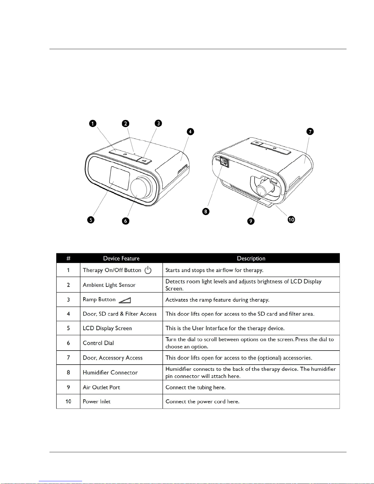
F
IGURE 1-1: DEVICE OVERVIEW AS DESCRIBED IN THE BELOW TABLE
Page 9
PAGE 1-4
1117539, V
ER. 07
1.1 HUMIDIFIER SYSTEM OVERVIEW
The DreamStation Heated Humidifier attaches to the therapy device and provides an air outlet port to connect
a breathing circuit. The breathing circuit is comprised of patient tubing, a mask, and in some instances a
separate exhalation device. The patient tubing can be Respironics heated tubing, 22 mm (non-heated)
performance tubing or 15 mm (non-heated) performance tubing.
The DreamSt ation Heated Humidifie r with Heated Tubing is designed to deliver humidification to provide ad ded
comfort during therapy. This humidification level is controlled through the output of the heated humidifier as
well as the temperature of the optional heated tubing. Use of these two accessories allows for a comfortable
level of humidity to be maintained at the mask.
The DreamStation Heated Humidifier is comprised of the following components:
• Heated Humidifier - The heated humidifier is the primary source of humidification. Humidification
is controlled by adjusting the temperature of the heater plate . The heater plate is then used to hea
water
found in the water tank. This manual includes instructions that explain how to set up an
t
ake care of the heated humidifier . For instructions on how to adjust the heated humidifier settings
refer
to the instructions for use that accompanied the therapy device.
• Water Tank - The water tank stores the water that will be used by the heated humidifier . This man-
ual includes instructions that cover how to use and take care of the water tank.
• Heated Tubing - The heated tubing is an optional accessory that is used, along with the heated
humidifier
ture of the air in order to ensure that it does not cool down pr ior to reaching the mask. This manu
in
cludes instructions that cover how to connect and t ake care of the hea ted tubing. For instruction s
on how to adjust the temperature of the heated tubing, refer to the instructions for use that accompanied the therapy device.
, to control the provided humidification. This is accomplished by controlling the tempera-
d
al
t
,
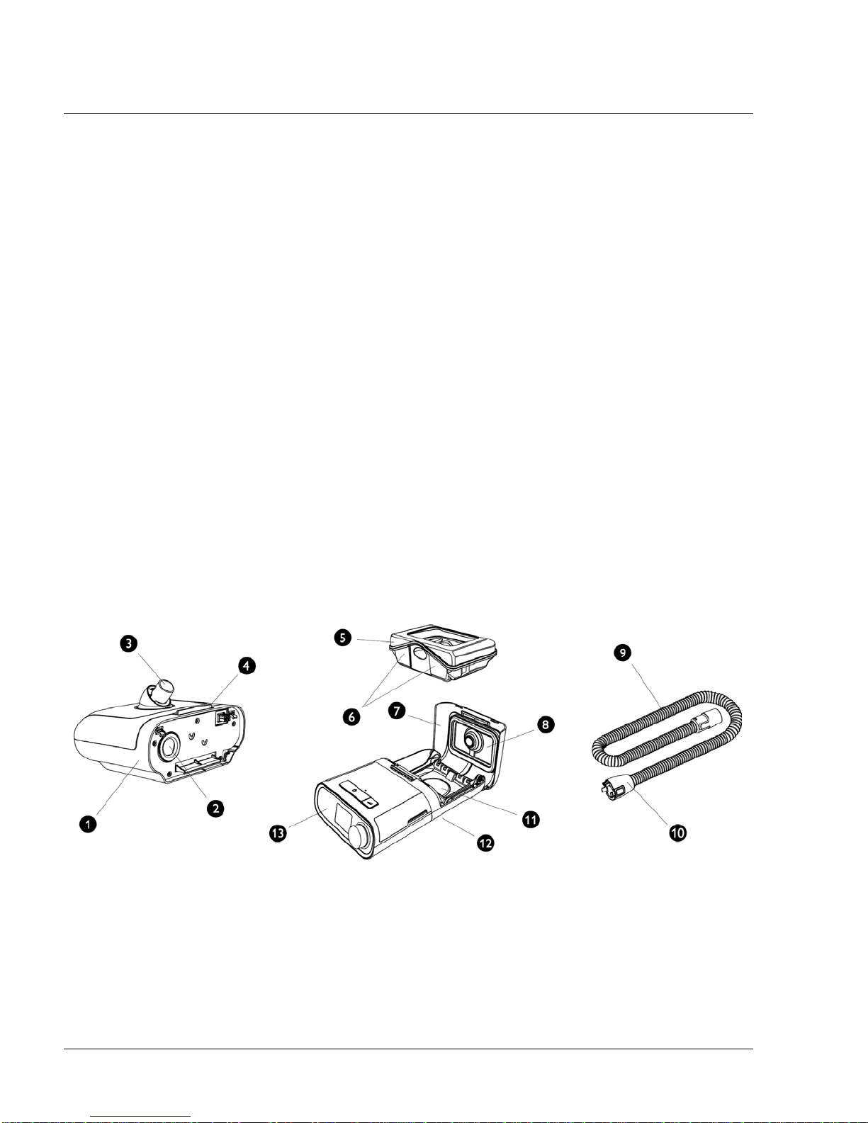
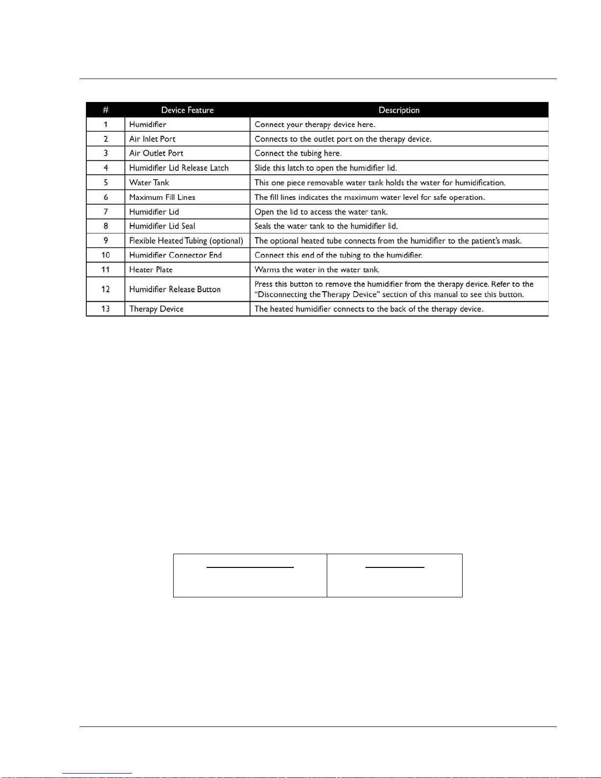
IGURE 1-2: HUMIDIFIER OVERVIEW AS DESCRIBED IN THE FOLLOWING TABLE
F
Page 10
1.2 SERVICE NOTICE
PAGE 1-51117539, VER. 07
The service technician should have a good working knowledge and understanding of the principles of
operation and repair of electro-mechanical sleep therapy devices. By using the most cu rrent version of the
service manual (found on my.respironics.com) and the latest testing software, all repairs and testing can be
performed. If service training is desired, contact the Philips Respironics service location in your area to
schedule training.
1.3 SERVICE TRAINING
Philips Respironics offers service training for the devices. Training includes complete disassembly of the
device, troubleshooting sub-assemblies and components, and necessary safety testing. For more information,
log onto my.respironics.com, and download the Service Training Schedule brochure from the Service Software
and Documentation link.
1.4 PRODUCT SUPPORT STATEMENT
For product support, please contact Philips Respironics Customer Satisfaction.
U.S.A. and Canada
Phone:1-800-345-6443
Fax: 1-800-886-0245
International
Phone: 1-724-387-4000
Fax: 1-724-387-5012
Page 11

PAGE 1-6
This page intentionally blank.
1117539, V
ER. 07
Page 12

PAGE 2-11117539, VER. 07
CHAPTER 2: WARNINGS, CAUTIONS, & NOTES
Warnings, cautions, and notes are used throughout this manual to identify possible safety hazards, conditions
that may result in equipment or property damage, and important information that must be considered when
performing service and testing procedures on the device.
WARNING
Warnings indicate the possibility of injury to people.
CAUTION
Cautions indicate the possibility of damage to equipment.
NOTE
Notes are used to emphasize a characteristic or
important consideration.
Refer to the devices’ User and Provider Manuals for warnings, cautions and notes.
TABLE 2-1: USER & PROVIDER MANUALS
DESCRIPTION PART NUMBER
DreamStation CPAP, User Manual, EN-INTL CE 1121981
DreamStation BiPAP, User Manual, EN-INTL CE 1121982
DreamStation Humid, User Man ual, EN-INTL CE 1121984
DreamStation, Provider Guide, EN-INTL CE 1121983
Page 13

PAGE 2-2
1117539, V
ER. 07
This page intentionally blank.
Page 14

CHAPTER 3: SPECIFICATIONS & CLASSIFICATIONS
Refer to the devices’ User and Provider Manuals for specifications and classifications.
TABLE 3-1: USER & PROVIDER MANUALS
DESCRIPTION PART NUMBER
DreamStation CPAP, User Manual, EN-INTL CE 1121981
DreamStation BiPAP, User Manual, EN-INTL CE 1121982
DreamStation Humid, User Man ual, EN-INTL CE 1121984
DreamStation, Provider Guide, EN-INTL CE 1121983
PAGE 3-11117539, VER. 07
Page 15

PAGE 3-2
1117539, V
ER. 07
This page intentionally blank.
Page 16

PAGE 4-11117539, VER. 07
CHAPTER 4: SETUP
This chapter provides an overview of the system setup including introductory information on the User and
Provider modes and menus. Please refer to the device’s User Manual for further information.
WARNING
• Inspect the power cord often for any signs of damage.
Replace a damaged power cord immediately.
• Be sure to route the power cord to the outlet in a way that
will prevent the cord from being tripped over or interfered
with by chairs or other furniture.
• This device is activated when the power cord is connected.
CAUTION
• If the device has been exposed to either very hot or very
cold temperatures, allow it to adjust to room temperature
(approximately two hours) before beginning setup.
• Do not use extension cords with this device.
NOTE
• Please refer to the Clinical Manual for additional information.
4.0 SUPPLYING DC POWER TO THE DEVICE
A Philips Respironics DC power cord can be used to operate this device in a stationary recreational vehicle,
boat, or motor home. In addition, a Philips Respironics DC battery adapter cable, when used with a DC power
cord, allows the device to be operated from a 12 VDC free-standing battery.
CAUTION
• Always ensure that the DC power cord securely fits into the th erapy device prior to use.
• When DC power is obtained from a vehicle battery, the device should not be used while the
vehicle’s engine is running. Damage to the device may occur.
• Only use a Philips Respironics DC Power Cord and Battery Adapter Cable. Use of any
other system may cause damage to the device.
Page 17
PAGE 4-2
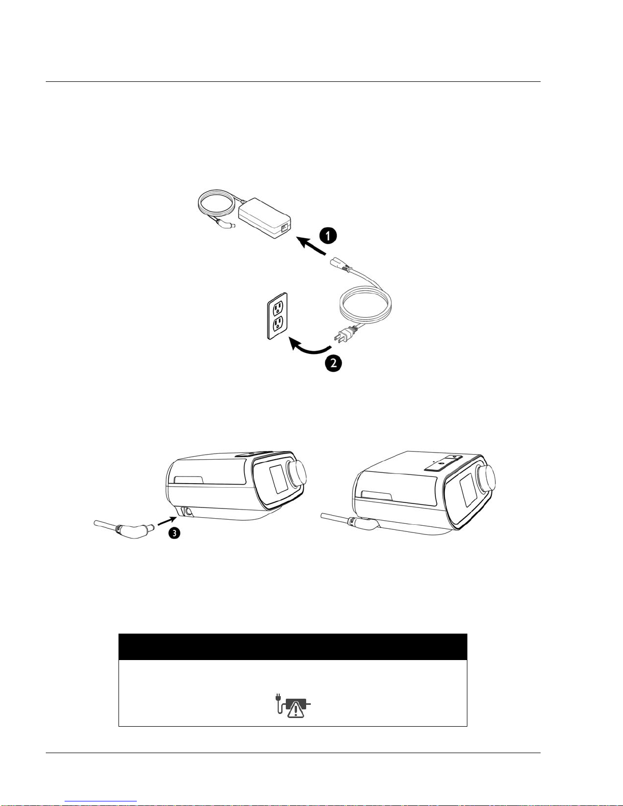
4.1 SUPPLYING AC POWER TO THE DEVICE
Complete the following steps to operate the device using AC power:
1. Plug the socket end of the AC power cord (included) into the power supply (also included).
2. Plug the pronged end of the AC power cord into an electrical outlet that is not controlled by a wall
switch.
.
1117539, V
ER. 07
F
IGURE 4-1: CONNECTING THE AC POWER CORD AND POWER SUPPLY
3. Plug the power supply cord’s connector into the power inlet on the side of the device.
IGURE 4-2: SUPPLYING POWER TO THE DEVICE
F
4. Verify that the plug at the side of the device, at the power supply, and at the electrical outlet are
fully inserted. This will help to ensure that a secure, reliable electrical connection has been made.
NOTE
If the following Incorrect Power Supply icon appears on the screen, please
repeat step 4.
Page 18
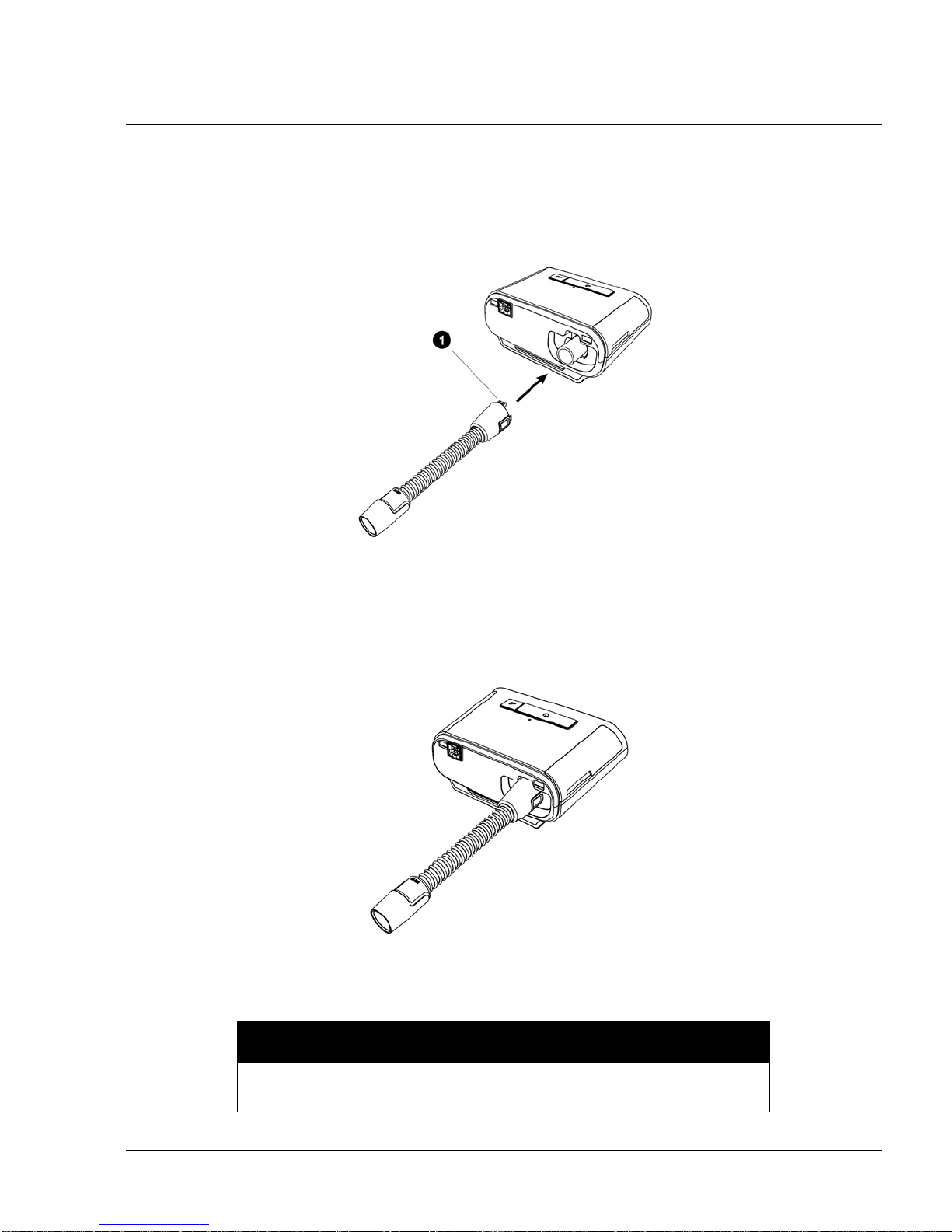
4.2 CONNECTING THE TUBING TO THE PAP DEVICE
To connect the Tubing to the device, complete the following steps:
1. Connect the flexible tubing to the air outlet on the back of the therapy device. Line up the connector (1) at the top of the heated tube to the top of the air out l et por t on th e ba ck of the devic e.
F
IGURE 4-3: CONNECTING THE TUBING TO THE PAP DEVICE
PAGE 4-31117539, VER. 07
2. Press the tubing into place over the air outlet port until the tabs on the side of the tube click into
place in the slots on the sides of the outlet port.
F
IGURE 4-4: TUBING CONNECTED TO THE PAP DEVICE
NOTE
If you are using a standard tube (not shown) instead of a heated tube,
simply slide the tubing over the air outlet port on the therapy device.
Page 19
PAGE 4-4
WARNINGS
• Do not pull or stretch the tubing. This could result in circuit leaks.
• Inspect the tubing for damage or wear. Discard and replace the tubing as
necessary.
• If the device is used by multiple persons (such as rental devices), a low-
resistance, main flow bacteria filter should be installed in-line between the
device and the circuit tubing to prevent contamination.
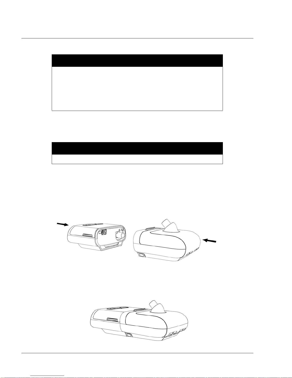
4.3 CONNECTING THE HUMIDIFIER TO THE PAP DEVICE
CAUTION
Do not move the humidifier while the water tank has water in it.
1117539, V
ER. 07
1. Place the therapy device and heated humidifier (with an empty water tank) on a firm, flat surface.
2. Line up the back of the therapy device to the front (top lid release latch side) of the heated humidifier.
3. Make sure the air outlet port on the therapy device lines up with the air inlet port on the humidifier
(not shown).
4. Slide the two units together until they snap into place.
F
IGURE 4-5: CONNECTING THE HUMIDIFIER
5. Make sure that the therap y de vice an d the hu mid ifier are completely seated against each other.
F
IGURE 4-6: HUMIDIFIER CONNECTED
Page 20
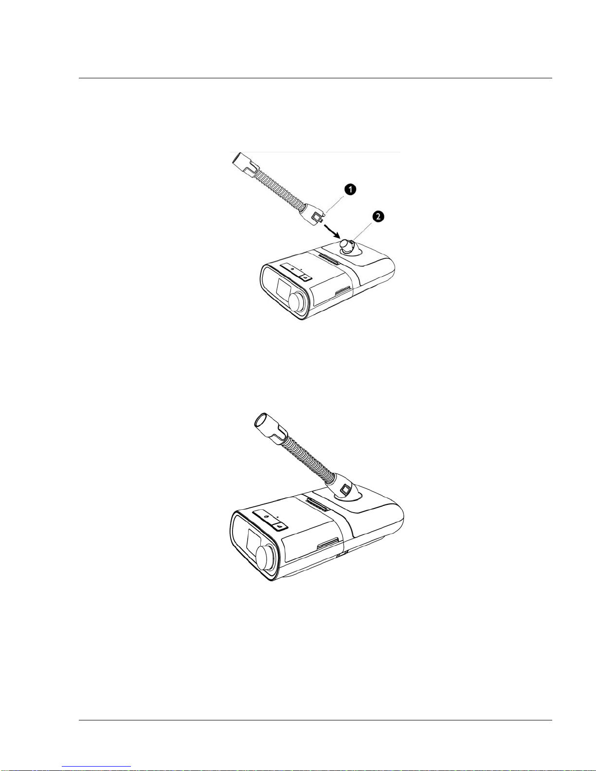
4.4 CONNECTING THE TUBING TO THE HUMIDIFIER
1. To attach the heated tube to the heated humidifier, line up the connector (1) at the top of the
heated tube to the top of the air outlet port (2) on the humidifier.
F
IGURE 4-7: CONNECTING THE TUBING TO THE HUMIDIFIER
PAGE 4-51117539, VER. 07
2. Press the tubing into place over the air outlet port until the tabs on the side of the tube click into
place in the slots on the sides of the outlet port.
IGURE 4-8: TUBING CONNECTED TO THE HUMIDIFIER
F
3. If you are using a standard tube (not shown) instead of a heated tube, simply slide the tubing over
the air outlet port on the heated humidifier.
Page 21
PAGE 4-6
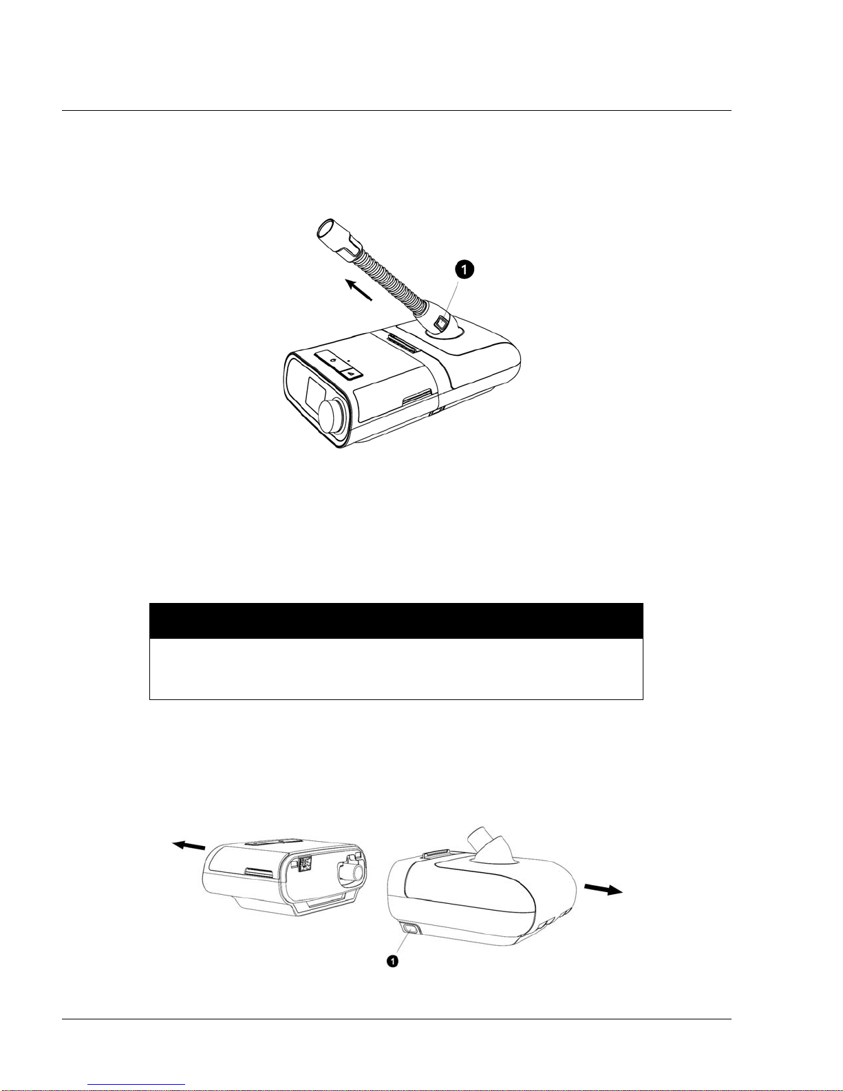
4.5 DISCONNECTING THE TUBING
1. To remove the heated tubing, press in the tabs (1) on the side of the tubing connector and pull the
tubing away from the outlet port.
F
IGURE 4-9: DISCONNECTING THE TUBING
1117539, V
ER. 07
2. If you are using a standard tube (not shown) instead of a heated tube, simply pull the tubing away
from the outlet port.
4.6 DISCONNECTING THE DEVICES
To avoid spilling, do not disconnect the humidifier from the therapy device with
water in the tank. Remove the water tank from the humidifier before
disconnecting the therapy device.
1. Disconnect power to the therapy device.
2. Pick up the system.
3. Place one hand on the therapy device and the other on the humidifier.
4. Press the humidifier release button (1) and pull apart to separate.
CAUTION
F
IGURE 4-10: DISCONNECTING THE DEVICES
Page 22
PAGE 4-71117539, VER. 07
4.7 CHECKING THE HUMIDIFIER LID SEAL
Under normal use, the humidifier lid seal should not require any maintenance or replacement. The seal may be
cleaned as needed by wiping it with a damp cloth. If necessary, the humidifier lid seal may be removed for
further cleaning. Gently peel the seal from the humidifier lid and clean it in a solution of warm water and a mild
liquid dish-washing detergent. Rinse with clean water. Wipe completely on both sides. Allow the seal to air dry.
Inspect the seal for damage. If the humidifier lid seal show signs of wear or damage, it should be replaced.
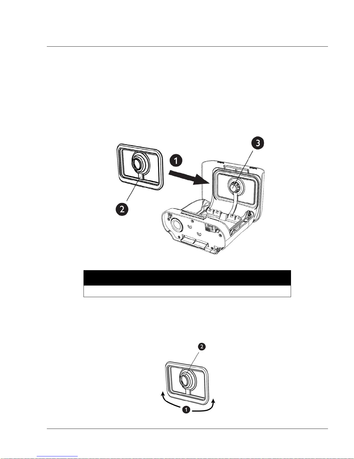
To install or reseat your humidifier lid seal, fully open the humidifier lid. Position the seal (1) against the inside
of the lid so the seal’s center hole aligns with the humidifier outlet port. Confirm that the seal is p ositioned so
the wire channel (2) in the seal is below the humidifier outlet port (3).
F
IGURE 4-11: CHECKING THE HUMIDIFIER LID SEAL
NOTE
The seal only fits properly in one orientation.
With the seal loosely in place, start at the bottom (1) and gently press the edges of the seal into the channel in
the lid of the humidifier. Continue sliding your fingers all around the rectangular perimeter of the seal until the
outer edge is completely seated. Next, press the seal around the humidifier outlet port (2) until the center of the
seal is fully seated. Finally, go back and run your fingers around the rectangular perimeter of the humidifier lid
seal once more to confirm it has not become dislodged.
F
IGURE 4-12: FLIP LID SEAL
Page 23
PAGE 4-8
1117539, V
ER. 07
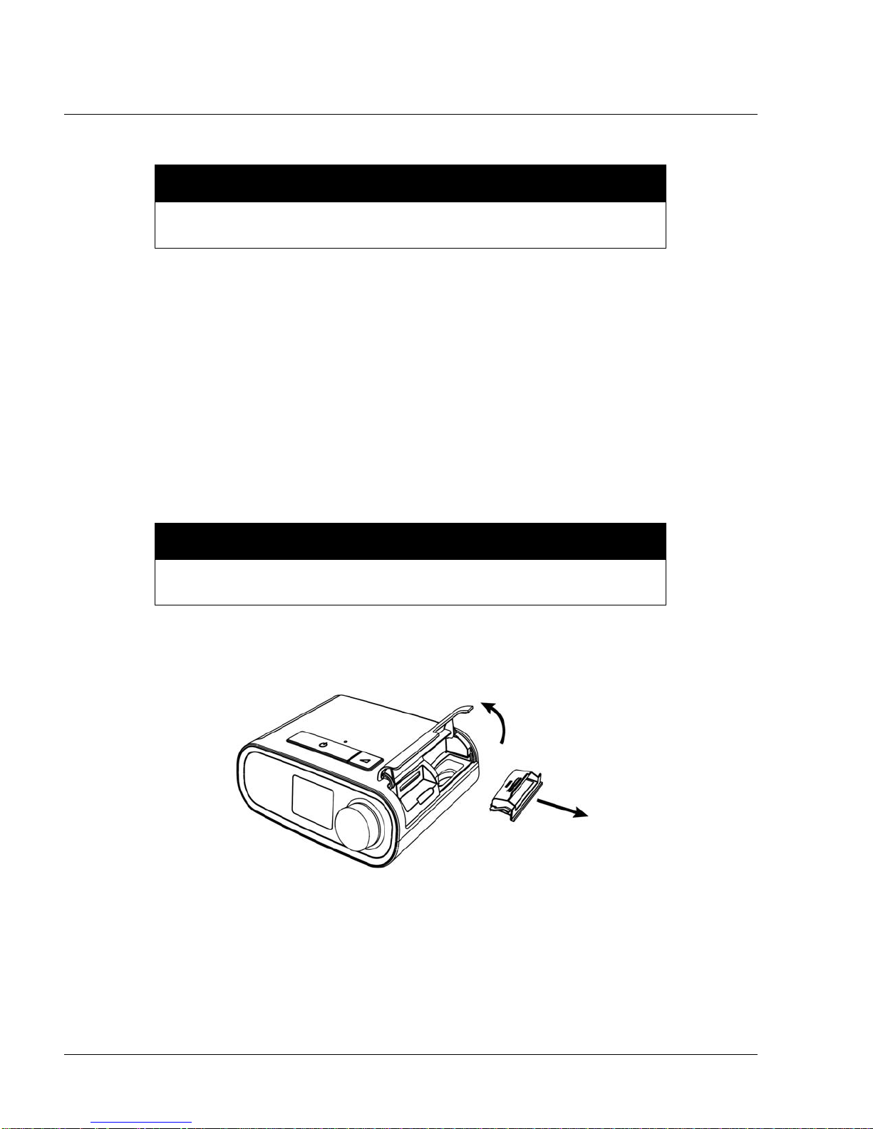
4.8 INSTALLING/REPLACING THE AIR FILTERS
CAUTION
A properly installed, undamaged Philips Respironics blue pollen filter is
required for proper operation.
The device uses a blue pollen filter that is washable and reusable, and a light-blue ultra-fine filter that is
disposable.
The reusable blue filter screens out normal household dust and pollens, while the light-blue ultra-fine filter
provides more complete filtration of very fine particles. The reusable blue filter must be in place at all times
when the device is operating. The ultra-f ine filter is recommended for people who are sensitive to tobacco
smoke or other small particles.
The reusable blue filter is supplied with the device. A disposable light-blue ul tra-fine filter ma y also be include d.
If your filter is not already installed when you receive your device, you must at least install the reusable filter
before using the device.
This device has an automatic air filter reminder. Every 30 days, the device will display a message reminding
you to check your filters and replace them as directed.
NOTE
This message is a reminder only. The device does not detect the performance
of the filters nor does it recognize when a filter has been cleaned or replaced.
1. Lift up on the filter access door and swing open. If replacing, pull out the old filter assembly.
F
IGURE 4-13: REMOVING THE FILTER
Page 24
PAGE 4-91117539, VER. 07
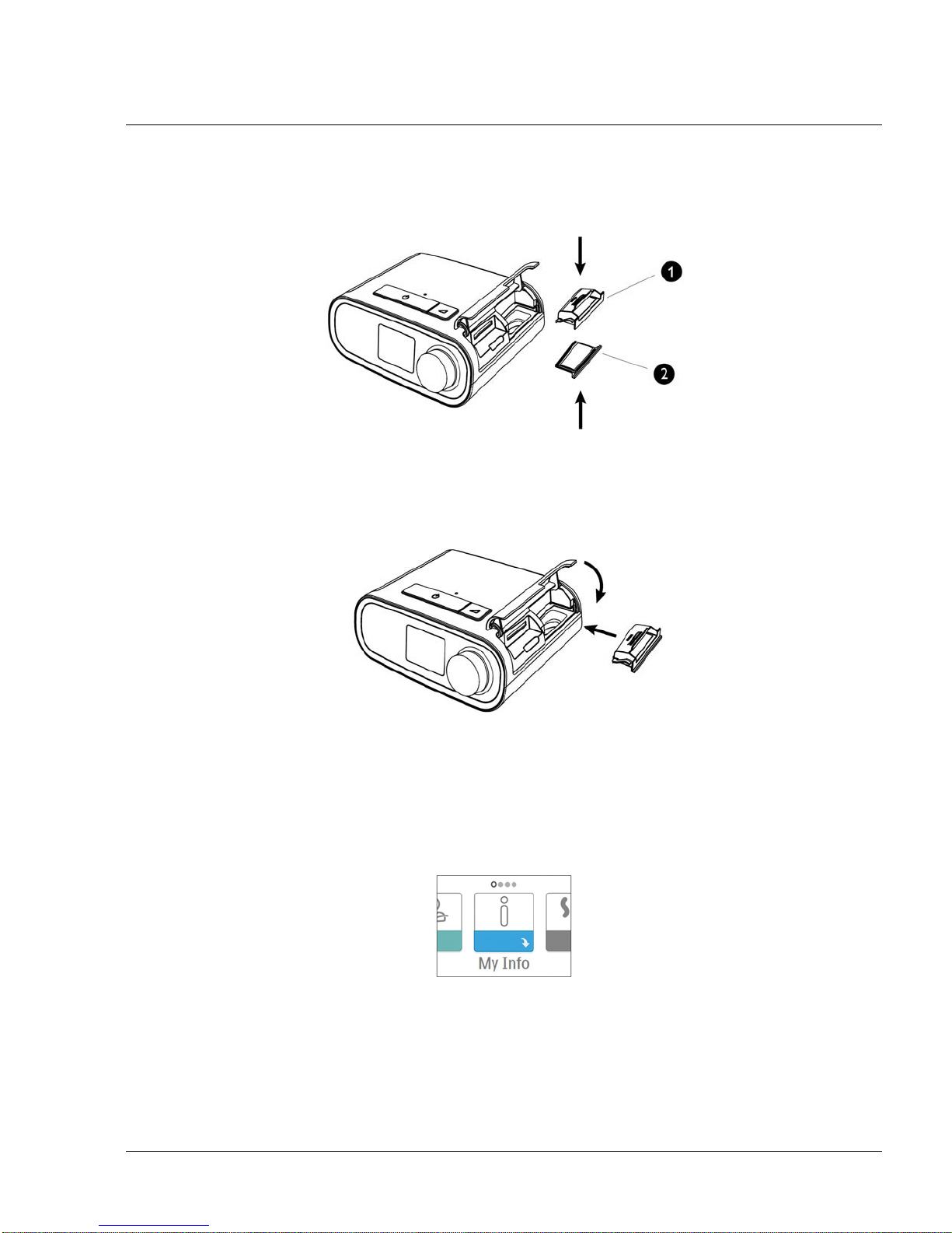
2. If applicable, place a clean, reusable blue pollen filter (1) on top of a new, optional disposable lightblue ultra-fine filter (2) and firmly snap them together.
IGURE 4-14: POLLEN AND ULTRA-FINE FILTERS
F
3. Place the new filter assembly back in the side of the therapy device. Swing the door closed.
IGURE 4-15: INSTALLING THE FILTER
F
4.9 STARTING THE DEVICE
1. Ensure power is supplied to the device. The first screen to display will be the Philips Respironics
logo, followed by the device model screen, and then the Home screen.
F
IGURE 4-16: HOME SCREEN
The first time the device is powered on, a pop-up will prompt you to set the time on the device. The default
setting is Greenwich Mean Time, but you may adjust the ti m e in 30 minute in creme nts to match your local time
zone. If you choose to skip this initial time setting, the time can always be adjusted under the “My Setup” menu.
Note: This time setting is not displayed as a clock function on the device. It is only used to align
therapy data for Provider’s data reports.
Page 25

PAGE 4-10
2. Press the Therapy button on top of the device to turn on airflow and begin therapy. The current
delivered pressure will display on the screen.
3. Make sure that no air is leaking from the system.
4. Press the Therapy button again to turn off therapy.
NOTE
During therapy, it there is a mains interruption (i.e. power loss) the device will
return to the Home screen once power is restored. You may resume therapy a s
needed.
4.10 NAVIGATING THE DEVICE SCREENS
NOTE
The display is not a touch screen. You must use the control dial to navigate the
device menu.
1117539, V
ER. 07
The User Interface (UI) on this device allows you to adjust the device settings and view information about your
therapy. The UI is comprised of the display screen and the control dial. Rotate the control dial in either di rection
to scroll through the menu options on the display screen.
To adjust a setting:
1. Rotate the control dial to your desired menu option.
2. Press the control dial to select that setting.
3. Rotate the control dial to change the setting.
4. Press the control dial ag ain to sav e th e cha n ge.
.
NOTES
•
The rotate dial icon on any screen indicates to rotate the dial to perform
an action. The click dial icon
perform an action.
on any screen indicates to press the dial to
• Pressing the dial when the down arrow appears on any screen will take
you to a sub-menu with more menu options. Pressing the dial when the up
arrow
appears on any sub-menu will return you back to the main menu.
• The screens shown throughout this manual are examples for reference
only. Actual screens may vary based upon device model and provider
settings.
Page 26
PAGE 4-111117539, VER. 07
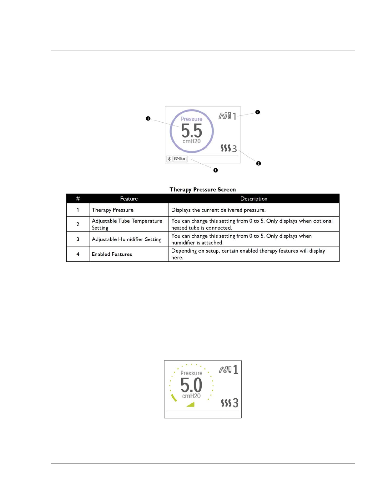
4.10.1 USER MENU NAVIGATION (THERAPY ON) AND OPTIONAL HUMIDIFICATION SETTINGS
While the device is delivering therapy, you can adjust Tube Temperature or Humidifier Settings . Rotate the
control dial to choose either setting. Press and rotate the dial to change the setting.
Note: If you are using the Humidifier without the Heated Tube, simply just rotate the control dial to change the
Humidifier setting.
F
IGURE 4-17: THERAPY PRESSURE SCREEN
Ramp Feature
The device is equipped with an optional ramp feature that can be enabled or d isabled. Th is feature reduces the
air pressure when you are trying to fall asleep and then gradually increases (ramps) the pressure until your
prescription setting is reached, allowing you to fall asleep more comfortably.
If ramp is enabled on your device, after you tur n on the ai rflow, press the Ramp button on the top of the device.
You can use the Ramp button as often as you wish during the night.
When you click the ramp button, the Therapy screen will change to reflect the Ramp pressure, and the green
circle will reflect the gradual increase in pressure.
F
IGURE 4-18: RAMP PRESSURE SCREEN
The device has two ramp modes. The standard ramp mode increases pressure at a steady rate. Alternately,
the SmartRamp mode maintains a constant lower pressure until the device detects that you require more
pressure.
Page 27
PAGE 4-12
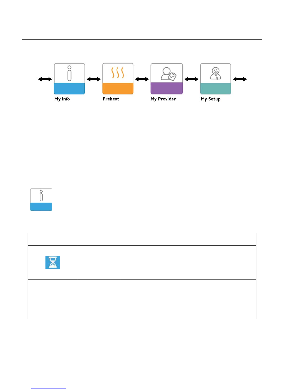
4.10.2 USER MENU NAVIGATION (THERAPY OFF)
From the Home screen, you can scroll between the following four options:
F
IGURE 4-19: USER MENU (THERAPY OFF)
• My Info: This menu provides summary statistics of your therapy use.
• Preheat: This function lets you warm up your humidifier for 30 minutes before starting a therapy
session.
• My Provider: This menu contains informatio n that the provider may direct the user to r ead to them
so they can better assist them over the phone.
• My Setup: This menu contains comfort settings that you can adjust as needed.
1117539, V
ER. 07
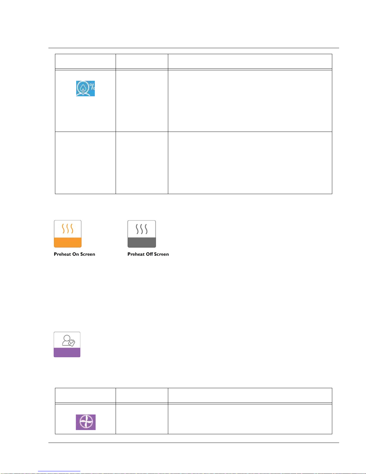
My Info:
When you select “My Info”, you will be able to view the following screens. You cannot change settings in the
Info menu. These screens are only for reference.
ICON TEXT DESCRIPTION
Therapy Hours This screen displays the amount of time the user is actually
receiving therapy on the device for the most recent 1 day
time frame. It also displays the average amount of time the
patient is actually receiving therapy over the last 7 days and
30 days.
AHI AHI This screen displays the nightly Apnea/Hypopnea indices
(AHI) value for the most recent 1 day time frame. It also
displays the average of these individual nightly AHI values
over a 7 day and a 30 day time frame. This screen only
displays if your home care provider has enabled it. Only
available on CPAP Pro and Auto CPAP devices.
Page 28
ICON TEXT DESCRIPTION
Mask Fit Displays the value “100% minus Large Leak”. Large Leak is
the percentage of time that the mask leak was so high that it
is no longer possible for the device to identify respiratory
events with statistical accuracy. Displays the value for the
most recent 1 day, as well as the values over last 7 days
and 30 days. This screen only displays if your home care
provider has enabled it. Only available on CPAP Pro and
Auto CPAP devices.
PAGE 4-131117539, VER. 07
Periodic
Breathing
Preheat:
When using a humidifier, the device can preheat the water tank for up to 30 minutes prior to starting therapy. In
order to activate the preheat mode, the blower must be “off” and a humidifier must be attached. When
“Preheat” is selected, you will be able to turn the control dial to choose between “on” or “off”. Press the control
dial again to make your selection. During the 30 minute preheat, you will still be able to use the control dial to
select other menu options from the Home screen.
Note: This screen only displays when a humidifier is attached.
Periodic
Breathing
Displays the percentage of time that the user exp erienced
periodic breathing. Displays the value for the most recent 1
day time frame, as well as values for the last 7 days and 30
days. If you observe a large increase in the percent of time
in periodic breathing indicated her, contact your home care
provider for assistance. This screen only displays if your
home care provider has enabled it. Only availa b le on CPAP
Pro and Auto CPAP devices.
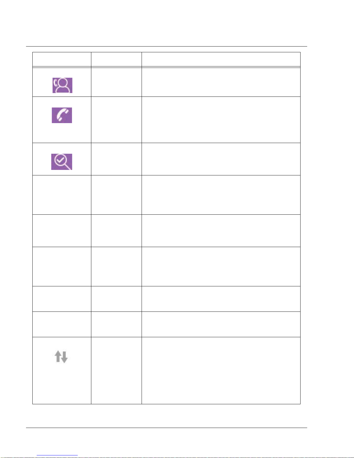
My Provider:
When you select “My Provider”, you will be able to view the following screens. You cannot change settings in
the Provider menu.These screens are only for reference.
ICON TEXT DESCRIPTION
Device Info This screen displays your therapy device information: serial
number, model and software version.
Page 29
PAGE 4-14
ICON TEXT DESCRIPTION
1117539, V
ER. 07
Provider Contact
Info
This screen will display the contact information for your
provider if it has been uploaded to your device.
Phone-In This screen displays the total therapy hours for the device,
the total blower hours, the total number of days used when
the sessions were greater than 4 hours, and a compliance
check number used by your home care provider to validate
that the data provided by you is the data taken from this
screen.
Compliance This screen displays your start date, the total number of
days used when the sessions were greater than 4 hours,
and a check code number used by your home care
provider.
VIC90 VIC 90 This Visual Inspection Check screen will display a check
code number created from information gathered over the
most recent 90 day period. This 15 digit number will display
as: xxx.xxxx.xxxx.xxxx. Your home care provider may
periodically ask you for this information.
A-TRIAL A-Trial If Auto-Trial mode is available, this screen displays Days:
xx/xx (where xx/xx is the number of accumulated trial days /
number of selected trial days). Available on the Pr o, Auto,
BiPAP Pro, and BiPAP Auto models.
90%
Pressure
IPAP: 90%
Pressure
EPAP: 90%
Pressure
90% Pressure This screen displays the nightly value of 90% Pressure for
the most recent 1 day time frame. It also displays the
average of these individual nightly values of 90% Pressure
over a 7 day and a 30 day time frame. Availab le on the Auto
model.
IPAP: 90%
Pressure
Displays the value of 90% inhalation pressure for the mo st
recent 1 day, as well as the average values over the last 7
days and 30 days. Available on the BiPAP Auto model.
EPAP: 90%
Pressure
Displays the value of 90% exhalation pressure for the most
recent 1 day, as well as the average values over the last 7
days and 30 days. Available on the BiPAP Auto model.
Upload Allows user to initiate a modem call when an optional
Cellular or Wi-Fi Accessory is installed. After the modem
upload has finished, the screen will either display a green
checkmark with the text “Completed” to indicate a
successful upload, or a red X with the text “Failed” to
indicate an unsuccessful upload. If the upload fails, initiate
an upload a second time, or contact your home care
provider if the issue persists. This screen is locked if
modem is off.
Page 30
ICON TEXT DESCRIPTION
PAGE 4-151117539, VER. 07
Performance
Check
My Setup:
When you select “My Setup”, you will be able to view the following screens. Y ou can change the settings in the
Setup menu. These screens will only display if they are available and enabled on the device.
Your device is equipped with a self-diagnostic tool called
“Performance Check.” This tool can evaluate your device
for certain errors. It also allows you to share key device
settings with your home care provider. Use Performance
Check when directed to by your home care provider.
At conclusion of the scan, the screen displays a green
checkmark if no issue is detected. If device displays a red
“X”, please contact your home care provider for assistance.
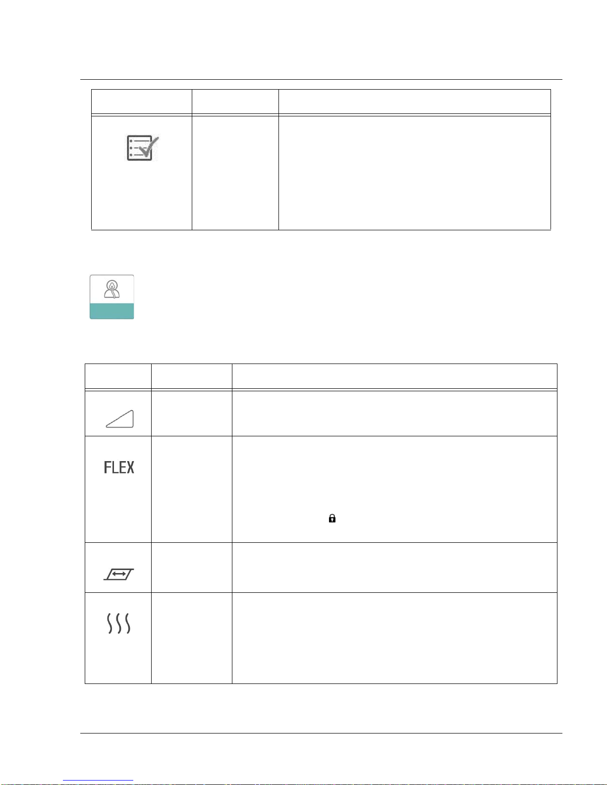
ICON TEXT DESCRIPTION
Ramp This dis plays t he ram p starting pr essu re. You can increase or decrease
the ramp starting pressure in 0.5 cm H2O increments.
Flex This allows you to adjust the level of air pressure relief that you feel
when you exhale during therapy. Your home care provider can enable
or disable this feature. When your provider enables Flex, a level will
already be set for you on the device. You can increase or decrease the
setting from 1 to 3. The setting of “1” provides a small amount of
pressure relief, with higher numbers providing additional relief.
Note: If a lock icon
provider has locked this setting and you cannot change it.
Rise Time Rise time is the time it takes for the device to change from EPAP to
IPAP. This screen allows you to adjust the rise time so you can find the
desired setting.
Humidification This displays the Humidification Mode being used. You can choose
between Fixed or Adaptive Humidification. If a heated tube is being
used, the device will automatically switch to Heated Tube Humidification
Mode. A “lock” symbol will appear next to the mode setting indicating
that so long as the heated tube is attached to the device, this mode
cannot be changed. However, the heater plate and tube temperature
settings can still be adjusted on the device Therapy screen as normal.
is displayed on this screen, it indicates that yo ur
Page 31

PAGE 4-16
ICON TEXT DESCRIPTION
Mask Type This setting allows you to adjust the level of air pressure relief based on
the specific Philips Respironics mask. Each Philips Respironics mask
may have a “System One” resistance control setting. Contact your
home care provider if you cannot find this resistance setting for your
mask.
Note: If a lock icon
provider has locked this setting and you cannot change it.
Tube Type This setting allows you to select the correct size diameter tubing that
you are using with the device. You can choose either (22) for the Philips
Respironics 22 mm tubing, or (15) for the Philips Respironics 15 mm
tubing. When using Heated T ubing, the device will automatically change
this setting to the appropriate tubing type (15H) and you will not be able
to change it.
Note: Tubing is identified on the cuff with the tubing identifier symbol:
“15”, “22” or “15H”.
Note: If a lock icon is displayed on this screen, it indicates that your
provider has locked this setting and you cannot change it.
Language This feature allows you to choose which language to display on the
interface. You can also turn off (0) text mode which means the device
will display the “Icon Mode” on the interface.
is displayed on this screen, it indicates that your
1117539, V
ER. 07
Check Mask Fit This feature allows you to check the fit of your mask prior to starting
therapy. This is done by measuring the amount of leak.
Modem Allows you to turn modem off temporarily or turn it back on. When
modem is turned off, it will automatically turn on again after 3 days. Only
displays when modem is installed.
Bluetooth Allows you to turn Bluetooth off and on. Also, it allows you to clear the
pairing with a compatible Bluetooth device.
Time Allows you to adjust the time. The default setting is Greenwich Mean
Time, but you may adjust the time in 30 minute increments to match
your local time zone.
Note: This time setting is not displayed as a clock function on the
device. It is only used to align your therapy data for your Provider’s data
reports.
Page 32

PAGE 4-171117539, VER. 07
Check Mask Fit
The optional check mask fit feature can be enabled or disabled by the home care provider. This feature allows
you to check the fit of your mask prior to startin g ther apy. This is done by measuring the amount of leak. Put on
your mask assembly. Refer to your mask instructions if needed. Navigate to the Check Mask Fit screen under
“My Setup” and press the control dial to initiate the check.
The device will deliver a test pressure while the screen counts down 40 seconds. A green bar indicates good
fit, while a red bar indicates improvement is needed. After the test, normal therapy will start and the screen will
either display a green checkmark or a red “X”. The green checkmark indicates that the leak found allows for
optimal performance of the device. The red “X” indicates that the leak may affect device performance,
however, the device will remain functional and deliver therapy.
F
IGURE 4-20: CHECK MASK FIT SCREEN
Sleep Progress
The device provides summary information about therapy use each time the therapy is turned off. The first
screen displays “Three Night Summary.” It shows nightly usage for the last 3 sleep sessions (measured in 24
hour periods, ending at noon each day). The most recent session is displayed in the right hand bar, labeled
with the number of hours slept. A green bar indica tes that the per son sle pt more tha n 4 hour s, and a yellow bar
indicates less than 4 hours of use.
The second screen shows the total number of 4+ hour nights that the person had slept in the last 30 days. It
provides a goal of sleeping at least 4 hours per night for 70% of the last 30 nigh ts. Therefore the goal is 21
“good nights” of use. This screen provides a simple way to track progress. The screen will stop displaying
when the goal is reached, or after the first 90 days of use has passed, whichever comes first.
Altitude Compensation
This device automatically compensates for altitude up to 7,500 feet. No manual adjustment is necessary.
Page 33

PAGE 4-18
1117539, V
4.10.3 ACCESSING PROVIDER MODE SCREENS
Accessing provider mode unlocks settings that cannot be modified by the user. To access provider mode:
1. Supply power to the device. First, plug the socket end of the AC power cord into the power sup ply.
Then plug the pronged end of the AC power co rd in to a n electrical o utlet that is not controlled b y a
wall switch. Finally, plug the power supply cord’s connector into the power inlet on the back of the
device.
2. Once the device is powered, press and hold both the control dial and the Ramp button on the
device for at least 5 seconds.
3. Y ou are now in provider mode. You can choose between the following Provider mode screens.
4.10.4 NAVIGATING THE PROVIDER MODE SCREENS
The following sections will describe the options available from the Provider screens:
ER. 07
Therapy Settings:
Choosing this screen will take you to a sub-menu where you can adjust the device therapy modes and
pressure settings. These settings are described here.
F
IGURE 4-21: SAMPLE THERAPY SUB-MENU
Note: Not all settings shown here will display on the device. The display will vary based on therapy device
model and device settings.
Page 34

ICON TEXT DESCRIPTION
PAGE 4-191117539, VER. 07
CPAP
C-Check
Auto
Bi-Level
AutoB
Opti-Start Opti-Start This feature starts an Auto-CPAP therapy session at a starting
EZ-Start EZ-Start This feature reduces the therapy pressure setting for the first
Mode This screen displays the therapy mode setting. Depending on
the therapy device model, you can select CPAP mode, CPAPCheck (C-Check) mode, Auto-CPAP (Auto) mode, Bi-Level
mode, or Auto Bi-Level (AutoB) mode.
Note: CPAP-Check mode (C-Check) delivers CPAP therapy
while automatically adjusting the pressure level to meet
patient needs over the long term. Every 30 hours of therapy
use, the therapy device evaluates patient obstructive
respiratory disturbance index (ORDI) and increments pressure
± 1 cm H2O if needed. The range of adjustment that can be
made over time is limited to ± 3 cm H2O of the CPAPCheck
pressure setting, in 1 cm H2O increments.
pressure that is closer to the previous session’s 90%
pressure, in order to reduce the likelihood of any residual
events at the beginning of a therapy session. You can enable
or disable this feature.
few days of operation and gradually increases this setting until
the prescription therapy pressure is reached. The initial
pressure will be half of the prescription pressure, but no lower
than 5 cm H2O. After each day of successful use (the session
was greater than 4 hours), the therapy pressure will increase
by 1 cm H2O until the prescription pressure is reached.
From that point forward, the therapy device would operate in
normal CPAP or CPAP-Check mode. If the patient has not
reached their prescription pressure after 30 days of EZ-Start,
then the therapy pressure will increase by 1 cm H2O per day
until the prescription pressure is reached. You can enable or
disable EZ-Start only if CPAP or CPAP-Check mode is
enabled.
A-TRIAL A-Trial This Auto-Trial feature will enable the device to deliver Auto-
A-Trial Days This screen allows you to adjust the duration of the Auto-Trial
Auto Min This screen allows you to modify the Auto minimum pressure
CPAP therapy for a selectable number of days of patient use.
You can enable or disable this feature.
feature in number of days. You can set this from 3 to 30 days.
The default is 7 days. This setting only displays if Auto-Trial
mode is available and enabled. When you reach the last
available Auto-Trial period, the text for this selection will
appear in red font.
setting. You can adjust this setting from 4 cm H2O to the Auto
maximum pressure setting. This setting only displays if AutoCPAP mode is enabled or if the Auto-Trial feature is available
and enabled.
Page 35

PAGE 4-20
1117539, V
ICON TEXT DESCRIPTION
Auto Max This screen allows you to modify the Aut o maximum pressu re
setting. You can adjust this setting from the Auto minimum
pressure setting to 20 cm H2O. This screen only displays if
Auto-CPAP mode is enabled or if the Auto-Trial feature is
available and enabled.
cmH
O Pressure This screen allows you to adjust the CPAP pressure, or the
2
IPAP IPAP This screen allows you to modify the IPAP setting. The initial
EPAP EPAP This screen allows you to modify the EPAP setting. The initial
CPAP-Check mode starting pressure. If Auto-Trial mode was
used, you can choose the 90% pressure setting determined
from the Auto-Trial mode, or you can adjust this setting from 4
to 20 cm H2O. If the Auto-Trial mode was not used, this
screen allows you to only adjust the pressure setting from 4 to
20 cm H2O.
default setting is 20 cm H2O. You can adjust the setting from
the EPAP setting to 25 cm H2O. This screen only displays if
Bi-level mode is enabled.
default setting is 4 cm H2O. You can adjust the setting from 4
cm H2O to the IPAP setting. This screen only displays if Bilevel mode is enabled.
ER. 07
IPAP Max This screen allows you to modify the Maximum IPAP setting.
The setting you specify here will be the maximum level of
pressure applied during the inspiratory breath phase. You may
adjust the setting from the Minimum EPAP setting to 25 cm
H2O. This screen only displays if Auto Bi-level mode is
enabled.
EPAP Max This screen allows you to modify the Minimum EPAP setting.
The setting specified here will be the minimum level of
pressure applied during the expiratory breath phase. You may
adjust the setting from 4 cm H2O to the Maximum IPAP
setting. This screen only displays if Auto Bi-level mode is
enabled.
PS Min This screen allows you to modify the Minimum Pressure
Support setting. This setting is the minimum difference that is
permitted between IPAP and EPAP while Auto
Bi-level therapy mode is active. You may adjust the setting
from 0 cm H2O to the Maximum Pressure Support setting.
This screen only displays if Auto Bi-level mode is enabled.
PS Max This screen allows you to modify the Maximum Pressure
Support setting. This setting is the maximum difference that is
permitted between IPAP and EPAP while Auto Bi-level therapy
mode is active. You may adjust the setting from 0 cm H2O to
the minimum value of either 8 cm H2O, or the difference
between Max IPAP and Min EPAP. This screen only displays if
Auto Bi-level mode is enabled.
Page 36

PAGE 4-211117539, VER. 07
Comfort Settings:
Choosing this screen will take you to a sub-menu where you can adjust the humidification and pressure
comfort settings. These settings are described here.
IGURE 4-22: SAMPLE COMFORT SUB-MENU
F
Note: Not all settings shown here will display on the device. The display will vary based on therapy device
model and device settings.
ICON TEXT DESCRIPTION
Humidification This setting allows you to select the Humidification Mode
being used. You can choose between Fixed or Adaptive (A)
Humidification. If a heated tube is attached to the device, then
the device will automatically switch to Heated Tube
Humidification Mode.
Fixed mode applies a constant heat on the humidifier heater
plate. Under certain conditions and settings, this mode can
allow condensation to occur in the tube.
Adaptive mode adapts the heater plate temperature to the
ambient conditions in the room, and is designed to not allow
condensation to occur in the tube.
Humidifier This setting allows you to choose the desired humidity setting
for the humidifier: 0, 1, 2, 3, 4 or 5.
Tube
Temperature
This setting allows you to choose the desired temperature for
the heated tube: 0, 1, 2, 3, 4 or 5.
Page 37

PAGE 4-22
ICON TEXT DESCRIPTION
SmartRamp When SmartRamp mode is enabled, the therapy device’s
ramp function utilizes an Auto titrating algorithm during the
ramp period. It allows patients the ability to stay at lower
pressures during the ramp period, to improve their acclimation
to therapy.
SmartRamp mode functions differently, depending on the
therapy mode that the device is using.
*In CPAP or CPAP-Check mode, the SmartRamp applies the
Auto-CPAP algorithm during the ramp period. The Ramp Start
pressure becomes the Auto Minimum pressure during the
ramp period. The Auto Maximum pressure during ramp is the
CPAP or CPAP-Check pressure.
*In Auto mode, the SmartRamp applies the Auto-CPAP
algorithm during the ramp period. The Ramp Start pressure
becomes the Auto Minimum pressure during the ramp period.
The Auto Maximum pressure during ramp is the Auto
Minimum under normal Auto mode.
*In BiPAP or Auto-BiPAP mode, the SmartRamp applies the a
modified version of the Auto-BiPAP algorithm during the ramp
period. The Ramp Start pressure becomes the EPAP
Minimum pressure, and the Pressure Support Minimum
pressured is applied.
The IPAP Maximum pressure during ramp is the EPAP or
EPAP Minimum under normal BiPAP or Auto-BiPAP mode.
The SmartRamp period will terminate in either of two ways:
1) If SmartRamp pressure reaches the minimum pressure of
the therapy mode selected, then SmartRamp ends, and the
device continues to deliver therapy under the selected therapy
mode, or:
2) If SmartRamp pressure does not reach the minimum
pressure of the therapy mode selected by the end of the
Ramp Time, then pressure is increased at a rate of
approximately 1 cm H2O per minute. Once the pressure
reaches the minimum pressure of the therapy mode selected,
then the device will continue to deliver therapy for that mode.
If SmartRamp mode is not enabled, then the standard, linear
pressure ramp mode is active.
1117539, V
ER. 07
Ramp Time When you set the Ramp time, the device increases the
therapy pressure from the value set on the Ramp start screen
to the therapy pressure setting over the length of time
specified here. If the therapy pressure is set to 4 cm H2O (the
minimum setting), this screen will not display.
Note: Depending on the therapy mode, the therapy pressure
setting could be CPAP pressure, CPAP-Check pressure, Auto
min pressure, EPAP pressure, or EPAP min pressure.
Note: If the Ramp time is set to 0, Ramp start will not display.
Page 38

ICON TEXT DESCRIPTION
Ramp Start This displays the Ramp starting pr essure . You can increase or
decrease the Ramp starting pressure in 0.5 cm H2O
increments. This is only available if Ramp time has been set to
>0 and therapy pressure >4 cm H2O.
Note: Depending on the therapy mode, the therapy pressure
setting could be CPAP pressure, CPAP-Check pressure, Auto
min pressure, EPAP pressure, or EPAP min pressure.
Flex This screen displays the comfort mode setting. You can select
None, C-Flex, or C-Flex+ (if in CPAP or CPAP-Check mode).
You can select None, C-Flex, or A-Flex (if in Auto-CPAP or
Auto-Trial mode).
Flex Setting You can modify the Flex setting (1, 2 or 3) on this screen if you
enabled Flex. The setting of “1” provides a small amount of
pressure relief, with higher numbers providing additional relie f.
Flex Lock This enables you to lock the Flex setting if you do not want the
patient to change it.
PAGE 4-231117539, VER. 07
Rise Time Rise time is the time it takes for the device to change from
EPAP to IPAP. This screen allows you to adjust the rise time
so you can find the desired setting. This is only available if
Flex has been disabled and the device is in Bi-level or Auto Bilevel mode.
• 0 (off) reduces the Rise Time feature to the lowest setting
(off = 150 msec).
• 1 sets Rise Time to 1 (200 msec).
• 2 sets Rise Time to 2 (300 msec).
• 3 sets Rise Time to 3 (400 msec).
Rise Time Lock This enables you to lock the Rise Time setting if you do not
want the patient to change it.
Tube Type This setting allows you to select the correct size diameter
tubing that you are using with the device. You can choose
either (22) for the Philips Respironics 22 mm tubing, or (15) for
the Philips Respironics 15 mm tubing. When using Heated
Tubing, the device will automatically change this setting to the
appropriate tubing type (15H).
Tube Type Lock This enables you to lock the Tubing type setting for either the
15 mm or the 22 mm tubing if you do not want the patient to
change it.
Page 39

PAGE 4-24
ICON TEXT DESCRIPTION
Mask Type This setting allows you to select the appropriate Mask Type
resistance setting (also known as System One Resistance
Control) for your Philips Respironics mask. This feature allows
the device to adjust the level of pressure compensation to
match your mask. Refer to the packaging of your mask to
identify the resistance setting for your mask.
Note: It is important to use the appropriate “Mask Type”
resistance setting to ensure proper pressure delivery to the
patient.
Mask Type Lock This enables you to lock the Mask Type resistance setting if
you do not want the patient to change it.
Check Mask Fit You can enable or disable the check mask fit setting. This
feature allows the patient to check the fit of their mask prior to
starting therapy. This is done by measuring the amount of leak
in the patient circuit.
1117539, V
ER. 07
Device Settings:
Choosing this screen will take you to a sub-menu where you can adjust the way the device displays
information. These settings are described here.
F
IGURE 4-23: SAMPLE DEVICE SUB-MENU
Note: Not all settings shown here will display on the device. The display will vary based on therapy device
model and device settings.
Page 40

ICON TEXT DESCRIPTION
PAGE 4-251117539, VER. 07
AHI Show
AHI/Fit/PB
You can select whether or not the Apnea/Hypopnea index,
Mask Fit averages, and Periodic Breathing averages are
displayed on the Patient Info screens.
cmH
O Pressure Units If enabled on the device, you will have the option to choose
2
the units of pressure that are displayed. You can choose
between “cm H2O” or “hPa”.
Automatic On You can enable or disable this feature if you want the device
to automatically turn the airflow on whenever the patient
applies the interface (mask) to their airway.
Automatic Off You can enable or disable this feature if you want the device
to automatically turn the airflow off whenever the patient
removes the interface (mask) from their airway.
Language This feature allows you to choose which language to display
on the interface. You can choose English or Spanish.
Clear Default
Reminders
This setting turns off the default patient reminders that are
enabled in the therapy device from the factory.
Note: This does not turn off additional reminders that you
may have activated in Encore. Encore messages must be
cleared or modified in Encore.
Reset Data Use the Reset Data function to clear patient data from the
therapy device, as well as an SD card and modem (if
installed). After you click to execute Reset Data, the device
will display a message asking you to confirm the reset. Click
again to reset data in the device.
Note: Reset Data resets Blower Hours that are visible to the
patient, but it does not reset Machine Hours in the Provider
Menu.
Page 41

PAGE 4-26
1117539, V
ER. 07
Info Screens:
Choosing this screen will take you to a sub-menu where you can view information on patient usage. These info
screens are described here.
Note: Not all the screens shown here will display on the device. The display will vary based on therapy device
model and device settings.
ICON TEXT DESCRIPTION
Phone In This screen displays the total therapy hours for the device, the
total blower hours, and the total number of days used when the
sessions were greater than 4 hours since the device was last
reset. This screen also displays a compliance check number
you can use to validate that the data provided to you is the da t a
taken from this screen.
Compliance This screen displays the start day and the total number of days
used when the sessions were greater than 4 hours. This
screen also displays a check code number you can use to
validate that the data provided to you is the dat a taken fr om this
screen.
VIC90 VIC90 This Visual Inspection Check screen will display a check code
number created from information gathered over the most
recent 90 day period. This 15 digit number will display as:
xxx.xxxx.xxxx.xxxx.
Days>4 Days Greater
Than 4
This screen displays the cumulative number of device therapy
sessions that exceeded 4 hours over a 1 day, a 7 day, and a 30
day time frame.
Therapy Hours The device is capable of recognizing the difference between
the time the patient is actually receiving therapy and the time
when the blower is simply running. This screen displays the
amount of time the patient is actually receiving therapy on the
device for the most recent 1 day time frame. It also displays the
average amount of time the pati ent is actually receiving th erapy
on the device over a 7 day and a 30 day time
frame (provided the device has at least 7 or 30 days of data
respectively). If the device has only 5 days of data to use for
the calculation, the 5 day average value will be seen under the
7 day display.
Device Hours This screen displays the number of hours that the blower has
been active over the life of the device.
Page 42

PAGE 4-271117539, VER. 07
ICON TEXT DESCRIPTION
Mask Fit Displays the value “100 - % Large Leak”. % Large Leak is the
percentage of time that the mask leak was so high that it is no
longer possible for the device to identify respiratory events with
statistical accuracy. Displays the value for the most recent 1
day, as well as the values over last 7 days and 30 days.
AHI AHI The device accumulates individual Apnea/Hypopnea indices
(AHI) for each session the patient used the device. This screen
displays the nightly AHI value for the most recent 1 day time
frame. It also displays the average of these individual nightly
AHI values over a 7 day and a 30 day time frame (provided the
device has at least 7 or 30 days of data respectively). If the
device has only 5 days of data to use for the calculation, the 5
day average value will be seen under the 7 day display.
CSR Periodic
Breathing
90% 90% Pressure During any given night, the device recognizes the 90%
During any given night, the device recognize s the percentage
of time the patient was experiencing periodic breathing. This
screen displays the nightly value of periodic breathing for the
most recent 1 day time frame. It also displays the average of
these individual nightly values of periodic breathing over a 7
day and a 30 day time frame (provided the d evice has at least 7
or 30 days of data respectively). If the device has only 5 days of
data to use for the calculation, the 5 day average value will be
seen under the 7 day display.
Pressure achieved by the Auto Algorithm. 90% Pressure is
defined as the pressure at which the device spent 90% of the
session time at or below. For example, if the device recognized
airflow for 10 hours, and 9 hours were spent at or below 11 cm
H2O, and 1 hour was spent above 11 cm H2O, then the 90%
Pressure would be 11 cm H2O. This screen displays the nightly
value of 90% Pressure for the most recent 1 day time frame. It
also displays the average of these individual nightly values of
90% Pressure over a 7 day and a 30 day time frame (provided
the device has at least 7 or 30 days of data respectively). If the
device has only 5 days of data to use for the calculation, the 5
day average value will be seen under the 7 day display. This
screen only displays if the device is in Auto- CPAP or Auto-Trial
therapy mode.
IPAP 90% IPAP:
90% Pressure
EPAP 90% EPAP:
90% Pressure
A-Trial A-Trial If Auto-Trial mode is available and enabled, this screen
Displays the value of 90% inhalation pressure for the most
recent 1 day, as well as the average values over the last 7 days
and 30 days. Available on the Auto BiPAP model.
Displays the value of 90% exhalation pressure for the most
recent 1 day, as well as the average values over the last 7 days
and 30 days. Available on the Auto BiPAP model.
displays Days: xx/xx (where xx/xx is the number of completed
trial days / number of selected trial days).
Page 43

PAGE 4-28
Return to Patient Mode:
Choosing this screen will exit Provider mode and the device will return to the Patient mode. Provider mode will
also time out after 5 minutes of inactivity and automatically return to the Patient mode.
1117539, V
ER. 07
4.11 PERFORMANCE CHECK DEVICE SCREENING TOOL
Performance Check troubleshooting tool is a self-diagnostic utility built into the therapy device. It allows you to
quickly evaluate a therapy de vice remotely. If a patient calls indicating that their therapy does not seem to be
operating properly, just direct them to click on Performance Check in the patient’s My Provider menu. The
check operates the blower and screens the device for any operation errors. The screen then displays whether
the device passed the check (displays a green check mark) or should be returned for service (displays a red
X). If a modem is installed, Performance Check will automatically upload a troubleshooting dashboard to the
Encore Anywhere patient management softwa re. Th is dashboar d gives you an over view of key device settin gs
and statistics to help make troubleshooting over the phone easier. If there is not a modem installed in the
therapy device, you can direct the patient to read you the five codes off the Performance Check screen over
the phone. You can decode these codes in EncoreAnywhere, EncorePro or Encore Basic to populate the
troubleshooting dashboard.
4.12 BLUETOOTH WIRELESS TECHNOLOGY
The device may be equipped with Bluetooth wireless technology. If available, you can pair the therapy device
to a mobile device that has the DreamMapper app installed. DreamMapper is a mobile and web-based system
designed to help Obstructive Sleep Apnea (OSA) patients enhance their sleep therapy experience.
4.12.1 PAIRING TO YOUR BLUETOOTH ENABLED MOBILE DEVICE
NOTES
• You can only pair your therapy device to one mobile device at any given
time.
• Pairing works best when your therapy device and mobile device are in the
same room.
Follow the steps below to manually pair to your mobile phone or tablet.
1. To pair to your mobile device, first ensure that the Bluetooth setting is turned ON on your mobile
device. Refer to your mobile device’s instruction manual for more information.
2. If you need to select from a list of available Bluetooth devices, the therapy device will appear as
“PR BT XXXX” (XXXX will be the last four digits of the serial number listed on your therapy
device).
3. When your therapy device is powered up but the blower is off, initiate pairing from your mobile
device.
4. If your mobile device is in range, one of the following two steps will apply:
Page 44

PAGE 4-291117539, VER. 07
• Your mobile device has Bluetooth Secure Simple Pairing (SSP)
The following icon will pop-up on your therapy device screen with a 6 digit number and “Pair?”:
This number is a six digit passkey generated during SSP. Verify that the six digit SSP passkey is the same on
both the mobile device and therapy device. Rotate the Control Dial between “yes” or “no”, and then press the
Control Dial to choose. If “no” is selected, or the pop-up screen times out after 30 seconds, the device will
reject the pair request. If “yes” is selected, the therapy device will acknowledge the six digit SSP passkey. If the
mobile device also acknowledges the request, the two will now be paired and ready to connect using
DreamMapper.
• Your Bluetooth enabled mobile device does not support Bluetooth SSP
Your mobile device will prompt you to enter a pin code. Enter “1008” on your mobile device. The following icon
will pop-up on your therapy device screen with the number “001008” and “Pair?”:
Rotate the Control Dial between “yes” or “no”, and then press the Control Dial to choose. If “no” is selected, or
the pop-up screen times out after 30 seconds, the device will reject the pair request. If “yes” is selected, the
therapy device will acknowledge the 001008 passkey. If the mobile device also acknowledges the request, the
two will now be paired and ready to connect using DreamMapper.
Note: Do NOT select “yes” on the pop-up screen unless you are currently trying to pair your devic es. This will
ensure that only your mobile device connects to your therapy device.
4.13 ACCESSORIES
There are several accessories available for the DreamStation system such as a Humidifier, Cellular Modem,
Wi-Fi Accessory or a Link Module. When using optional accessories, always follow the instructions enclosed
with the accessories.
CAUTION
Pins of connectors should not be touched. Connections should not be made to these
connectors unless ESD precautionary procedures are used. Precautionary procedures include
methods to prevent build-up of electrostatic charge (e.g., air conditioning, humidification,
conductive floor coverings, non-synthetic clothing), discharging one’s body to the frame of the
equipment or system or to earth or a large metal object, and bonding oneself by means of a
wrist strap to the equipment or system or to earth.
Page 45

PAGE 4-30
1117539, V
ER. 07
4.13.1 HUMIDIFIER WITH OR WITHOUT HEATED TUBING
You can use the heated humidifier and the hea ted tube wi th the device. A humidifier may reduce na sal dryness
and irritation by adding moisture to the airflow.
WARNING
For safe operation, the humidifier must always be positioned below the breathing circuit
connection at the mask. The humidifier must be level for proper operation.
4.13.2 SD CARD
The DreamStation system comes with an SD card inserted in the SD card slot on the side of the device to
record information for the home care provider.
4.13.3 LINK MODULE
The Link Module is able to receive oximetry data and transfer it to the therapy device for home use or in a
laboratory setting. For use in Service or in a laboratory setting, the Link Module also includes an RS-232 (or
“DB9”) port to allow remote control of the DreamStation Sleep Therapy Device by a personal computer.
NOTES
• Please refer below for Link Module installation and removal instructions.
• There are no SpO2 alarms available.
• Oximetry data is not displayed.
To clean the module, remove the module from the therapy device. Wipe the outside of the device with a cloth
slightly dampened with water and a mild detergent. Let the device dry completely before reinstalling into the
therapy device.
C
ONNECTING/DISCONNECTING THE LINK MODULE
Refer to the illustrations below to connect/disconnect the Link Module to the device.
Page 46

PAGE 5-11117539, VER. 07
CHAPTER 5: TROUBLESHOOTING AND ERROR CODES
5.0 INTRODUCTION
This section provides an overview of device troubleshooting, along with corrective action s to t ake based on the
outcome. You will also find bench checkout procedures, along with tables that include error codes and
descriptions. In addition, you will find troubleshooting guidance based on issues unrelated to error codes.
5.1 BENCH CHECKOUT
5.1.1 PAP DEVICE:
If the PAP device was returned with a Humidifier, perform these steps with and without the Humidifier if
necessary.
1. Visually inspect the outside of the device for physical damage and broken/missing parts.
2. Verify all components are aligned/seated properly, and not damaged.
3. Apply power to the device and verify the buttons are functioning properl y and are properly back-lit,
and the LCD is working.
4. If the device was returned with a power cord and power supply, verify that they function properly
with/without the device.
5. Turn on the device and verify proper operation of the unit.
6. Verify the device pressure by using a manometer (refer to section 5.2).
7. Listen to the device for noisy operation or loose components.
8. Refer to section 5.2 to retrieve the device Error Log, and refer to the chart for troublesh ooting guidance based on the Error.
9. Check all other components for physical damage.
10. Perform repairs to the device as necessary.
5.1.2 HUMIDIFIER:
If the Humidifier was returned with a PAP device, perform thes e steps with the returned PAP device.
1. Visually inspect the outside of the device for physical damage and broken/missing parts.
2. Verify all seals and all other components are aligned/seated properly, and not damaged.
3. Connect the Humidifier to the PAP device and apply power.
4. If the device was returned with a power cord and power supply, verify that they function properly
with/without the device.
5. Turn on the PAP device and adjust heater plate setting using the UI Knob to an y setting but 0, and
let the device run for at least 15 seconds.
6. If a Heated Tube was returned, connect the T ube to the Hu midifier, adjust the Heated Tube setting
using the UI Knob to any setting but 0, and verify the Tube is warming.
7. Verify the pressure at the Humidifier ISO Port by using a manometer.
8. Verify that the heater plate is heating.
9. Check all other components for physical damage.
10. Perform any repairs as necessary.
Page 47

PAGE 5-2
5.2 VERIFYING PRESSURE
• If the device fails to perform within the stated specifications, have the
system serviced by a qualified Philips Respironics-approved service
facility.
• You will need the following equipment to verify the pressure:
• Philips Respironics Pressure Calibration Kit
Kit Includes:
• Philips Respironics Whisper Swivel II (1)
• Philips Respironics O2 Enrichment Final Assembly (2)
• Closed end cap (3)
• Philips Respironics flexible tubing (4)
• Pressure tubing (5)
• Philips Respironics Digital Manometer (6) or equivalent
WARNING
1117539, V
ER. 07
Minimum Specifications:
0 - 25 cm H2O (or better)
±0.3 cm H2O accuracy
±0.1 cm H2O resolution
• Blue pollen filter (not shown)
IGURE 5-1: PRESSURE VERIFICATION
F
Page 48

PAGE 5-31117539, VER. 07
Login Here
http://my.respironics.com
Service Software and
Documentation Link
To verify the pressure, complete the following steps:
1. Install the blue pollen filter into the device.
2. With the device unplugged, connect the system as illustrated in the diagram.
3. Turn the manometer on. If it does not display a reading of zero , adjust the manometer to calibrate
it. If the manometer has variable settings for devices, set it to cm H2O.
4. Supply power to the device then place the device in provider mode.
5. Set the therapy parameters according to the patient specific data.
6. Set the device to the specific pressure value for the patient.
7. Verify that the pressure setting match es the pressure d isplayed on the ma nometer. If the pressure
setting does not match the measured value for the device, contact Philips Respironics or an authorized service center to have the device serviced.
8. Set up the remaining parameters and exit provider mode. The unit is ready for patient use.
5.3 SERVICE CENTER TOOLS SUITE
The Service Center Tools Suite will provide you the necessary tools to view the device’s error/event log, along
with additional functions necessary to service the device. To download the software you must log onto
my.respironics.com. If you do not have an account, click on the “Sign Up” link to register for an account.
F
IGURE 5-1: MY.RESPIRONICS.COM
Page 49

PAGE 5-4
1117539, V
5.3.1 SERVICE CENTER TOOLS SUITE INSTALLATION AND DEVICE CONNECTION PROCESS
1. Once you have opened the Service and Software Documentation page, click on the Utility Tools
link on the left side or drop down menu of the page.
2. Click on the Download button adjacent to the Service Center Tools Suite (v3.6 or greater).
F
IGURE 5-2: SERVICE CENTER TOOLS SUITE SOFTWARE
3. Save the Service Center Tools Installer to your PC (default directory is recommended).
4. To use the Service Center Tools suite, launch the Service Center Tools Suite software.
ER. 07
F
IGURE 5-3: SERVICE CENTER TOOLS SUITE LAUNCHED
Page 50

PAGE 5-51117539, VER. 07
5. Connect power to the de vice .
6. Connect the Link Module (PN 1120293) between the Device and PC COM port 1 using the DB-9
Serial Cable. Refer to section 4.13.3 on connecting the Link Module to the device.
7. Select a function to execute. Refer to the table below for functions that are available for Drea mStation devices:
TABLE 5-1: AVAILABLE FUNCTIONS FOR DREAMSTATION DEVICES
Read SN & MN This function allows you to read the serial and model
numbers of the device.
RTC Calibration This function allows you to set and verify the real time clock
on the device.
Get Session ID This function allows you to retrieve the session ID on the
device. The session ID is a unique number that interfaces
with Encore.
Set Session ID This function allows you to set the session ID on the device.
This should only be executed when the Therapy PCA is
replaced on a device.
Read Time Meters This function allows you to read the therapy and blower
hours on the device.
DS Logs (DreamStation
Logs)
This function allows you the retrieve certain data from the
device, including device error codes (if any are logged).
Within this function, you can also choose to clear the error
log, device log, therapy hours, or blower hours. This
function will also prompt you if the returned power cord and
power supply are functional, with the options of “Yes”, “No”,
or “Not Returned”. See Figure 5-4 below for an example of
data retrieved from the device.
F
IGURE 5-4: DS LOGS EXECUTED (EXAMPLE ONLY)
Page 51

PAGE 5-6
5.3.2 CLEARING THE ERROR AND DEVICE LOGS
• There should be no errors on the device af ter repairs are made. If there are any errors logged on
the device that do not affect device functionality, the error(s) must be cleared . Refer to section 5.3
for a list of error codes, descriptions and correc tive actio n s.
• The device log cannot be read, however the device log should be cle ared o n th e de vice as part of
routine servicing.
5.3.3 CLEARING THERAPY HOURS AND BLOWER HOURS
• If the PCA is NOT replaced during device servicing, the therapy hours should only be cleared if the
device is going to a different patient. Otherwise, the therapy hours should remain on the device.
• If the PCA is NOT replaced during device servicing, the blower hours should be cleared only if the
Blower is replaced. Otherwise, the blower hours should remain on the device.
5.3.4 SETTING THE SESSION ID
NOTE
The Session ID should be set on the device when the Therapy PCA is
replaced. If the Therapy PCA is not replaced on the device, the Session ID
should not be set.
1117539, V
ER. 07
1. Connect the device to your PC and launch the Service Center Tools Suite.
2. Select QPAP SET SESSIONS ID, then click on the EXECUTE TOOL button.
3. Enter the date manufactured of the PAP device in the DATE MANUFACTURED box, then select
the SET SESSION ID button.
NOTE
The Manufactured Date is located on the device’s serial/model number label in
format YYYY-MM-DD. When entering the date into the software application, do
not include the dashes (-).
Page 52

FIGURE 5-5: SESSION ID WITH EXAMPLE DATE
4. The following screen should appear indicating the Session ID has been set.
PAGE 5-71117539, VER. 07
5. Select the OK button.
6. Select the New Device button if you are setting sessions on multiple devices, otherwise, select the
Close button to exit the tool.
F
IGURE 5-6: SESSION ID SET
Page 53

PAGE 5-8
5.4 DEVICE ERROR CODES
The following table lists the error level and descriptions for the DreamStation devices.
ERROR LEVEL DESCRIPTION
STOP The error information is recorded in NVRAM and the unit is
placed into Safe State. The only functionality available to th e
user is serial communication, turnin g off the audible alarm
via a key press and removing power.
REBOOT The error information is recorded in NVRAM and the unit is
rebooted. The fifth occurrence of a REBOOT level error
within a 24 hour period (while power is maintained), will be
promoted by the system to a STOP level error.
ABORT The error information is recorded in NVRAM.The fifth
occurrence of a ABORT level error within a 24 hour period
(while power is maintained), will be promoted by the system
to a STOP level error. This error is similar to a Reboot-Level
Error with the exception that the system is unable to handle
the error prior to the reset, e.g. watchdog timeout.
1117539, V
ER. 07
CONTINUE The error information is recorded in NVRAM and the unit
continues to operate without noticeable alteration.
The following table should be used to aid in troubleshooting device error codes for the DreamStation devices.
CODE ERROR NAME
E-0 ERR_NONE STOP N/A N/A
E-3 ERR_INT_RAM REBOOT CPU
E-4 ERR_NULL_PTR REBOOT CPU
ERROR
LEVEL
FAILED
COMPONENT
ACTIONS
1. If error was NOT Last
Stop Error, clear error log
and test.
2. If error was Last Stop
Error, replace PCA and test.
1. If error was NOT Last
Stop Error, clear error log
and test.
2. If error was Last Stop
Error, replace PCA and test.
Page 54

PAGE 5-91117539, VER. 07
CODE ERROR NAME
E-6 ERR_STATE_MACHINE REBOOT CPU
E-7 ERR_SOFTWARE REBOOT CPU
E-8 ERR_CRC_FAILED STOP CPU Replace PCA and retest
E-10 ERR_WDOG_TEST_RAM REBOOT CPU
E-11 ERR_WDOG_TEST REBOOT CPU
ERROR
LEVEL
FAILED
COMPONENT
ACTIONS
1. If error was NOT Last
Stop Error, clear error log
and test.
2. If error was Last Stop
Error, replace PCA and test.
1. If error was NOT Last
Stop Error, clear error log
and test.
2. If error was Last Stop
Error, replace PCA and test.
1. If error was NOT Last
Stop Error, clear error log
and test.
2. If error was Last Stop
Error, replace PCA and test.
1. If error was NOT Last
Stop Error, clear error log
and test.
2. If error was Last Stop
Error, replace PCA and test.
E-15 ERR_CYCLE_HANDLER_
OVERRUN
E-19 ERR_WDOG_TIMEOUT ABORT CPU
E-20 ERR_MOTOR_SPINUP_F
LUX_LOW
REBOOT CPU
REBOOT
1. Motor
connection
2. Blower Box
3. PCA
1. If error was NOT Last
Stop Error, clear error log
and test.
2. If error was Last Stop
Error, replace PCA and test.
1. If error was NOT Last
Stop Error, clear error log
and test.
2. If error was Last Stop
Error, replace PCA and test.
1. Reseat motor connector,
clear error log and test.
2. If error still occurs,
replace blower and retest.
3. If 2nd retest fails, replace
PCA.
Page 55

PAGE 5-10
1117539, V
ER. 07
CODE ERROR NAME
E-21 ERR_MOTOR_VBUS_HIGHSTOP PCA Replace PCA and retest
E-22 ERR_MOTOR_FLUX_MA
GNITUDE
E-23 ERR_MOTOR_OVERSPEEDREBOOT PCA
E-24 ERR_MOTOR_SPEED_R
EVERSE
ERROR
LEVEL
REBOOT
REBOOT PCA
FAILED
COMPONENT
1. Motor
connection
2. Blower Box
3. PCA
ACTIONS
1. Reseat motor connector,
clear error log and test.
2. If error still occurs,
replace blower and retest.
3. If 2nd retest fails, replace
PCA.
1. If error was NOT Last
Stop Error, clear error log
and test.
2. If error was Last Stop
Error, replace PCA and test.
1. If error was NOT Last
Stop Error, clear error log
and test.
2. If error was Last Stop
Error, replace PCA and test.
E-27 ERR_MOTOR_RL_NOCO
NVERGE
E-28 ERR_NEGATIVE_QUADR
ATURE_VOLTAGE_VECT
OR
E-29 ERR_VBUS_GAIN_ZERO REBOOT PCA 1. If E9 was not recorded,
STOP
REBOOT
1. Motor
connection
2. Blower Box
3. PCA
1. Motor
connection
2. Blower Box
3. PCA
1. Reseat motor connector,
clear error log and test.
2. If error still occurs,
replace blower and retest.
3. If 2nd retest fails, replace
PCA.
1. Reseat motor connector,
clear error log and test.
2. If error still occurs,
replace blower and retest.
3. If 2nd retest fails, replace
PCA.
clear error log and test.
2. If E9 was recorded,
replace PCA and test.
Page 56

PAGE 5-111117539, VER. 07
CODE ERROR NAME
E-30 ERR_MOTOR_SPINUP_F
LUX_HIGH
E-34 ERR_MOTOR_TYPE_UN
KNOWN
E-35 ERR_MOTOR_BLOCKED
_INLET
E-36 ERR_MOTOR_BLOCKED
_OUTLET
ERROR
LEVEL
REBOOT
STOP PCA 1. Replace PCA and retest.
CONTINUE 1. Air Path
CONTINUE 1. Air Path
FAILED
COMPONENT
1. Motor
connection
2. Blower Box
3. PCA
2. PCA
3. Blower Box
2. PCA
3. Blower Box
ACTIONS
1. Reseat motor connector,
clear error log and test.
2. If error still occurs,
replace blower and retest.
3. If 2nd retest fails, replace
PCA.
1. Clear air path including
filter and test.
2. If test fails, replace PCA
and retest.
3. If retest fails, replace
blower box and retest.
1. Clear air path including
filter and test.
2. If test fails, replace PCA
and retest.
3. If retest fails, replace
blower box and retest.
E-40 ERR_NVRAM STOP PCA 1. Replace PCA and test.
E-41 ERR_STORAGE_UNIT_RAMREBOOT PCA 1. If error was NOT Last
Stop Error, clear error log
and test.
2. If error was Last Stop
Error, replace PCA and test.
E-48 ERR_NVRAM_MAX_RET
RIES_EXCEEDED
E-50 ERR_DAILY_VALUES_C
ORRUPT
E-51 ERR_CORRUPT_COMPLI
ANCE_LOG
REBOOT PCA 1. If error was NOT Last
Stop Error, clear error log
and test.
2. If error was Last Stop
Error, replace PCA and test.
CONTINUE N/A 1. Clear error log and test.
CONTINUE N/A 1. Clear error log and test.
Page 57

PAGE 5-12
1117539, V
ER. 07
CODE ERROR NAME
E-53 ERR_COMP_LOG_SEM_
TIMEOUT
E-55 ERR_THERAPY_QUEUE_
FULL
E-56 ERR_COMPLOG_PACKE
T_STATUS
E-71 ERR_PSENS_STATUS_BI
TS_ERROR
E-72 ERR_PSENS_UNABLE_T
O_OBTAIN_BUS
ERROR
LEVEL
CONTINUE PCA
CONTINUE N/A 1. Clear error log and test.
REBOOT N/A
REBOOT PCA
REBOOT PCA
FAILED
COMPONENT
ACTIONS
1. If there are multiple E53s
in the error log, replace PCA
and test.
2. Otherwise:
a. Clear error log and test.
1. If error was NOT Last
Stop Error, clear error log
and test.
2. If error was Last Stop
Error, replace PCA and test.
1. If error was NOT Last
Stop Error, clear error log
and test.
2. If error was Last Stop
Error, replace PCA and test.
1. If error was NOT Last
Stop Error, clear error log
and test.
2. If error was Last Stop
Error, replace PCA and test.
E-73 ERR_SENSOR_PRESS_
OFFSET_STOP
E-74 ERR_PSENS_NO_CALLB
ACK
E-82 ERR_FLOW_SENSOR_O
FFSET
E-83 ERR_FSENS_UNABLE_T
O_OBTAIN_BUS
E-84 ERR_FLOW_SENSOR_S
TOP
STOP PCA 1. Replace PCA and test.
REBOOT PCA
CONTINUE PCA
REBOOT PCA
STOP PCA 1. Replace PCA and test.
1. If error was NOT Last
Stop Error, clear error log
and test.
2. If error was Last Stop
Error, replace PCA and test.
1. Clear error log and test.
2. If the test fails or the erro r
reoccurs, replace the PCA
and retest.
1. If error was NOT Last
Stop Error, clear error log
and test.
2. If error was Last Stop
Error, replace PCA and test.
Page 58

PAGE 5-131117539, VER. 07
CODE ERROR NAME
E-85 ERR_FLOW_SENSOR_O
CCLUDED
E-87 ERR_FLOW_SENSOR_BUSCONTINUE PCA
E-93 ERR_RTC_VALUE CONTINUE N/A
E-94 ERR_RTC_STOPPED CONTINUE PCA 1. Replace PCA and test.
E-100 ERR_HUMID_NO_HEAT CONTINUE Heater Plate
E-101 ERR_HUMID_MAX_TEMP CONTINUE Heater Plate
ERROR
LEVEL
CONTINUE PCA
FAILED
COMPONENT
ACTIONS
1.Clear error log and test.
2. If the test fails or the erro r
reoccurs, replace the PCA
and retest.
1. Clear error log and test.
2. If the test fails or the error
reoccurs, replace the PCA
and retest.
1. Clear error log, set the
RTC and test.
2. If the test fails or the erro r
reoccurs, replace the PCA
and retest.
1. Clear error log and test.
2. T est humidifier sep arately.
1. Clear error log and test.
2. T est humidifier sep arately.
E-105 ERR_HUMID_AMBIENT_
COMM
E-106 ERR_HEATED_TUBE_MA
X_TEMP
E-107 ERR_HEATEDTUBE_DIS
CONNECT
E-108 ERR_HUMIDIFIER_DISC
ONNECT
E-130 ERR_TASK_WDOG_TIME
OUT
E-131 ERR_WIN_WDOG_TIME
OUT
CONTINUE PCA
CONTINUE Heated Tube
CONTINUE N/A 1. Clear error log and test.
CONTINUE N/A 1. Clear error log and test.
REBOOT PCA
ABORT PCA
1. Clear error log and test.
2. If the test fails or the erro r
reoccurs, replace the PCA
and retest.
1. Clear error log and test.
2. T est humidifier sep arately.
1. If error was NOT Last
Stop Error, clear error log
and test.
2. If error was Last Stop
Error, replace PCA and test.
1. If error was NOT Last
Stop Error, clear error log
and test.
2. If error was Last Stop
Error, replace PCA and test.
Page 59

PAGE 5-14
1117539, V
ER. 07
CODE ERROR NAME
E-132 ERR_WIN_WDOG_TEST REBOOT PCA
E-133 ERR_WIN_WDOG_TEST_
RAM
E-150 ERR_CPU_NMI ABORT PCA 1. Replace PCA and test.
E-151 ERR_CPU_HARD_FAULT ABORT PCA 1. Replace PCA and test.
E-152 ERR_CPU_MEM_MANAG
E_FAULT
E-153 ERR_CPU_BUS_FAULT ABORT PCA 1. Replace PCA and test.
ERROR
LEVEL
REBOOT PCA
ABORT PCA 1. Replace PCA and test.
FAILED
COMPONENT
ACTIONS
1. If error was NOT Last
Stop Error, clear error log
and test.
2. If error was Last Stop
Error, replace PCA and test.
1. If error was NOT Last
Stop Error, clear error log
and test.
2. If error was Last Stop
Error, replace PCA and test.
E-154 ERR_CPU_USAGE_FAULTABORT PCA 1. Replace PCA and test.
E-155 ERR_CPU_UNHANDLED
_EXCEPTION
E-170 ERR_BT_RESET_TX CONTINUE PCA 1. Replace PCA and test.
E-171 ERR_BT_RESET_RX CONTINUE PCA 1. Replace PCA and test.
E-172 ERR_BT_STACK_ERROR CONTINUE PCA 1. Replace PCA and test.
E-173 ERR_BT_STACK_MASK_
DATA_WR_FAIL
E-174 ERR_BT_RADIO_EN_DE
N_TX
E-175 ERR_BT_RADIO_EN_DE
N_RX
E-176 ERR_BT_RADIO_BIST_F
AIL
E-180 ERR_NVRAM_REMINDE
R_LOG
ABORT PCA 1. Replace PCA and test.
CONTINUE PCA 1. Replace PCA and test.
CONTINUE PCA 1. Replace PCA and test.
CONTINUE PCA 1. Replace PCA and test.
CONTINUE PCA 1. Replace PCA and test.
CONTINUE N/A 1. Clear error log and test.
Page 60

PAGE 5-151117539, VER. 07
CODE ERROR NAME
E-181 ERR_NVRAM_MUTEX_N
OT_AVAILABLE
E-182 ERR_NVRAM_WRITE_FA
ILED
E-183 ERR_NVRAM_WRITE_SU
_FAILED
E-190 ERR_LCD_ID_ERROR REBOOT 1. UI Panel
ERROR
LEVEL
REBOOT PCA
REBOOT PCA
REBOOT PCA
FAILED
COMPONENT
2. PCA
ACTIONS
1. If error was NOT Last
Stop Error, clear error log
and test.
2. If error was Last Stop
Error, replace PCA and test.
1. If error was NOT Last
Stop Error, clear error log
and test.
2. If error was Last Stop
Error, replace PCA and test.
1. If error was NOT Last
Stop Error, clear error log
and test.
2. If error was Last Stop
Error, replace PCA and test.
1. If error was NOT Last
Stop Error, clear error log
and test.
2. If error was Last Stop
Error, replace UI Panel and
test.
3. If retest fails after UI
Panel replacement, replace
PCA and retest.
E-191 ERR_ALS_BIST CONTINUE PCA
E-192 ERR_USB_DEVICE_LOSTREBOOT Accessory
E-193 ERR_USB_HOST_NO_DE
VICE
E-200 ERR_RTOS_ABORT_ER
ROR
1. Clear error log and test.
2. If the retest fails or the
error reoccurs, replace the
PCA and retest.
Module
CONTINUE Accessory
Module
STOP PCA 1. Replace PCA and test.
1. Remove and reinsert the
accessory module.
2. If error continues, replace
accessory module if pulse
oximetry is required.
1. Remove and reinsert the
accessory module.
2. If error continues, replace
accessory module if pulse
oximetry is required.
Page 61

PAGE 5-16
1117539, V
ER. 07
CODE ERROR NAME
E-201 ERR_RTOS_TIMEOUT REBOOT PCA
E-202 ERR_RTOS_ONE_SHOT_
TASK_NOT_STOPPED
E-210 ERR_PERF_CHECK_MS
G_TO
E-211 ERR_PERF_CHECK_POS
T_FAIL
E-220 ERR_MOTOR_ID_TIMEOUTREBOOT PCA
ERROR
LEVEL
REBOOT PCA
STOP PCA 1. Replace PCA and test.
STOP PCA 1. Replace PCA and test.
COMPONENT
FAILED
ACTIONS
1. If error was NOT Last
Stop Error, clear error log
and test.
2. If error was Last Stop
Error, replace PCA and test.
1. If error was NOT Last
Stop Error, clear error log
and test.
2. If error was Last Stop
Error, replace PCA and test.
1. If error was NOT Last
Stop Error, clear error log
and test.
2. If error was Last Stop
Error, replace PCA and test.
E-221 ERR_MOTOR_SHUNT_S
AFETY_TIMEOUT
E-222 ERR_MOTOR_DIV_ZERO CONTINUE N/A 1 Clear error log and retest.
E-230 ERR_HUMID_PLATE_CY
CLE_OVERRUN
E-231 ERR_HUMID_PLATE_NO
_MEASUREMENT
E-240 ERR_PACKET_CREATIONCONTINUE N/A 1. Clear error log and test.
E-241 ERR_INVALID_COMPLIA
NCE_SIZE
E-250 ERR_BAROMETRIC_COMMCONTINUE PCA
REBOOT PCA
REBOOT PCA
REBOOT 1. Heater Plate
2. PCA
CONTINUE N/A 1. Clear error log and retest.
1. If error was NOT Last
Stop Error, clear error log
and test.
2. If error was Last Stop
Error, replace PCA and test.
1. Clear error log and test.
2. Test humidifier
separately.
1. Clear error log and test.
2. Test humidifier
separately.
1. Clear error log and test.
2. If the test fails or the erro r
reoccurs, replace the PCA
and retest.
Page 62

PAGE 5-171117539, VER. 07
CODE ERROR NAME
E-260 ERR_CIRCUIT_COMP_M
ODEL_DIV_ZERO_1
E-261 ERR_CIRCUIT_COMP_M
ODEL_DIV_ZERO_2
E-262 ERR_CIRCUIT_COMP_D
RIFT_DIV_ZERO
E-270 ERR_SDC_UPG_FAILED CONTINUE N/A 1. Clear error log and test.
32767 ERR_INVALID REBOOT PCA
ERROR
LEVEL
CONTINUE N/A 1. Clear error log and test.
CONTINUE N/A 1. Clear error log and test.
CONTINUE N/A 1. Clear error log and test.
FAILED
COMPONENT
ACTIONS
1. If error was NOT Last
Stop Error, clear error log
and test.
2. If error was Last Stop
Error, replace PCA and test.
5.5 FAILURE MODE TROUBLESHOOTING
The following table can be used as a guide to aid in troubleshooting the device base d on the potential prob lem.
All issues may not be presented here.
PROBLEM/FAILURE MODE POSSIBLE CAUSE STEPS TO TAKE
Power Supply Related Error
No Power
Airflow Does Not Turn On
• Incorrect Power Supply
• Power Cord not pushed in
the whole way
• All connections not made.
• Power Supply not
functioning
• PCA Failure
• Damaged PCA
components
• Intermittent Connection
• DC Power Cable not
pressed down/installed
the whole way
• Blower connections not
made.
• Faulty Blower
• Faulty PCA
• If returned, check to see if the
power supply is correct.
• Make sure power cord is
pushed in the whole way.
• Check all connections.
• Check Power Supply.
• Check for damaged
components on PCA.
• Check DC Power Cable
installation.
• Replace any failed
components.
• Verify all connections are
made.
• Replace Blower or PCA
(whichever is faulty).
Page 63

PAGE 5-18
PROBLEM/FAILURE MODE POSSIBLE CAUSE STEPS TO TAKE
1117539, V
ER. 07
General Noise
Whistling Noise from Humidifier
• Humidifier Seals are
damaged or not seated
• Humidifier Back Panel not
secure
• Enclosures not secure
• Blower Box is cracked
• Blower Isolators not
seated
• Blower is contaminated
• Blower noisy in general
• Something fell inside
Blower Box
• Too much Blower wire
slack outside of the
Blower Box (pulled too
tight - causing vibration)
• Humidifier Seals are
damaged or not seated
• Humidifier Back Panel not
seated
• Wire guard loose
• Tank is cracked
• Dry Box not seated
• Make sure all Seals are
seated.
• Make sure PCA is aligned on
seals.
• Make sure enclosures are
secure.
• Check for any component
damage.
• Check for loose components.
• Check Blower wire length
outside of Blower Box (should
measure approx. 9.5 inches).
• Replace any failed/damaged
component.
• Make sure all Seals and
components are seated.
• Check for any component
damage.
• Replace damaged
components.
Whistling Noise from PAP Device
• Flip Lid latch damaged or
not latching well
• PAP and Humidifier not
fully connected
• PAP and Humidifier not
fully connected
• PAP Enclosure
separated.
• Blower noisy
• Check all connections.
• Replace blower if noisy.
Page 64

PROBLEM/FAILURE MODE POSSIBLE CAUSE STEPS TO TAKE
PAGE 5-191117539, VER. 07
Airflow is Warm
Unit Shuts Off
Dial Does Not Work
• The air filters may be dirty
• The device may be
operating in direct
sunlight or near a heater
• Heater Plate or Heated
Tube settings are high
• Auto Off feature is
enabled and high leak
exists for a duration that
triggers Auto Off
• System Issue
• Power Supply faulty
• The UI ribbon cable is
damaged or not seated.
• Make sure the filters are clean.
• Make sure the device is
properly ventilated.
• Keep the device away from
direct sunlight and heating
equipment.
• Check and record Heater
Plate and Heated Tube
settings.
• Examine Auto Off setting in
provider mode.
• Check Power Supply.
• Check all connections.
• Run device for extended
period of time is necessary.
• Replace any failed
component.
• Check Encoder ribbon cable.
• Remove and reinsert Encoder
ribbon cable.
• Replace UI Panel if problem
still occurs.
Therapy Button Does Not Work
Ramp Does Not Work
• Damage to PCA
• Damage to mechanical
buttons
• Therapy Button damaged
• Contamination
• User perception
• Mechanical button failure
• Ramp feature not
enabled
• Ramp pressure set the
same as prescribed
pressure
• Check for physical damage or
enclosure separation.
• Replace damaged
component(s).
• Check for physical damage or
enclosure separation.
• Ensure ramp feature is
enabled.
• Ensure ramp pressure is set
lower than prescribed
pressure.
Page 65

PAGE 5-20
PROBLEM/FAILURE MODE POSSIBLE CAUSE STEPS TO TAKE
1117539, V
ER. 07
The Display is Erratic
Back Light Does Not Work
Back Light Dims Too Quickly
Back Light Does Not Dim
• The device has been
dropped or mishandled
• The device is in an area
with high Electromagnetic
Interference (EMI)
emissions.
• Problem with UI ribbon
cables and connections.
• Faulty PCA
• Ambient light sensor is
blocked.
• User perception
• Ambient light sensor not
functioning
• Ambient light sensor not
functioning
• Unplug the device and reapply
power.
• Relocate the device to an area
with lower EMI emissions
(cellular phones, computers
TVs, etc.).
• Check UI connections.
• Replace UI Panel if faulty.
• Replace PCA if ambient light
sensor is faulty.
• Verify nothing is blocking the
ambient light sensor.
• Verify ambient light sensor is
functioning by covering the
sensor hole on the Top
Enclosure.
• Replace PCA if ambient light
sensor does not function.
• Verify ambient light sensor is
functioning by covering the
sensor hole on the Top
Enclosure.
• Replace PCA if ambient light
sensor does not function.
Can’t Change Humidity Settings
• User perception - can
only change setting when
therapy is active. You
cannot change the
settings in the device
menus
• Dial does not function
• Activate therapy and verify the
settings change.
• Verify the dial functions.
• Replace any damaged UI
panel if dial does not function.
Page 66

PROBLEM/FAILURE MODE POSSIBLE CAUSE STEPS TO TAKE
PAGE 5-211117539, VER. 07
Heated Tube Not Warming
Heater Plate not Warming
• Tube setting is 0
• Not enough time elapsed
to warm tube
• Connection not fully
made
• Physical problem with
tube
• Electrical issue with PAP
• Electrical issue with
Humidifier
• 80W Power Supply not
being used
• User perception
• Heater plate setting is 0
• Not enough time elapsed
to warm heater plate
• Connection not fully
made
• Electrical Issue with
Humidifier
• Electrical Issue with PAP
• User perception
• Ensure tube setting is anything
but 0 and verify the Tube is
warming.
• Ensure you use an 80W
Power Supply when testing.
• Allow enough time for tube to
warm.
• Ensure connection is fully
made.
• Check for physical damage.
• Replace damaged/failed
component(s).
• Ensure heater plate setting is
anything but 0 and verify the
heater plate is warming.
• Allow enough time for plate to
warm.
• Ensure connection is fully
made between PAP and
Humidifier.
• Check for open circuit.
• Check for physical damage.
• Replace damaged/failed
components.
Tank Runs Out of Water
Humidifier Lid Won’t Latch/Open
Doesn’t Make a Call
• Settings are at max for an
unsuitable environment
• User has high mask leak
• Tank is leaking
• Latch is damaged
• Enclosure is damaged
• Interface between PAP
and Modem not
functioning
• Examine Humidifier settings.
• Check for damage to the Tank.
• Check for component
damage.
• Replace any damaged
components.
• Verify the PAP recognizes the
Modem in the My Provider
menu.
• Attempt to make a call and
verify it was successful.
Page 67

PAGE 5-22
PROBLEM/FAILURE MODE POSSIBLE CAUSE STEPS TO TAKE
1117539, V
ER. 07
SD Card Error
Can’t Read SD Card Data
• SD Card corrupted
• Problem with PCA
• A previous version of
Encore is being used
• SD Card corrupted
• Eject and reinsert the SD
Card.
• If error still occurs, check to
see if you get an error with a
test SD Card that works
properly.
• Clear any errors on the PCA.
• If error is not duplicated,
replace SD Card.
• If same error occurs with a
properly working SD Card and
after PCA errors are cleared,
replace the PCA.
• Ensure Encore is up-to-date.
• Use Encore or similar software
to verify SD Card data can be
read.
Page 68

5.6 DEVICE ALERTS
Device alerts are pop-ups that show up on the UI screen. There are 5 types of alerts described here:
• Status: These alerts are just the pop-up screen.
• Notification: These alerts consist of the pop-up screen in addition to a blinking Power LED on top
of the device.
• Alert 1: These alerts consist of the pop-up screen, a blinking Power LED and an audible beep
when displayed. This alert will not occur during therapy.
• Alert 2: These alerts consist of the pop-up screen, a blinking Power LED and an audible beep
when displayed. This alert can occur during ther ap y.
• Safe State: These alert s consist of th e pop-up scre en, a blinking Power LED and a r epeating audi-
ble beep. Note: Status alerts automatically time out after 30 seconds and their pop up screens disappear. All other alerts must be acknowledged to clear.
Alert Summary Table: The following table summarizes the alerts.
PAGE 5-231117539, VER. 07
ALERT ICON TYPE DESCRIPTION
Data Activity:
Do not
remove SD
card.
Change
Accepted
EZ-Start
Pressure
Incremented
to
xx.x
Status
Status
Status
SD card read/write
underway.
Confirms acceptance
of prescription change
or device upgrade.
Displays when
EZ-Start mode is
enabled and
device is
increasing therapy
pressure setting
for
the next
session.
POSSIBLE
CAUSE
n/a No action
n/a No action
n/a
ACTION
needed.
needed.
No action needed.
Page 69

PAGE 5-24
1117539, V
ER. 07
ALERT ICON TYPE DESCRIPTION
Oximetry: Good
Connection
(icon only)
Pair?: 123456
Yes/No
SpO
2
Status
Status Prompts to accept or
Displays on the
therapy screen
when the blower is
on and 3 seconds of
good connection is
detected. Appears
at the beginning of
therapy.This screen
will not display
again if the finger
probe is removed
and reapplied
unless therapy is
stopped
restarted.
decline pairing to a
Bluetooth compatible
device. This device
can be identified by
the digits displayed.
and
POSSIBLE
CAUSE
n/a No action
n/a Rotate control
ACTION
needed.
dial to
accept
pairing (Yes) , or
decline (No),
then press
control dial to
confirm
selection.
SD Card
Removed.
Oximetry:
Good Study
(icon only)
Notification
or Alert 2
SpO
2
Notification Notifies that user has
Indicates SD card
has been removed
from therapy device
and not reinserted
before the start of
the current therapy
session.
a achieved at least 4
hours of therapy and
oximetry use. Appears
at the end of therapy .
SD card was not
reinserted into
device.
n/a Press Control
Reinsert SD
card, or click to
clear alert.
Dial to
acknowledge
and
message.
clear the
Page 70

PAGE 5-251117539, VER. 07
ALERT ICON TYPE DESCRIPTION
SD Card
Error:
Remove and
Reinsert
SD Card Full.
Patient
Message
(Refer to
section)
Notification
Notification
Notification
SD card error
detected.
SD card is full. SD card is full. Remove SD card
Message from your
Provider.
POSSIBLE
CAUSE
Device cannot
read the SD
card. A
problem may
exist with the
SD card or
was ejected
during a
writing activity,
or it was
inserted
incorrectly.
n/a Press Control
it
ACTION
Remove SD card
and reinsert. If
alert continues to
occur, replace with
another
and
a new card.
Dial to
acknowledge
and clear the
message.
card.
replace with
Change
Rejected
Humidification
Error. Contact
support if the
problem
persists.
Alert 1 A prescription or
settings change was
rejected.
Status
Humidifier error
(only when
humidifier is
present).
Change
missing or
incorrect.
Humidifier
heater plate
error or
humidifier not
properly
connected to
therapy device.
n/a
Tu r n off device
and
disconnect
power.
from
Detach the
humidifier,
visually check
that electrical
contacts are
clear, then
reconnect
humidifier and
power co r d . If
alert
continues,
troubleshoot
for possible
failure.
Page 71

PAGE 5-26
1117539, V
ER. 07
ALERT ICON TYPE DESCRIPTION
Heated Tube
Error.
Contact
support if the
problem
persists
The attached
power supply
does not
support
humidification.
Status
Alert 2 Indicates that the
Heated tube error
(only when heated
tube is present).
attached power
supply is not
capable of
supporting
humidification or
heated tube.
POSSIBLE
CAUSE
Heated tube may
be overheated or
damaged.
Incorrect power
supply.
ACTION
Tu rn off device.
Detach heated
tube from
humidifier,
make sure that
tube is not
covered or
obstructed,
and then
reattach to
humidifier. If
alert continues,
troubleshoot
for possible
failure.
Switch to a
Philips
Respironics
DreamStation
power supply
that is capable
of supporting
humidification.
Or operate
therapy
without
humidifier.
device
Service
Required
Safe State Indicates an error
which enters device
into “Safe State .”
This allows power to
remain on but
airflow is disabled.
Device error. Press Control
Dial to silence
alert.
Disconnect
device from
power. Reattach
power cord to
restore power. If
the alert
continues to
occu r, retrieve
possible error
codes and
troubleshoot for
possible failure.
Page 72

PAGE 5-271117539, VER. 07
ALERT ICON TYPE DESCRIPTION
Incorrect
Power
Supply
Low Voltage Notification Low voltage. Incompatible
Notification Indicates an
incompatible power
supply is attached.
POSSIBLE
CAUSE
Incompatible
power supply,
or power cord is
not fully inserted
into device’s
power inlet.
power supply is
attached.
Confirm power
cord is full
inserted into
device’s power
inlet. Confirm a
compatible
Philips
Respironics
power supply is
attached.
Switch to
compatible
power supply if
needed.
Confirm a
compatible
Philips
Respironics
power supply is
attached.
Switch to
compatible
power supply if
needed. If
battery is being
used, ensure
battery is
adequately
charged.
ACTION
Automatic Off Status Displayed when
Inlet blocked.
Check filter.
Low Leak:
Check Mask
and Tub e
The mask has
therapy ends due to
automatic off
function.
Notification Blocked airway Blockage at
Notification Blocked airway Blockage at
been removed.
device
inlet.
tube or mask.
n/a
Check device air
inlet is not
are clean;
obstructed.
Check air
filter(s) are
installed properly
and
replace if
needed.
n/a
Page 73

PAGE 5-28
1117539, V
ER. 07
ALERT ICON TYPE DESCRIPTION
Check Mask
Fit
Loading
Language
and Rebooting
Busy Status Displayed when
“Sleep
Progress”
n/a Status Displayed when
Check Mask Fit
function is
enabled
Patient Menu.
Status Displayed w hen a
new language is
selected from the
menu.
the device is
temporarily
inaccessible due
to
communication.
n/a Status Displays last 3
nights
first
nights of use on
second screen.
data
hourly use on
screen, and
from
POSSIBLE
CAUSE
n/a This alert can be
n/a No action
n/a No action
n/a Press Control
ACTION
cleared by
pressing
Control Dial.
Otherwise it will
time out after 60
seconds.
needed. Times
out when
complete.
needed.
Dial to
acknowledge
and clear
each screen.
Otherwise
message
times out after
30 seconds.
the
Page 74

PAGE 6-11117539, VER. 07
CHAPTER 6: REPAIR & REPLACEMENT
This Chapter illustrates the names and locations of the replaceable components in the DreamStation devices.
Prior to executing the repair and replacement procedures, the troubleshooting procedures must first be
executed. Refer to Chapter 5 for troubleshooting proced ures.
In addition, if repair or replacement procedures are performed, the device must be tested to verify its proper
operation. Refer to Chapter 8 for testing procedures.
WARNING
To prevent electrical shock, disconnect the
electrical supply before attempting to make any
repairs to these devices.
CAUTION
Components used in this device are subject to damage fro m static electricity .
Repairs made to this device must be performed only in an anti-static,
Electro-Static Discharge (ESD) protected environment.
CAUTION
Do not attempt to power on the PCA/device without all connections being
made. Otherwise, false errors or failure detections could occur. The device
must be fully assembled in order to properly assess any functionality.
Page 75

PAGE 6-2
6.0 REPLACEMENT PART (RP) KITS
DESCRIPTION RP KIT NUMBER
Accessory Module Flip Door 1 115485
SD Cover Flip Door 1115542
1117539, V
ER. 07
Upper Enclosure
(Includes Keypad)
UI Panel Assembly 1115538
PCA, CPAP 1121520
PCA, CPAP Pro 1121522
PCA, Auto CPAP 1121523
PCA, BiPAP Pro 1121525
PCA, Auto BiPAP 1 121526
Pressure Sensor Seal 1121527
Flow Sensor Seal 1115484
Blower Upper Cap 1115481
Blower Box Assembly 1121548
Blower Assembly, SK 1121550
Blower Isolators, SK 1 121552
Blower Assembly, Moog 1121549
Blower Isolators, Moog 1121551
1115486
Blower Outlet Seal 1121553
DC Power Cable 1121554
DC Jack Color Insert 1121555
Rear Panel 1115543
Rear Panel O-Ring 1121559
Bottom Enclosure 1115487
Warning Label, DOM 1121556
Warning Label, INTL 1121557
Warning Label, Canada/Latin America 1125963
Warning Label, Japan 1127612
Power Supply, 80W 1118499
T ravel Power Supply, DOM, 65W 1120136
Travel Power Supply, EU, 65W 1127194
Travel Power Supply, CN, 65W 1127195
Page 76

DESCRIPTION RP KIT NUMBER
T ravel Power Supply, JP, 65W 1 127196
Travel Power Supply, AU, 65W 1127197
Travel Power Supply, GB, 65W 1127238
Power Cord 1038928
Standard Tubing, 15mm PR15
Torx Driver Kit (T8, T10, T15) 1040889
PAGE 6-31117539, VER. 07
Page 77

PAGE 6-4
Standoffs
1117539, V
ER. 07
6.1 REPLACEMENT INSTRUCTIONS
Prior to executing repair and replacement procedures, device troubleshooting must be performed. Refer to
Chapter 5 for troubleshooting procedures.
6.1.1 REPLACING THE ACCESSORY MODULE AND SD FLIP DOORS
Kit Included in Kit Tools Required
Accessory Module Flip Door
SD Cover Flip Door
• Accessory Module Flip Door • None
• Accessory Cover Flip Door
FIGURE 6-1: FLIP DOOR REPLACEMENT
TO REMOVE THE FLIP DOORS:
1. Squeeze the Flip Door standoffs inward and pull the cover away from the device.
2. Repeat on other side.
TO INSTALL THE FLIP DOORS:
1. Place the Flip Door standoffs back into the holes on the device.
2. Repeat on other side.
3. Verify the Doors are fully seated.
NOTE: The cutout on the Flip Doors should be towards the back of the device.
Page 78

6.1.2 REPLACING THE SD CARD
TO REMOVE THE SD CARD:
1. Press the SD Card in to release.
2. Pull the SD Card out of the device.
TO INSTALL THE SD CARD:
1. Slide the SD Card into the slot until it locks into place.
IGURE 6-2: SD CARD REPLACEMENT
F
PAGE 6-51117539, VER. 07
6.1.3 REPLACING THE UPPER ENCLOSURE/KEYPAD:
Kit Included in Kit Tools Required
Upper Enclosure Assembly
• Upper Enc losure
• Keypad
• # 4 x 1/2” screws (qty 2)
TO REMOVE THE UPPER ENCLOSURE/KEYPAD:
1. Remove the Flip Doors (refer to previous section).
2. Remove the two # 4 x 1/2” screws that secure the Upper Enclosure to the Bottom Enclosure usin
a
T-10 Torx driver (refer to Figure 6-3).
3. Pull the Upper Enclosure off the device.
• Torx Screwdriver (T10 is
recommended)
g
Page 79

PAGE 6-6
Torque screws to 6 IN-LB when
installing Upper Enclosure
Verify Top is fully seated
.
IGURE 6-3: UPPER ENCLOSURE WITH KEYPAD INSTALLED
F
1117539, V
ER. 07
TO INSTALL THE UPPER ENCLOSURE/KEYPAD:
1. Align and snap the Upper Enclosure into place (refer to Figure 6-4).
2. Secure the Upper Enclosure to the Bottom Enclosure using the two # 4 x 1/2” (torque to 6 IN-LB).
3. Install the Keypad on the Upper Enclosure as shown in Figure 6-3 above, and verify it
se
ated.
4. Assemble the remainder of the device as instructed in the previous section.
IGURE 6-4: UPPER ENCLOSURE SEATED
F
is fully
Page 80

6.1.4 REPLACING THE UI PANEL
Kit Included in Kit Tools Required
PAGE 6-71117539, VER. 07
UI Panel Assembly
TO REMOVE THE UI PANEL:
1. Remove all components as instructed in the previous sections.
2. Lift the UI Panel away from the device.
3. Detach the UI Panel ribbon from the PCA by lif ting up on the connector latch and pu lling the ribbon
away from the connector.
TO INSTALL THE UI PANEL:
1. Align the UI Panel ribbon into the connector latch on the PCA.
2. Snap down the connector latch to hold the ribbon in place.
3. Verify the UI connection is properly seated (refer the Figure below).
• UI Panel • Torx Screwdriver (T10 is
recommended)
F
IGURE 6-5: UI PANEL
IGURE 6-6: UI PANEL CLASP
F
Page 81

PAGE 6-8
GOOD
BAD
BAD
GOOD
4. Seat the UI Panel into Bottom Enc l os ur e gr oo ve s.
5. Assemble the remainder of the device as instructed in the previous sections.
1117539, V
ER. 07
F
IGURE 6-7: UI PANEL ALIGNMENT
Page 82

6.1.5 REPLACING THE PCA
Torque screws to 2.5 IN-LB
when installing PCA.
DC Connector
Blower Connector
Kit Included in Kit Tools Required
PAGE 6-91117539, VER. 07
PCA
TO REMOVE TH PCA:
1. Remove all components as instructed in the previous sections.
2. Remove the two # 4 x 1/2” screws that secure the PCA to the Blower Cap using a T-10 Torx driver.
3. Lift the PCA up away from the device.
4. Disconnect the DC Connector and Blower Connector from the PCA.
• PCA
• # 4 x 1/2” screws (qty 2)
• Torx Screwdriver (T10 is
recommended)
F
IGURE 6-8: PCA
Page 83

PAGE 6-10
Align standoff
Align humidifier connector
into Rear Panel groove
Align screw bosses
Underside of PCA:
Position Flow and Pressure
Sensors into Seals
TO INSTALL THE PCA:
1. Connect the DC and Blower Connectors to the PCA Connectors.
2. Seat the PCA onto the Blower Cap standoff and screw bosses, ensuring to position the Humidifie r
Connector located on the PCA into the groove of the Rear Panel (refer to Figure 6-9), and positioning the Flow and Pressure Sensors into the Seals (refer to Figure 6-10).
3. Secure the PCA with the two # 4 x 1/2” screws (torque to 2.5 IN-LB).
4. Assemble the remainder of the device as instructed in the previous sections.
1117539, V
ER. 07
F
IGURE 6-9: PCA INSTALLATION
FIGURE 6-10: FLOW AND PRESSURE SENSOR ALIGNMENT
CAUTION
The PCA’s Flow and Pressure Sensors must be in proper alignment with
the Seals. Otherwise, the device will not operate properly.
Page 84

6.1.6 REPLACING THE FLOW AND PRESSURE SENSOR SEALS
Pressure Sensor Seal
Flow Sensor Seal
Kit Included in Kit Tools Required
PAGE 6-111117539, VER. 07
Flower Sensor Seal
Pressure Sensor Seal
• Flower Sensor Seal • Torx Screwdriver (T10 is
recommended)
• Pressure Sensor Sea
TO INSTALL THE SEALS:
1. Remove all components as instructed in the previous sections.
2. Lift the Seals away from the Blower Box Assembly.
NOTE: The Pressure Sensor Seal may remain attached to the Pr essure Sensor on the PCA. Remove it fr om
the PCA if this is the case.
TO INSTALL THE SEALS:
1. Align the Seals into the Blower Box Assembly grooves. Ensure the seals are flush against the
Blower Box Assembly.
2. Assemble the remainder of the device as instructed in the previous sections.
F
IGURE 6-11: FLOW AND PRESSURE SENSOR SEALS
Page 85

PAGE 6-12
Pry off Blower Cap around
Chimney edge
Blower Cap Chimney
Torque screws to 2.5 IN-LB
when installing Blower Cap.
6.1.7 REPLACING THE BLOWER UPPER CAP
Kit Included in Kit Tools Required
1117539, V
ER. 07
Blower Upper Cap
TO REMOVE THE BLOWER UPPER CAP:
1. Remove all components as instructed in the previous sections
2. Remove the four # 4 x 1/2” screws holding the Blower Cap to the Blower Box Assembly.
3. Using a small flathead screwdriver, carefully pry the Blower Cap off of the Blower Box Assembly
around the Blower Cap chimney as to not damage th e Blow er Cap se al.
Damage can occur to the seal on the underside of the Blower Upper Cap
if prying in the wrong spots. Be sure to pry the Cap off only at the
Chimney (refer to the Figure below).
• Blower Upper Cap
• # 4 x 1/2” screws (qty 4)
CAUTION
• Torx Screwdriver (T10 is
recommended)
• Flathead Screwdriver
FIGURE 6-12: BLOWER UPPER CAP REMOVAL
Page 86

TO INSTALL THE BLOWER UPPER CAP:
Not Seated (Bad)
Seated (Good)
1. Align the Blower Cap with the screw holes on the Blower Box Assembly, verifying the Blower
is fully
seated.
2. Secure the Blower Cap to the Blower Box Assembly using the four # 4 x 1/2” screws (torque
IN-LB).
. Assemble the remainder of the device as instructed in the previous sections.
3
Ensure the Blower Cap is seated properly (refer to the Figures below).
PAGE 6-131117539, VER. 07
Cap
to 2.5
CAUTION
F
IGURE 6-13: BLOWER UPPER CAP ALIGNMENT
Page 87

PAGE 6-14
BLOWER, SK
B
LOWER, MOOG
6.1.8 REPLACING THE BLOWER, BLOWER BOX ASSEMBLY, AND REAR PANEL
Kit Included in Kit Tools Required
1117539, V
ER. 07
Blower Assembly, SK
or
Blower Assembly, Moog
Blower Box Assembly
Rear Panel Assembly
• Blower • Torx Screwdriver (T10 is
recommended)
• Blower Box Assembly
• Rear Panel
• Rear Panel O-Ring
FIGURE 6-14: SK AND MOOG BLOWER IDENTIFICATION
Page 88

TO REMOVE THE BLOWER, BLOWER BOX ASSEMBLY AND REAR PANEL:
Torque screws to 6 IN-LB when
installing the Blower Box Assembly.
Remove ferrite to
disconnect wire harness.
O-Ring can be replaced if
needed.
1. Remove all components as instructed in the previous sections.
2. Remove the two # 4 x 1/2” screws holding the Blower Box Assembly to the Bottom Enclosure.
PAGE 6-151117539, VER. 07
F
IGURE 6-15: BLOWER BOX REMOVAL
3. Lift the back end of the Blower Box Assembly slightly out of the Bottom Enclosure and carefully
p
ull the Rear Panel from the Blower Box Assembly by pulling it out of the grooves.
4. Remove the DC Connector ferrite from the Rear Panel (refer to the Figure below).
5. Lift the Blower Box Assembly out of the Bottom Enclosure.
6. Remove the Blower wire ferrite from the Blower Box Assembly by pushing the ferrite straight
down.
7. Unwrap the wire around the Blower Box Assembly.
F
IGURE 6-16: REAR PANEL FERRITE
Page 89

PAGE 6-16
Push Ferrite down
Grommet
Blower Isolators
Blower Outlet Seal
8. Pull the wire grommet out of the Blower Box Assembly groove.
9. Carefully lift the Blower straight out of the Blower Box Assembly.
10. Lift the Blower Assembly out of the Blower Box.
F
IGURE 6-17: BLOWER BOX FERRITE AND BLOWER WIRE GROMMET
1117539, V
ER. 07
TO INSTALL THE BLOWER, BLOWER BOX ASSEMBLY AND REAR PANEL:
1. Position the Blower inside the Blower Box Assembly so that the Blower Outlet Seal and Blower
Isolators are aligned in their grooves (refer to the Figure below).
CAUTION
• The SK and Moog Blowers are not interchangeable. Ensure to replace SK with SK, and
Moog with Moog.
• The Blower with the Isolators attached should be rested inside the Blower Box. Do not
press down on the Blower after installation.
F
IGURE 6-18: SEATING OF BLOWER
Page 90

PAGE 6-171117539, VER. 07
Grommet
Wire length approx. 9.5
in. from this point
Ensure wire is routed
just as shown
(SK Blower)
Wire length approx. 9.5
in. from this point
Ensure wire is routed
just as shown
(Moog Blower)
Grommet
2. Insert Grommet into slot.
3. Set Blower wire length to approximately 9.5 in from the outside of the Blower Box Assembly.
F
IGURE 6-19: GROMMET INSERTION/WIRE ROUTING, SK BLOWER
FIGURE 6-20: GROMMET INSERTION/WIRE ROUTING, MOOG BLOWER
Page 91

PAGE 6-18
GOOD - Seated BAD - Not Seated
Seat in groove
4. Verify the Blower Outlet Seal is properly seated.
1117539, V
ER. 07
F
IGURE 6-21: BLOWER OUTLET SEAL ALIGNMENT
5. Route the Blower wires as shown below.
F
IGURE 6-22: BLOWER WIRE ROUTING
Page 92

FIGURE 6-23: BLOWER WIRE ROUTING - BLOWER BOX UNDERSIDE
Slide Ferrite up to the
top of the groove
PAGE 6-191117539, VER. 07
FIGURE 6-24: BLOWER WIRE ROUTING - FERRITE INSERTION
Page 93

PAGE 6-20
Snap Ferrite into
groove
6. Snap DC Cable ferrite into groove on Rear Panel.
7. Attach Rear Panel onto Blower Box Assembly.
F
IGURE 6-25: FERRITE ON BACK PANEL
1117539, V
ER. 07
NOTE: Ensure O-Ring is properly seated.
IGURE 6-26: REAR PANEL SEATING
F
Page 94

PAGE 6-211117539, VER. 07
Rear Panel
GOOD
BAD GOOD
BAD
Torque screws to 6 IN-LB when
installing the Blower Box.
FIGURE 6-27: REAR PANEL ALIGNMENT
8. Place the Blower Box Assembly with the Real Panel attached into the Bottom Enclosure.
9. Secure the Blower Box Assembly with the two # 4 x 1/2” screws (torque to 6 IN-LB).
10. Assemble the remainder of the device as instructed in the previous sections.
F
IGURE 6-28: BLOWER BOX
Page 95

PAGE 6-22
Blower Outlet Seal
Blower Isolators,
SK (Blue)
Blower Isolators,
Moog (Gray)
ISOLATORS, SK - GOOD
I
SOLATORS, MOOG - GOOD
6.1.9 REPLACING THE BLOWER OUTLET SEAL AND BLOWER ISOLATORS
Kit Included in Kit Tools Required
1117539, V
ER. 07
Blower Outlet Seal
Blower Isolators, SK
• Blower Outlet Seal • Torx Screwdriver (T10 is
• Blower Isolators
or
Blower Isolators, Moog
TO REMOVE THE BLOWER OUTLET SEAL AND BLOWER ISOLATORS:
1. Remove all components as instructed in the previous sections.
2. Pull the Blower Outlet Seal and Blower Isolators off of the Blower.
L
recommended)
TO INSTALL THE BLOWER OUTLET SEAL AND BLOWER ISOLATORS:
1. Position the Blower Outlet Seal and Blower Isolators on the Blower and verify they are fully seated.
2. Assemble the remainder of the device as instructed in the previous sections.
F
IGURE 6-29: BLOWER OUTLET SEAL/BLOWER ISOLATORS
F
IGURE 6-30: ISOLATOR ALIGNMENT
CAUTION
The Isolators are prone to falling off the Blower. Ensure they are fully seated and stay
fully seated during installation and throughout the remainder of the repair process.
Page 96

FIGURE 6-31: ISOLATORS SEATED ON BLOWER (BAD)
ISOLATORS, SK - BAD
I
SOLATORS, MOOG - BAD
ISOLATORS, MOOG - BAD
I
SOLATORS, SK - BAD
PAGE 6-231117539, VER. 07
IGURE 6-32: ISOLATORS/BLOWER INSTALLED IN DEVICE (BAD)
F
Page 97

PAGE 6-24
Push DC Jack
Color Insert
downward
Ensure black tab from either
side of cable is facing upward
and label is facing inward
6.1.10 REPLACING THE DC POWER CABLE AND DC JACK COLOR INSERT
Kit Included in Kit Tools Required
1117539, V
ER. 07
DC Power Cable
DC Jack Color Insert
• DC Power Cable • Torx Screwdriver (T10 is
recommended).
• DC Jack Color Insert
TO REMOVE THE DC POWER CABLE AND DC JACK COLOR INSERT:
1. Remove all components as instructed in the previous sections.
Note: It is not required to remove the Blower Upper Cap, Blower or Blower Isolators – these can be left
assembled and lifted from the Bottom Enclosure as one assembly.
2. Turn the Bottom Enc l osu r e Ove r.
3. Push downward on the DC Jack Color Insert.
F
IGURE 6-33: BOTTOM ENCLOSURE FLIPPED TO REMOVE COLOR INSERT/DC CABLE
TO INSTALL THE DC POWER CABLE AND DC JACK COLOR INSERT:
1. Align the DC Jack Color Insert and DC Cable into the grooves as shown in the Figure below.
2. Assemble the remainder of the device as instructed in the previous sections.
F
IGURE 6-34: DC CABLE AND COLOR JACK INSERT
Page 98

6.1.11 REPLACING THE BOTTOM ENCLOSURE
Kit Included in Kit Tools Required
PAGE 6-251117539, VER. 07
Bottom Enclosure
Warning Label
TO REMOVE THE BOTTOM ENCLOSURE:
1. Remove all components as instructed in the previous sections (it is not required to remove the
Blowe
r Upper Cap, Blower or Blower Isolators – these can be left assembled and lifted from the
Bottom Enclosure as one assembly if they do not require replacement).
TO INSTALL THE BOTTOM ENCLOSURE:
1. Place a new warning label and Serial/Model Number label on the bottom of the Bottom Enclosure
(r
efer to Figure 6-31 for label placement and refer to Section 6.2 for Serial/Model Number label
creation).
2. Assemble the remainder of the device as instructed in the previous sections.
• Bottom Enclosure • Torx Screwdriver (T10 is
recommended).
• Warning Label
F
IGURE 6-35: WARNING LABEL AND SERIAL/MODEL NUMBER LABEL PLACEMENT
Page 99

PAGE 6-26
Model Name
Model Number
Serial Number
UDI Number (Unique Device Identifier)
Serial Number
Manufacturing Date
Revision Number
1117539, V
ER. 07
6.2 CREATING THE SERIAL/MODEL NUMBER LABEL
In the case that the Bottom Enclosure of the PAP device or Bottom Cover of the Humidifier is replaced dur ing
service, or if there is damage to the labels, all information on the serial/model number labels is required to be
duplicated in order to maintain proper traceability. Refer below for details on reprinting the labels.
NOTE
The new label MUST include the same Model Number, Serial Number and
UDI number as those of which are on the original label.
6.2.1 EQUIPMENT (PRINTER)
Recommended Equipment:
Zebra GX430T or similar
Printer Specifications:
· Label printer
· Monochrome
· Direct thermal/thermal transfer
· Roll (4.25 in)
· 300 dpi
· up to 240.9 inch/min
·USB
·LAN
·serial
6.2.2 SOFTWARE
Recommended Software:
Loftware Software and Print Key (Fees Apply)
F
IGURE 6-36: EXAMPLE LABEL
• For a full detailed list of Loftware supported printe rs and fees, please refer to http://www.loft-
ware.com/support/tech_printers.cfm
• For software support, visit their website at www.loftware.com
Page 100

PAGE 6-271117539, VER. 07
6.2.3 LABEL PRINTING OPTIONS
There are three different options available for reprinting the serial number label. One of these three options
must be used. If option 3 cannot be duplicated to match the original label, options 1 and 2 may be used in its
place.
 Loading...