

Page 1

Service
Manual
Page 2

Page 3

The BiPAP Vision Ventilatory Support System is the subject of U.S. patents #5148802,
#5239995, #5313937, #5433193, and other pending U.S. and foreign patents. BiPAP is a registered trademark of Respironics.
Copyright © 1998-2007 Respironics. All rights reserved.
BiPAP Vision Service Manual
1045049
Page 4

Limited Warranty
Respironics warrants that the BiPAP® VisionTM Ventilatory Support System (BiPAP Vision) shall be free from defects
of workmanship and materials and will perform in accordance with the product specifications for a period of one year
from the date of sale by Respironics. If the product fails to perform in accordance with the product specifications,
Respironics will repair or replace—at its option—the defective material or part. Respironics will pay customary
freight charges from Respironics to the dealer location only. This warranty does not cover damage caused by
accident, misuse, abuse, alteration, and other defects not related to materials or workmanship.
Respironics disclaims all liability for economic loss, loss of profits, overhead or consequential damages which may
be claimed to arise from any sale or use of this product. Some states do not allow the exclusion or limitation of
incidental or consequential damages, so the above limitation or exclusion may not apply to you.
This warranty is given in lieu of all other express warranties. In addition, any implied warranty, including any
warranty of merchantability or fitness for the particular purpose, is limited to one year. Some states do not allow
limitations on how long an implied warranty lasts, so the above limitation may not apply to you. This warranty gives
you specific legal rights, and you may also have other rights which vary from state to state.
The warranty for repairs is 90 days for labor and one year on the part(s) that was replaced.
To exercise your right under this warranty, contact your local authorized Respironics dealer or contact Respironics
at:
1045049
Visit Respironics Home Page on the World Wide Web at:
http://www.respironics.com
BiPAP Vision Service Manual
Page 5

Table of Contents
Chapter 1: Introduction .......................................................................................1-1
1.1 BiPAP Vision Ventilatory Support System Overview .............................................. 1-2
1.2 Service Notice ................................................................................................................. 1-3
1.3 Technical Support .......................................................................................................... 1-3
Chapter 2: Warnings, Cautions, and Notes ....................................................2-1
2.1 Warnings.......................................................................................................................... 2-2
2.2 Cautions........................................................................................................................... 2-3
2.3 Notes ................................................................................................................................ 2-4
Chapter 3: Description and Theory of Operation ........................................3-1
3.1 BiPAP Vision System ..................................................................................................... 3-2
3.2 Power Supply Subsystem (PSS) ................................................................................... 3-6
3.3 Main Control (MC) ........................................................................................................3-8
3.4 Pressure Control (PC) ....................................................................................................3-9
3.5 Display Control (DC) ................................................................................................... 3-11
3.6 Airflow Module (AFM) ............................................................................................... 3-14
3.7 Oxygen Module (OM) ................................................................................................. 3-16
3.8 Description of Ventilator Modes................................................................................ 3-17
3.9 Nurse Call / Remote Alarm ....................................................................................... 3-19
3.10 Patient Disconnect Alarm Description ...................................................................... 3-21
Chapter 4: Specifications and Control Ranges..............................................4-1
4.1 Specifications .................................................................................................................. 4-2
4.2 Control Ranges and Increments ................................................................................... 4-5
Chapter 5: Routine Maintenance......................................................................5-1
5.1 Cleaning........................................................................................................................... 5-2
5.2 Replacing the Inlet Filter............................................................................................... 5-3
5.3 Cleaning / Replacing the Nylon Mesh Inlet Filter ................................................... 5-4
5.4 Replacing the Oxygen Regulator Filter ...................................................................... 5-6
5.5 Changing the System Fuses ..........................................................................................5-8
5.6 Voltage and Fuse Selection ......................................................................................... 5-10
5.7 Power Cord Inspection................................................................................................5-10
5.8 Internal Alarm Battery ................................................................................................. 5-11
5.9 Preventive Maintenance Schedule ............................................................................ 5-14
Chapter 6: Troubleshooting ................................................................................6-1
6.1 Overview......................................................................................................................... 6-2
6.2 Description of System Alarms......................................................................................6-5
6.3 Alarm Indicators............................................................................................................6-7
6.4 Troubleshooting ............................................................................................................. 6-8
6.5 Error Codes ................................................................................................................... 6-12
6.6 Vent Inop Errors ........................................................................................................... 6-14
i
Page 6

Chapter 7: Repair and Replacement ................................................................7-1
7.1 Contact Information ....................................................................................................... 7-2
7.2 Exploded View...............................................................................................................7-3
7.3 BiPAP Vision Repair Kits ............................................................................................. 7-5
7.4 Mobile Stand II & III Repair Parts..............................................................................7-10
7.5 Replacement Identification Photos ........................................................................... 7-11
7.6 Touch Pad Replacement Instructions ........................................................................ 7-59
Chapter 8: Testing and Calibration ..................................................................8-1
8.1 Overview ........................................................................................................................... 8-2
8.2 Recommended Testing after Part(s) Replacement .................................................... 8-3
8.3 Exhalation Port Test ....................................................................................................... 8-5
8.4 Total Operating Hours Transfer Procedure ............................................................... 8-8
8.5 Blower / Valve Calibration Procedure..................................................................... 8-10
8.6 Performance Verification............................................................................................. 8-12
8.7 Run-In Cycle Procedure .............................................................................................. 8-16
8.8 System Final Test.......................................................................................................... 8-18
8.9 PC/Laptop Set-up Procedure ....................................................................................8-37
8.10 Test Cable Usage Definitions ..................................................................................... 8-40
8.11 Oxygen Flow Module Test ......................................................................................... 8-41
Chapter 9: Option Instructions ..........................................................................9-1
9.1 PAV/T Mode Installation or EPROM Upgrade ........................................................ 9-2
9.2 Oxygen Baffle Installation Instructions .......................................................................9-6
Chapter 10: Summary of Upgrades for Repairs of Vision units with Serial
Numbers 100500 to 106000......................................................... 10-1
10.1 Summary of upgrades for repairs of Vision units w/ serial numbers
100500 to 106000...........................................................................................................10-2
10.2 Repair Kits No Longer Manufactured ..................................................................... 10-5
10.3 Installation/Upgrade Instructions for Repair Parts ............................................... 10-6
Appendix A: Tools and Equipment................................................................ A-1
A.1 Service Tools and Supplies.......................................................................................... A-2
A.2 Acceptable Test Equipment......................................................................................... A-3
A.3 TSI, Inc. Certifier Test System ..................................................................................A-6
Appendix B: Schematics .................................................................................... B-1
B.1 Schematic Statement .................................................................................................... B-2
B.2 Main Control (MC) ...................................................................................................... B-3
B.3 Display Control (DC) .................................................................................................. B-9
B.4 Pressure Control (PC) ................................................................................................ B-20
B.5 Air Flow Module (AFM) ............................................................................................ B-25
B.6 Oxygen Module (OM) ................................................................................................ B-26
B.7 Power Supply ............................................................................................................. B-27
ii
Page 7

Chapter 1: Introduction
1-1
Chapter 1: Introduction
1.1 BiPAP Vision Ventilatory Support System Overview ..........1-2
1.2 Service Notice.............................................................................. 1-3
1.3 Technical Support ....................................................................... 1-3
Chp. 1
BiPAP Vision Service Manual
1045049
Page 8
1-2
Chapter 1: Introduction
Chapter 1: Introduction
®
1.1 BiPAP
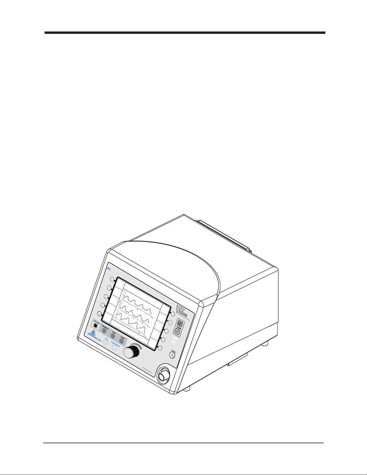
The BiPAP Vision Ventilatory Support System (BiPAP Vision), shown in Figure 1-1, is a microprocessor-controlled, positive pressure ventilatory assist system. The BiPAP Vision incorporates a user interface with multifunction keys, real time graphic displays, and integral patient and system alarms.
The BiPAP Vision features a centrifugal blower to generate airflow, as well as hardware and software platforms
that can be upgraded with an oxygen module and additional patient alarms. The system operates in the Continuous Positive Airway Pressure (CPAP), Pressure Support (S/T), and optional Proportional Assist Ventilation/Timed (PAV/T) modes.
The BiPAP Vision contains a variety of integrated safety and self-diagnostic features. All system functions are
checked at start-up and during operation. Errors are reported by visual and/or audible indicators.
Pressure regulation is achieved by monitoring proximal airway pressure and adjusting flows accordingly to
ensure that the proximal pressure equals the set pressure.
Vision™ Ventilatory Support System Overview
EPAP
6
cm H
O
2
Rate
12
BPM
V
T
1000
IPAP
15
MODE: S/T MONITORING
cm H
O
2
P (cm H
Vol (ml)
Flow (L/min)
ml
MinVent
O)
2
PS = 9
%O
2
cm H
2
O
55
%
14
L/min
PIP
15
cm H
O
2
Options
Figure 1-1
The BiPAP Vision Ventilator
1045049
BiPAP Vision Service Manual
Page 9

Chapter 1: Introduction
1-3
1.2 Service Notice
This service manual was prepared by Respironics primarily for use by qualified technicians
required to service the BiPAP Vision.
1.3 Technical Support
Respironics is committed to customer satisfaction, and may be contacted with any questions or for technical
support at the following numbers:
U.S. and Canada
Phone: 1-800-345-6443
Fax: 1-800-866-0245
International
Phone: 1-724-387-4000
Fax: 1-724-387-5012
Chp. 1
E-Mail service@respironics.com
Visit Respironics Home Page on the World Wide Web at:
http://www.respironics.com
BiPAP Vision Service Manual
1045049
Page 10

Page 11

Chapter 2: Warnings, Cautions, and Notes
Chapter 2: Warnings, Cautions, and
Notes
2.1 Warnings ........................................................................................ 2-2
2.2 Cautions ......................................................................................... 2-3
2. 3 Notes ..............................................................................................2-4
2-1
BiPAP Vision Service Manual
1045049
Page 12

2-2
Chapter 2: Warnings, Cautions, and Notes
Chapter 2: Warnings, Cautions, and Notes
WARNING: Indicates the possibility of injury.
CAUTION: Indicates the possibility of damage to the device.
NOTE: Places emphasis on an operating or procedural characteristic.
2.1 WARNINGS
2.1.1 Safety
• Do not use the BiPAP Vision in the presence of a flammable anesthetic mixture with
air, oxygen, or nitrous oxide.
• Oxygen supports combustion. Do not use oxygen while smoking or in the presence of
an open flame.
• When using the optional oxygen module, the BiPAP Vision does not provide an oxygen
sensor to monitor oxygen concentrations delivered to the patient circuit. Therefore, the
use of oxygen with the BiPAP Vision should be monitored through oximetry.
NOTE: Refer to the Clinical Manual for guidelines on Applications and Operation.
2.1.2 Operational
• If the “Ventilator Inoperable” indicator illuminates, refer to Chapter 6 of this manual for
troubleshooting guidelines.
• Never attach oxygen tubing or any positive pressure source to the pressure port on the
front panel of the BiPAP Vision.
1045049
BiPAP Vision Service Manual
Page 13

Chapter 2: Warnings, Cautions, and Notes
Warnings (Continued)
2.1.3 Service
CAUTION: Electronic components used in this device are subject to damage from static
electricity. Repairs made to this device must be performed only in an antistatic,
ESD-protected environment.
• Do not attempt to make connection to the diagnostic RS232 connector on the back panel of
the BiPAP Vision to obtain repair information while the unit is operating on a patient.
• To assure the safety of the service technician and specified performance of the device,
Respironics recommends that only qualified technicians perform repairs to the BiPAP
Vision. Contact Respironics Technical Service for service training and authorization
information.
• High voltages are present inside this device. To avoid electrical shock, disconnect the
electrical supply before attempting any repairs on the device.
• For continued protection against risk of fire, replace fuses with those of the same type
and rating only.
2-3
2.1.4 Cleaning
• To avoid electrical shock, unplug the BiPAP Vision unit before cleaning it.
2.2 CAUTIONS
• While cleaning the unit, do not allow any liquid to enter the cabinet or the inlet filter.
• Care should be taken to avoid exposing the BiPAP Vision to operating, storage, and
transport temperatures near the extremes specified in Chapter 4. If exposed to such
temperatures, allow the unit to cool or warm to room temperature before turning it on.
• The unit must be positioned on its base for proper operation.
• Always use an inlet filter when the BiPAP Vision is in use.
• If using the oxygen module, do not exceed 100 psig oxygen supply pressure.
BiPAP Vision Service Manual
1045049
Page 14

2-4
Chapter 2: Warnings, Cautions, and Notes
2.3 NOTES
• This device contains a rechargeable nickel-cadmium (NiCAD) battery which is used by
the alarms in the event of a power failure.
• Refer to the BiPAP Vision Clinical Manual for a complete list of operational Warnings,
Cautions, and Notes.
Additional WARNINGS, CAUTIONS, and NOTES are located throughout this manual.
1045049
BiPAP Vision Service Manual
Page 15

Chapter 3: Description and Theory of Operation
Chapter 3: Description and Theory of
Operation
3.1 BiPAP Vision Ventilatory Support System ............................... 3-2
3.2 Power Supply Subsystem (PSS) ................................................ 3-6
3.3 Main Control (MC)...................................................................... 3-8
3.4 Pressure Control (PC) ................................................................. 3-9
3.5 Display Control (DC)................................................................ 3-11
3-1
3.6 Airflow Module (AFM) ............................................................ 3-14
3.7 Oxygen Module (OM) .............................................................. 3-16
3.8 Description of Ventilator Modes ............................................. 3-17
3.9 Nurse Call / Remote Alarm .................................................... 3-19
3.10 Patient Disconnect Alarm ........................................................ 3-21
BiPAP Vision Service Manual
1045049
Page 16

3-2
Chapter 3: Description and Theory of Operation
Chapter 3: Description and Theory of Operation
3.1 BiPAP Vision Ventilatory Support System
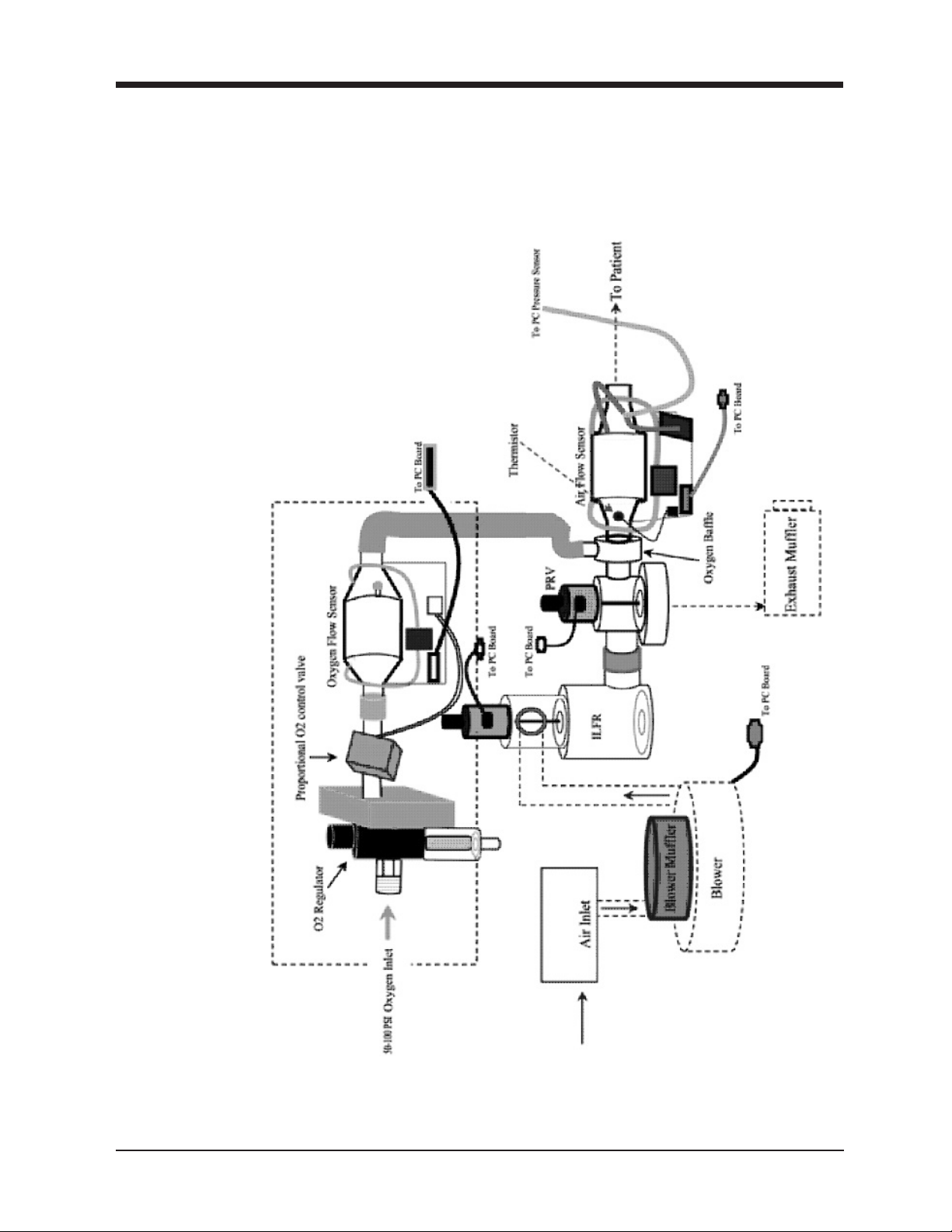
The BiPAP Vision is a microprocessor-controlled, positive pressure ventilatory assist system. The
system’s integral air intake filter draws in ambient air which is then pressurized by the system’s centrifugal blower assembly. The In-Line Flow Restrictor (ILFR) valve and Pressure Regulation Valve (PRV),
which are both located in the blower discharge airway, regulate total flow and pressure at the blower
discharge system. An oxygen module can be installed to add a controlled source of supplemental oxygen,
up to 100%, to the patient.
The Pressure Control (PC) board continuously monitors the readings from the Airflow Module (AFM) of
total gas flow, temperature, generated pressure, and patient circuit pressure to ensure prescribed therapy
to the patient. The PC board transmits process data to the Main Control (MC) board which then provides
overall control of the BiPAP Vision, including conveying instructions to the PC board regarding required
valve stem position and blower speed.
The unique design and operation of the ventilator makes it especially suited for mask applications.
Designed with the BiPAP
conditions, the ventilator is capable of ensuring optimum patient-ventilator synchronicity despite changes
in breathing patterns and circuit leaks. (Refer to the BiPAP Vision Clinical Manual.)
A liquid crystal display (LCD) screen is mounted on the front enclosure of the BiPAP Vision. The LCD
and the Display Control (DC) board provide the primary user interface with the ventilator, including the
visual presentation of data, control features, and visual and audible presentation of alarm conditions. The
user interacts with the ventilator through the touch pad and rotation of the rotary encoder while observing the results of this input on the display. The information provided on the display varies depending on
the state of the ventilator and / or the operations being performed.
The BiPAP Vision incorporates a number of safety features and self-diagnostic systems. System internal
functions are checked automatically at start-up, and periodically throughout normal operation. An
audible and visual alarm announces failures of principal subsystems. Integrated patient alarms are also
provided and are announced on a visual message display area as well as with an audible tone.
The following sections of this chapter describe in more detail the major subsystems and components that
make up the BiPAP Vision and its basic theory of operation.
Auto-Trak Sensitivity
TM
feature that automatically adjusts to changing circuit
1045049
BiPAP Vision Service Manual
Page 17

Chapter 3: Description and Theory of Operation
BiPAP Vision Ventilatory Support System (Continued)
3-3
Subsystem
PSS The Power Supply Subsystem (PSS) provides DC power to the BiPAP Vision
from an AC source.
MC The Main Control (MC) board or Main Control Subsystem (MCS) performs all control,
or data acquisition, and calculations required for the user-selected parameters. In addition,
MCS the MC performs the start-up test and reports all errors.
PC The Pressure Control (PC) board or Pressure Airflow Subsystem (PAS) controls the blower
or and valves to generate and regulate the system pressure. The PAS senses the outlet
PAS pressure and the patient pressure and regulates the outlet pressure to the patient circuit.
DC Through the touch pad, the Display Control (DC) board or Display/Control
or Subsystem (D/CS) evaluates user inputs and passes valid parameters to the MC. The DC
D/CS receives display data from the MC. The DC also has its own internal functions; the
results of which are reported to the MC.
AFM The Airflow Module (AFM), including the mass airflow sensor in the airstream,
provides an airflow measurement interface to the PC, allowing the PC to
measure total flow, temperature, and system pressure.
Function
ILFR The In-Line Flow Restrictor (ILFR) valve assembly regulates the total flow
from the blower discharge.
PRV The Pressure Regulation Valve (PRV) assembly is opened during exhalation to
allow the patient flow to be exhausted.
OM The Oxygen Module (OM) subassembly regulates and proportions the oxygen released
into the air from the blower according to the oxygen concentration level set on the
parameters screen.
BiPAP Vision Service Manual
1045049
Page 18
3-4
*
*
Chapter 3: Description and Theory of Operation
BiPAP Vision Ventilatory Support System (Continued)
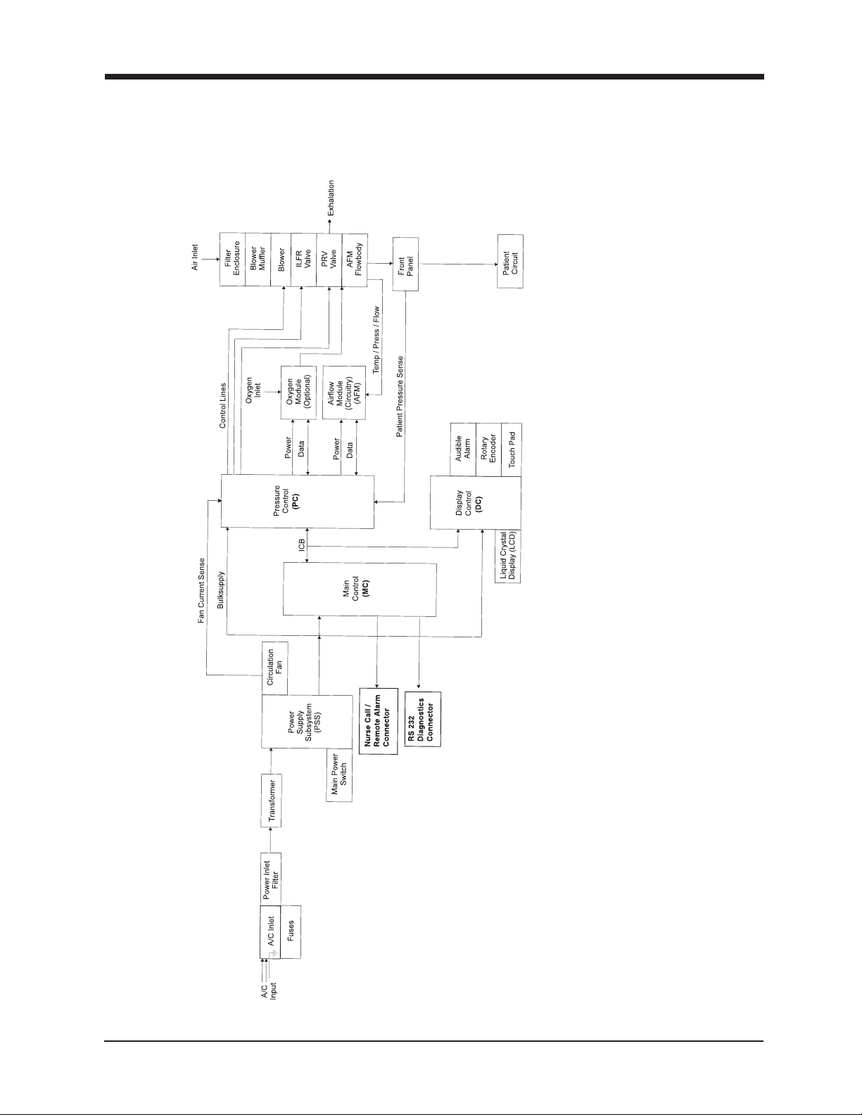
BiPAP Vision Block Diagram
Figure 3-1
BiPAP Vision Block Diagram
*
*
* For S/N 106001 and greater
1045049
BiPAP Vision Service Manual
Page 19
Chapter 3: Description and Theory of Operation
3-5
Pneumatics Block Diagram
BiPAP Vision Service Manual
1045049
Page 20
3-6
Chapter 3: Description and Theory of Operation
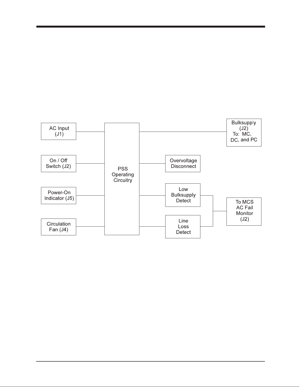
3.2 Power Supply Subsystem (PSS)
The PSS supplies the Main Control (MC), Pressure Control (PC), and the Display Control (DC) with the
proper DC supply voltage. Safety features designed into the circuitry include an overvoltage disconnect,
low voltage supply detect, and line loss detect. Other features include “power-on” indicator voltage,
circulation fan power, and an On/Off switch connection.
1045049
Figure 3-2
PSS Block Diagram
BiPAP Vision Service Manual
Page 21

Chapter 3: Description and Theory of Operation
Power Supply Subsystem (PSS) (Continued)
3.2.1 Input Range
The BiPAP Vision can operate with an AC input of 100, 120, 230, or 240 VAC (±10%) depending on the
model.
3.2.2 DC Supply
The output DC supply is fused at 30 amps and delivers between 20.6 VDC and 35 VDC with a maximum
ripple of 1 vpp (peak-to-peak voltage) to the MC, PC, and DC.
3.2.3 Overvoltage Disconnect
The overvoltage disconnect is used to remove the DC supply output when it exceeds 36 VDC and reconnects it when the level returns to an acceptable value.
3.2.4 AC Fail
The MC module monitors the level of DC supply voltage and the AC voltage output from the transformer
supply winding to determine if an AC fail condition exists.
3-7
Low DC supply detect – If the DC supply voltage drops to 19.38 VDC or lower (nominal), an AC fail
condition will be triggered.
Line loss detect – The AC voltage output from the transformer supply winding is monitored for a loss-ofcycle condition. Both legs of the winding are input to the monitoring circuitry. Whenever AC is lost, the
AC fail signal is activated.
3.2.5 Outputs
The PSS module also includes the following:
a. Front panel “power-on” indicator voltage (J5)
b. Circulation fan power (J4)
c. On / Off switch (part of J2)
d. Circulation fan current sense information to (J12) on the PC subsystem.
BiPAP Vision Service Manual
1045049
Page 22
3-8
Chapter 3: Description and Theory of Operation
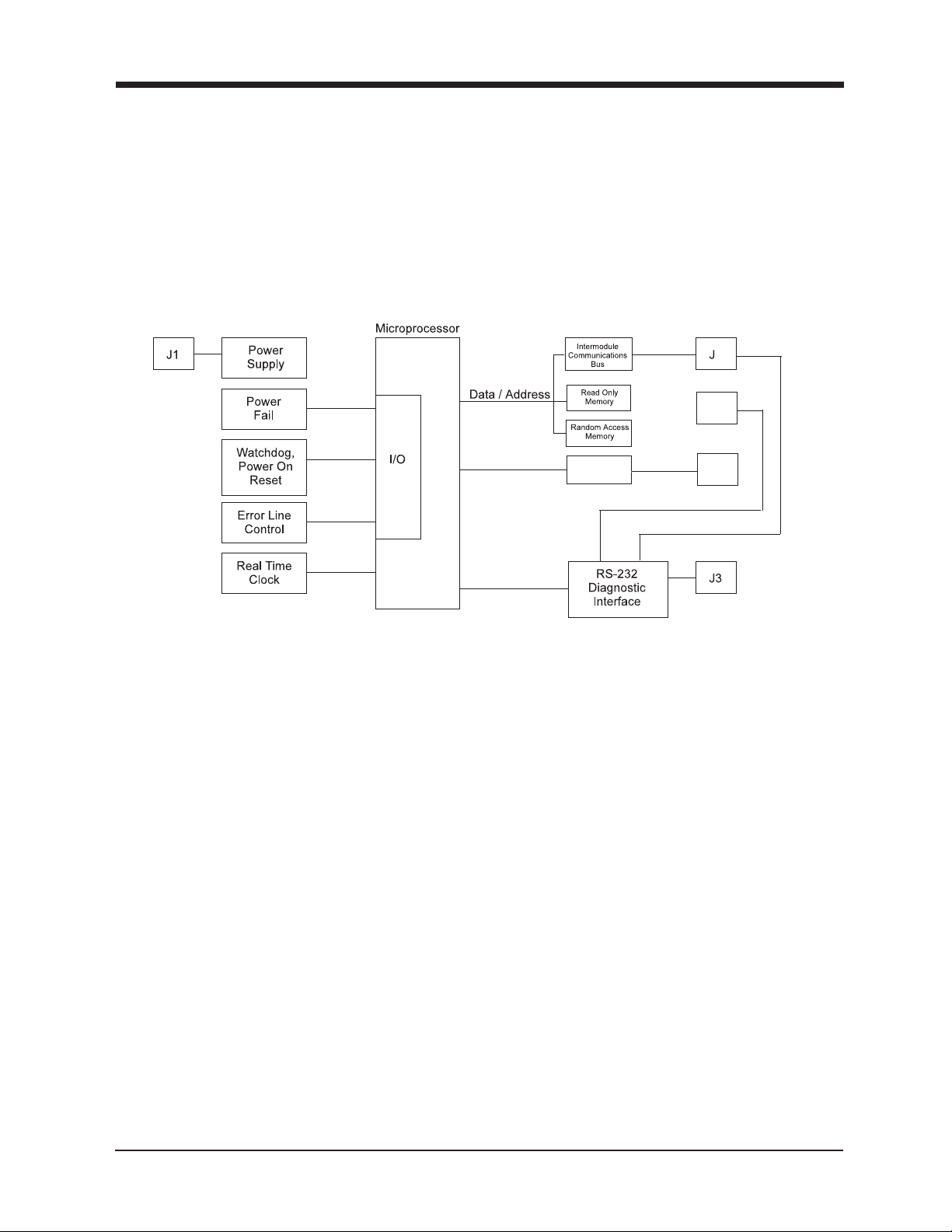
3.3 Main Control Subsystem (MC)
The MC is microcontroller-based and provides overall system control and supervision by monitoring the
activity of all the other system modules and providing commands to these modules based on user and
system input. The MC also acts as the bus controller for all subsystem communications using the
Intermodule Communications Bus (ICB).
4
J6
Nurse Call /
Remote Alarm *
*
DCS RX / TX
J5
PAS RX / TX
1045049
Figure 3-3
MC Block Diagram
* For S/N units >106K
BiPAP Vision Service Manual
Page 23

Chapter 3: Description and Theory of Operation
3.4 Pressure Control Subsystem (PC)
The PC functions through a microcontroller to:
a. Communicate with the Main Controller Subsystem (MC)
b. Communicate to a terminal / PC for diagnostics
c. Acquire sensor data through an Analog-to-Digital Converters (ADC, A / D)
d. Control valves and the blower motor through a Digital-to-Analog Converter (DAC)
e. Respond to or invoke an error signal
3-9
or
J15*
*
* For Units Serial Number <106K
*
*
PC
*
Figure 3-4
PC Block Diagram
BiPAP Vision Service Manual
1045049
Page 24

3-10
Chapter 3: Description and Theory of Operation
Pressure Control Subsystem (PC) (Continued)
3.4.1 Microcontroller Interface
Programmable Array Logic (PAL) memory device decodes the chip selects in such a way that the program code is retrieved from the EEPROM and data is retrieved from the RAM. An additional PAL
provides the interface for the Intermodule Communications Bus (ICB). The microprocessor monitors:
oxygen and gas temperatures; Airflow Module (AFM) and Oxygen Module (OM) detection; In-Line Flow
Restrictor (ILFR), Pressure Regulation Valve (PRV), and oxygen valve DAC control voltage; blower DAC
control voltage; and power supply and reference voltages.
3.4.2 Blower Motor Drive
The complete motor controller includes closed loop speed control via analog circuitry. When the desired
speed and actual speed are known by the processor, the speed is adjusted by increasing or decreasing the
DAC converter output to achieve proper pressure and flow.
3.4.3 Pressure Regulation Valve (PRV) and In-Line Flow Restrictor
(ILFR) Drives
The valve drives have closed loop control via the microprocessor. The microprocessor reads seven
pressure, flow, and temperature sensors through the PC hardware, and receives prescription parameters
from the MC. The microprocessor then adjusts analog DAC voltages to control the PRV and ILFR valves
as required to meet the prescription.
3.4.4 Pressure Sensors
The PC module has two dual pressure sensors (MT1 and MT2) and a single sensor (MT3). They measure
patient pressure, unit outlet pressure, and barometric pressure. These sensors are subject to calibration
with their calculated slope and intercept values stored in the on-board EEPROM. MT3 is a backup outlet
pressure sensor that provides a redundant check of the primary outlet sensor located on the AFM.
NOTE: Calibration is factory programmed and field adjustment is not required.
3.4.5 Error Line Control (ELC) Circuit
The ELC circuit is designed to simply detect a failure from, or signal a failure to, the MC and Display
Control (DC) modules. If the ELC line activates, only a power On / Off of the ventilator can clear this
latched circuit state.
3.4.6 Diagnostics Connector
The diagnostic connector (J3) interfaces with the microprocessor to view PC functions and system errors
on units from serial number 100500 to 105999, unless upgraded. For units greater than this, the diagnostic connector is on the rear of the unit.
1045049
BiPAP Vision Service Manual
Page 25
Chapter 3: Description and Theory of Operation
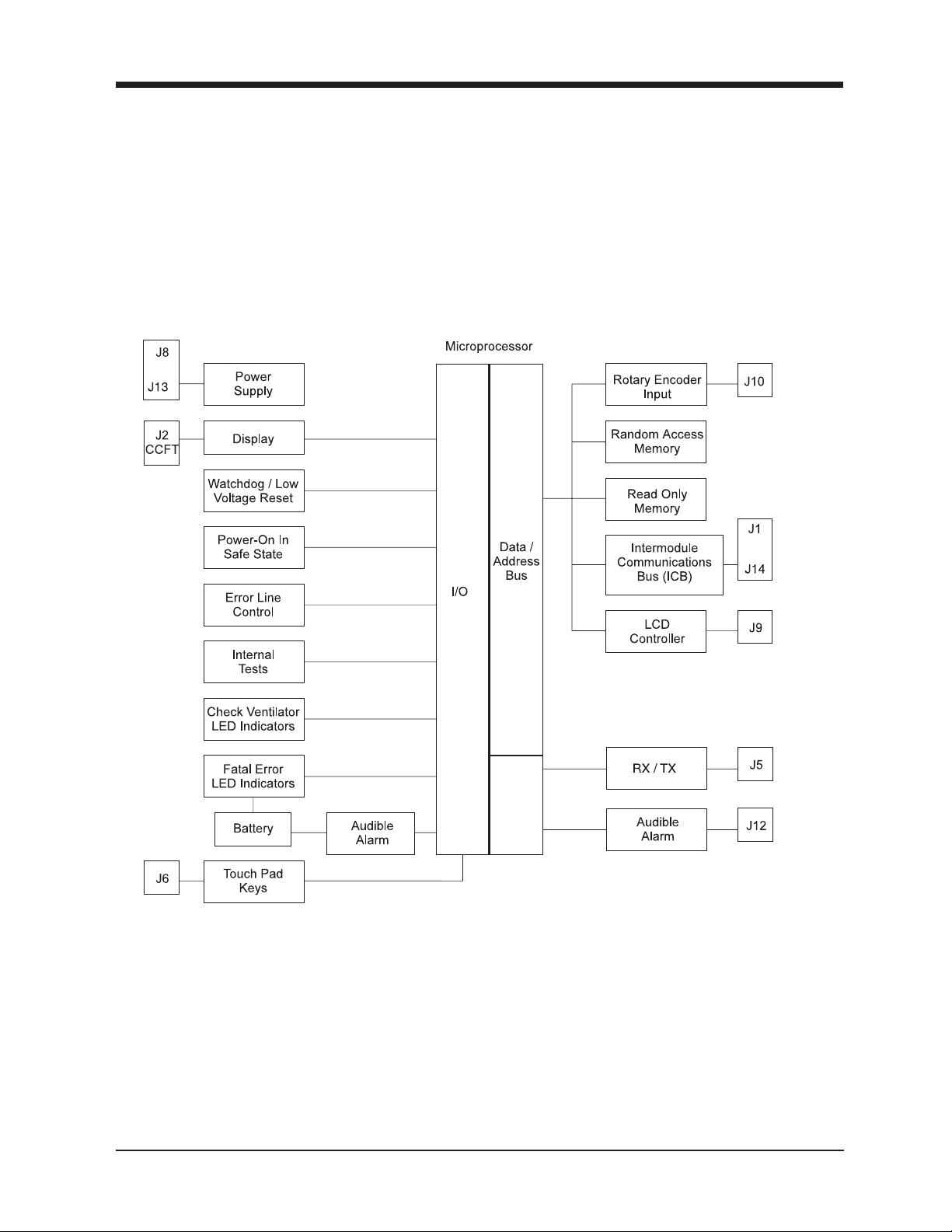
3.5 Display Control Subsystem (DC)
The DC provides a means of displaying the operating mode, measured and calculated operating parameters, parameter setpoints, alarm limits, real-time graphics, and general status information. The DC also
provides the necessary user interface controls to modify the operating mode, parameter set points, alarm
limits, and graphical scales; and to reset or silence the audible alarm, and freeze or unfreeze graphics.
The displays and controls are described in more detail in the following subsections.
*
or
*
3-11
or
*
* For Units Serial Number < 106K
Figure 3-5
DC Block Diagram
BiPAP Vision Service Manual
1045049
Page 26

3-12
Chapter 3: Description and Theory of Operation
Display Control (DC) (Continued)
3.5.1 DC/DC Converter
The DC/DC converter reduces the +24 VDC bulk supply to a +5 VDC logic level. (S/N <106K)
3.5.2 Display Backlight and Contrast Adjustment
A serial 8-bit D/A converter provides two, 0 to +5 VDC which originate in the MCU for these controls.
3.5.3 Display Voltage DC/DC Converter
This adjustable negative voltage converter reduces the level of bulk supply voltage needed to operate the
Liquid Crystal Display (LCD) contrast control.
3.5.4 Cold Cathode Fluorescent Tube (CCFT) Inverter
The DC design has a DC to AC inverter that typically provides 390 VAC to the fluorescent tube in the
display through (J2). The current varies to adjust the brightness of the fluorescent tube.
3.5.5 Reference Voltage Checks
This circuit compares reference voltages to determine if they are at the appropriate level.
3.5.6 Power Failure Alarm Battery Enable
This control detects a power failure from the DC supply.
3.5.7 Alarm Battery Voltage Cutout/Check
The battery voltage cutout /check monitors the battery voltage level and cuts it out if it drops to a level of
approximately 3VDC.
3.5.8 Backup Battery/Charger
The DC contains a 3.6 V nickel cadmium rechargeable battery that operates the audible and visual alarm
indicators for at least 20 minutes, when fully charged, when the Error Line Control (ELC) is active, and
the DC supply has been removed. The battery output is compared to a reference voltage and the battery
is recharged as required through a charging circuit. If necessary, refer to page 5-12 to recharge the
battery.
3.5.9 Check Ventilator Light Emitting Diode (LED) Enable Current
Check
An internal test is performed to verify that the Check Ventilator LED current is acceptable.
3.5.10 Vent Inop LED Current Check
An internal test is performed to verify the Ventilator Inoperative LED current is acceptable.
3.5.11 Error Line Control (ELC) Circuits
The DC contains redundant error signaling circuitry to communicate error conditions among the subsystems. The circuitry’s redundant and diverse nature minimizes the chance of communication failures.
1045049
BiPAP Vision Service Manual
Page 27

Chapter 3: Description and Theory of Operation
Display / Control Subsystem (D / CS) (Continued)
3.5.12 Error LED
The error LED indicates that an error condition was detected, and it illuminates to make unit diagnosis
easier.
3.5.13 Diagnostic Interface
The diagnostic connector interface (J5) interfaces with the MCU to provide a means for the DC to download diagnostic data to a terminal or PC.
3.5.14 EEPROM
A serial EEPROM stores the setpoints for the backlighting and contrast and also for the appropriate
diagnostic data.
3.5.15 LCD Controller
The DC circuit contains an LCD controller that interfaces with the display.
3-13
3.5.16 Debouncing / Keypad Matrix
The matrix keys are debounced and then the microprocessor scans the matrix to determine what key was
depressed.
3.5.17 Rotary Encoder Control
The rotary encoder control circuit detects relative position, direction, and speed of the rotary encoder, all
within one detent of movement.
3.5.18 Audible Alarm Activation
The audible alarm is activated by either an input from the ELC, the power fail circuitry, or the test alarm
signal from the MCU. It will also occur when the wrong key has been depressed, an adjustable parameter
has reached its limit, or the error signal has been activated.
3.5.19 Audible Alarm Current Check
An internal test is performed to verify the audible alarm current is acceptable.
3.5.20 “Power-on“ in Safe State
The DC contains circuitry that causes the hardware to “power-on” in a safe state; which is when the
backlight is off, the display is off, and the Intermodule Communications Bus (ICB) is terminated. When
the MCU determines that no Vent Inop error exists, it lets the unit resume operation under normal
operating conditions.
3.5.21 Watchdog and Low Voltage Reset
The watchdog function has to be periodically reset by the microprocessor if a time-out period has been
exceeded. This function is designed to reset the processor if the software gets lost. When a low logic level
is detected, the ELC will be activated resulting in a system shutdown.
BiPAP Vision Service Manual
1045049
Page 28
3-14
Chapter 3: Description and Theory of Operation
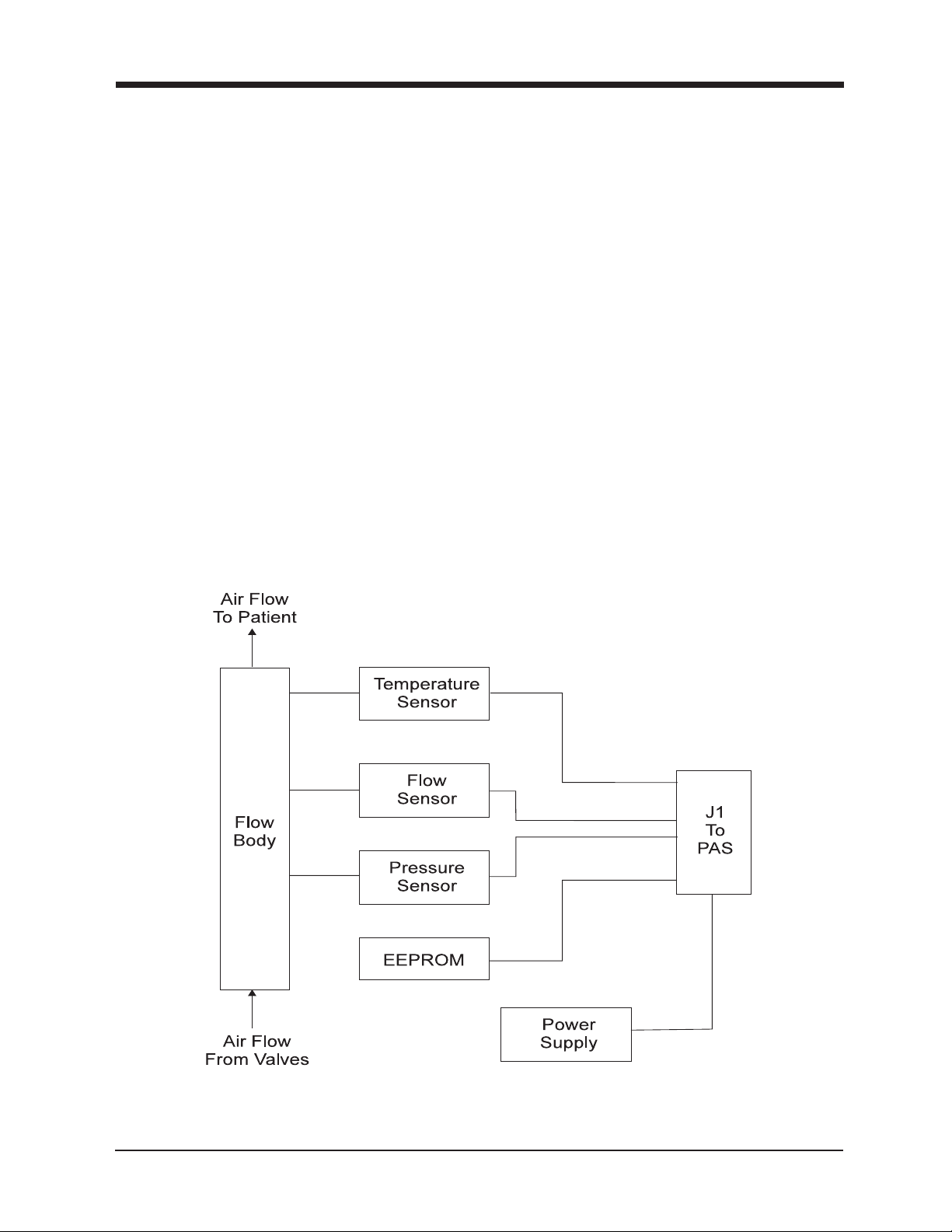
3.6 Airflow Module (AFM)
The AFM is a submodule of the Pressure Control (PC). The AFM receives power from the PC and provides the following analog signals to the PAS:
a. Gas flow indication
b. Pressure indication
c. Temperature indication
To provide indications accurate enough for system requirements, the AFM must be calibrated. Calibration data is stored in a nonvolatile memory that is part of the AFM. The flow, pressure, and temperature
indications are for the ventilator gas stream flowing through a “flow body” attached to the AFM circuit
board.
3.6.1 Flow Body
The flow body, with laminar flow element, is added to the ventilator gas stream, creating a small pressure
differential to short a fraction of the flow through the AFM sensor. Inlet, outlet, and pressure ports are
part of the flow body for tubing attachment to the AFM electronic sensors. Also, a hole is molded into the
flow body to position the temperature sensor. The body has molded feet for attaching it to the AFM
circuit board assembly.
1045049
And/Or Oxygen Supply
Figure 3-6
AFM Block Diagram
BiPAP Vision Service Manual
Page 29

Chapter 3: Description and Theory of Operation
Airflow Module (AFM) (Continued)
3.6.2 Analog Reference
The PC provides the AFM with power in the form of +12 VDC, –12 VDC, analog ground, +5 VDC, and
digital ground. An analog voltage reference supply is derived from the +12 VDC to power the pressure
and flow sensors so their bridge outputs can be factory calibrated.
3.6.3 Flow Indication
Total gas flow indication is provided by MT1. It is then amplified by an instrumentation amplifier, lowpass filtered, and sent to the PC board for conversion.
3.6.4 Pressure Indication
MT2, a precision compensated pressure sensor, provides unit outlet pressure indication. The sensor is
followed by a low-pass filter and a differential amplifier, and then sent to the PC board for conversion.
3.6.5 Temperature Measurement
The temperature is measured using a sensor inserted into a molded hole in the flow body. The BiPAP
Vision requires temperature indication to correct air density and detect an undesirable temperature rise in
the patient circuit.
3-15
3.6.6 Calibration
A data acquisition system, operating on a personal computer, is the control platform for AFM calibration
of temperature, pressure, and flow. Correction factors are derived and stored in the AFM module in an
EEPROM, with calibration accomplished by balancing the flow transducer bridge with an EEPOT. The
PAS uses temperature, pressure, and flow to correct for actual operating conditions. Once calibrated, the
AFM is interchangeable with other AFM assemblies.
NOTE: Calibration is factory programmed only.
3.6.7 Module Detection
The PC must know the AFM is connected, since it is required for normal operation of the ventilator. An
extra line pulls a PC microcontroller line near zero volts. If the line is above two volts, the AFM is not
connected, and the PC will transition to the error state.
BiPAP Vision Service Manual
1045049
Page 30

3-16
Chapter 3: Description and Theory of Operation
3.7 Oxygen Module (OM)
The OM is an optional submodule of the Pressure Control (PC). It receives power from the PC and
provides an analog signal to the PC for oxygen flow indication. To provide indications accurate enough
for system requirements, the OM must be calibrated. Calibration data is stored in a nonvolatile memory
that is part of the OM. The flow indication is for the ventilator pure oxygen stream flowing through a flow
body attached to the OM circuit board.
Figure 3-7
OM Block Diagram
PC
1045049
BiPAP Vision Service Manual
Page 31

Chapter 3: Description and Theory of Operation
3.8 Description of Ventilator Modes
The BiPAP Vision comes standard with two operating modes: Continuous Positive Airway Pressure
(CPAP) and Spontaneous/Timed (S/T). A third, optional, Proportional Assist Ventilation/Timed (PAV/
T) is also available.
3.8.1 Continuous Positive Airway Pressure (CPAP)
CPAP provides a constant pressure level delivered over the complete range of the patient’s spontaneous
breathing cycle. Pressure is controlled and maintained. Flow is available to meet changing patient
demands and automatically compensate for leaks. The mode delivers the prescribed level of pressure
that has been set with the CPAP control (Range: 4 to 20 cm H2O).
3.8.2 Spontaneous/Timed (S/T)
The S/T mode provides either pressure support during spontaneous breaths or time-triggered, pressurelimited, time-cycled machine breaths.
3-17
Spontaneous Breaths
Two pressure levels are set: an EPAP level (range 4 to 20 cm H2O) to establish a baseline pressure and an
IPAP level (range 4 to 40 cm H2O) that determines the amount of pressure support delivered with each
breath (PS = IPAP– EPAP). During the inspiratory phase, the BiPAP Vision responds as necessary to
satisfy the patient’s flow requirements while maintaining the preset IPAP pressure. Under these conditions, the patient is active in determining inspiratory time and tidal volume. The delivered tidal volume
will be dependent upon the pressure differential between the IPAP and EPAP levels, patient effort, and
the combined resistance and compliance of the circuit and the patient. If the patient does not actively
participate, the BiPAP Vision responds appropriately.
Timed Breaths
The S/T mode can also provide a time-triggered, pressure-limited, time-cycled machine breath, when the
spontaneous respiratory rate drops below the Rate control setting. If the ventilator does not detect a
spontaneous trigger within the interval determined by the Rate control setting, it will activate a timetriggered machine breath and deliver the IPAP level. Machine breaths are not synchronized with patient
effort, and once triggered to IPAP, the balance of the cycle is determined by the Timed Insp. Control
setting. A maximum Timed Inspiratory setting of 3.0 seconds can be set, as long as the I:E Ratio does not
exceed 1:1, as determined by the Rate setting. For example, see Figure 3-12. If the Rate control is set at 10
BPM, the total respiratory cycle is six seconds. If a spontaneous trigger occurs before the six-second cycle
time has elapsed, a spontaneously-triggered, pressure support breath occurs, a timed trigger will not
occur, and the timer is reset for a new six second interval. If a six second interval passes without a
spontaneous trigger, a timed trigger will be initiated and IPAP will be delivered for the duration of time
set by the Timed Inspiration setting.
BiPAP Vision Service Manual
1045049
Page 32

3-18
Chapter 3: Description and Theory of Operation
Description of Ventilator Modes (Continued)
Figure 3-12
Timed Breath Example
3.8.3 Proportional Assist Ventilation / Timed Mode (PAV/T)
For a detailed description of functioning of the Proportional Assist Ventilation/Timed (PAV/T) Mode,
refer to the appropriate BiPAP Vision Clinical manual. This mode utilizes the design features of S/T
mode and is a software enhancement only.
1045049
BiPAP Vision Service Manual
Page 33

Chapter 3: Description and Theory of Operation
3.9 Nurse Call/Remote Alarm Feature Operation (for s/n units
greater than 106000 only)
The unit will activate a remote signal for system shutdowns, patient alarms, and Loss of AC Power conditions which inhibit therapy. Note that a Check Vent condition does not activate the nurse call signal. The
nurse call signal can be silenced via the Alarm Silence key for the same amount of time that the audible
alarm on the Vision is silenced (two minutes). The signal can also be cleared by selection of the Alarm
Reset key. The nurse call signal will automatically terminate when a patient alarm self-cancels.
The Nurse Call/Remote Alarm feature is meant to be a backup with the main Vision alarm system being
the primary alarm/alert mechanism.
The Nurse Call or Remote Alarm signal is generated on the MC board and then can be connected to a
hospital nursing station. This signal is opto-isolated and used to switch a relay to provide open or closed
contacts to the remote station circuit. The arrangement of the two jumpers (JP1 and JP2) on the MC determine the output configuration that is utilized by a common connector on the rear panel of the Vision.
3-19
The Nurse Call Adapter (RI P/N 1014280) along with the Nurse Call Cable (RI P/N 1003742) can be used
to connect the Vision to a Nurse Call station.
The jumper configuration on the MC circuit board can be selected to meet requirements according to the
following table. Refer to the photo for jumper location.
Option JP1 JP2 No Alarm Output Alarm Option System Requiring
1 2,3 2,3 51.1K Open Respironics Remote Alarm
2 2,3 1,2 Closed Open Central Alarm System
3 1,2 1,2 Open Closed Central Alarm System
NOTE: Option 2 is the original factory set configuration for S/N 106001 to 106368.
Option 3 is the original factory set configuration for S/N 106369 and greater.
JP 2
BiPAP Vision Service Manual
JP1
1045049
Page 34

3-20
Chapter 3: Description and Theory of Operation
Nurse Call / Remote Alarm (Continued)
Details of option selections:
Option 1:
For use with Respironics Remote Alarm ( RI p/n 34003, or equivalent).
Option 2:
For use with alarm systems requiring NORMALLY OPEN contacts for an “alarm” condition and CLOSED contacts
for a “no alarm” condition.
Option 3:
For use with alarm systems requiring NORMALLY CLOSED contacts for an “alarm” condition and OPEN contacts
for a “no alarm” condition.
Caution: The Vision Nurse Call/Remote Alarm port shall be connected to nurse call systems that meet the relevant
local safety standards. Secondly, the nurse call port shall be connected to a low voltage circuit (less or
equal to 42.4V peak ac or 50V dc). The leakage currents from the low voltage circuit shall not cause the
Vision leakage currents to exceed acceptable levels. Lastly, the rated output current of the low voltage
circuit shall not exceed 1A.
1045049
BiPAP Vision Service Manual
Page 35

Chapter 3: Description and Theory of Operation
3.10 BiPAP Vision Patient Disconnect Alarm Description of
Operation
The patient disconnect alarm (“Disconnect”) is based on the flow limit control algorithm in the Vision. The mitigation for the Disconnect alarm is to put the unit into flow limit control. This same action is done when the user selects
the Standby key.
3.10.1 Detection
The unit determines that a patient is not connected to the circuit anymore based on flow for the given pressure. This
is implemented via a look-up table, with a flow entry for every generated pressure. The range of flows is 95 to 180
LPM, with 180 LPM being the low limit for any pressure above 9 cmH2O. If the unit detects flow greater than the
threshold at any given pressure for more than 10 seconds (3 seconds in for software earlier than 13.2), the unit puts
itself into the Flow Limit Control state. In this state, the unit attempts to limit the flow coming out of the mask in
order to make putting the mask back on the patient easier and more comfortable for the patient.
3-21
Also, for safety concerns, the oxygen valve closes to discontinue oxygen delivery during this condition.
When the Standby key is selected by the user, the unit automatically enters the FLC state, regardless of the flow at
the time the Standby key is selected.
In order to limit the flow, the unit drops the pressure to 4 cmH2O. The algorithm was enhanced to work with the Full
Face Mask a while ago. The Full Face Mask has a flap that will close the patient circuit and open the mask to
atmosphere upon loss of flow and pressure. This flap must be kept in a position during FLC so that the patient
circuit is not occluded. This allows the unit to detect when the patient is reconnected. The enhancement to the
algorithm consists of the pressure being slowly increased to keep the flow at 160-170 LPM. The pressure level is
limited to 10 cmH2O for software 11.2 and 11.3 (15 cmH2O for software 11.3a and higher), regardless of how much
flow is being generated. Therefore, the unit will either output 160-170 LPM at some pressure or will be limited to
some lesser flow at 10 cmH2O for software 11.2 and 11.3 (15 cmH2O for software 11.3a and higher).
3.10.2 Termination
There are two termination stages to FLC. During the first stage, as the pressure is being increased from 4 cmH2O to
its maximum of 10 cmH2O for software 11.2 and 11.3 (15 cmH2O for software 11.3a and higher), FLC will be
automatically terminated if the unit detects negative flow (i.e., the patient breaths back into the unit). This pressure
increase takes about 10 – 12 seconds for software versions earlier than 13.2, depending on how soon the flow set
point is reached. There have been two enhancements in software version 13.2 in this area. The first is that the
pressure is increased faster (1 cmH2O per 40 ms instead of the previous ¼ cmH2O per 40 ms) to shorten the amount
of time in stage one. The second change concerns the flow range processing. In software versions earlier than 13.2,
when the pressure is dropped to 4 cmH2O and the flow is greater than the desired flow range (160-170 LPM), the
flow limit algorithm attempts to decrement the pressure to get the flow into that desired range. In software version
13.2, that was changed to immediately enter stage 2 under that condition.
BiPAP Vision Service Manual
1045049
Page 36

3-22
Chapter 3: Description and Theory of Operation
Once either the flow set point or the maximum pressure is reached, the unit will automatically terminate
FLC for either the detection of negative flow or if flow varies from the current flow by more than 40 LPM
in software versions prior to 13.2 and 20 LPM for software version 13.2. For instance, if the 160-170 LPM
set point has been reached, the unit will terminate FLC if the flow drops below 120 LPM or goes above
210 LPM in older software and 140-190 LPM in the new software.
If the flow set point has not been reached, the current flow at 10 cmH2O for software 11.3 and 11.3 (15
cmH2O for software 11.3a and higher) is used as the set point. For instance, if only 80 LPM can be
reached at 10 cmH2O for software 11.3 and 11.3 (15 cmH2O for software 11.3a and higher), the thresholds
for automatic termination of FLC will be 40 LPM and 120 LPM in older software and 60-100 LPM in new
software.
This allows FLC to be terminated without the patient necessarily breathing back into the machine but by
the simple act of refitting the mask to the patient.
The Standby condition, besides being terminated automatically by the above methods, can also be
manually terminated by reselecting the highlighted Standby soft key on the Monitoring screen.
When FLC is terminated during a “Disconnect” alarm period, the alarm is self-cancelled. That means
that the audible component of the alarm is silenced but the visual component of the alarm remains
displayed on the screen. That can be cleared by selecting the Alarm Reset key.
Note: During FLC, the oxygen parameter setting reduces to 21%, regardless of the setting.
1045049
BiPAP Vision Service Manual
Page 37

Chapter 4: Specifications and Control Ranges
Chapter 4: Specifications and
Control Ranges
4.1 Specifications ...............................................................................4-2
4.2 Control Ranges and Increments .............................................. 4-5
4-1
BiPAP Vision Service Manual
1045049
Page 38

4-2
Chapter 4: Specifications and Control Ranges
Chapter 4: Specifications and Control Ranges
4.1 Specifications
ENVIRONMENTAL:
Temperature ....................................... Operating: 40° F to 104° F (4.4° C to 40° C)
Transport / Storage: –4° F to 140°F (–20o C to 60o C)
Humidity ............................................ Storage and Operating: 0 to 95% Relative Humidity
PHYSICAL:
Dimensions ........................................ At the base: 16" (L) × 14 3/8" (W) × 10 5/8" (H)
(40.6 cm x 36.5 cm x 27cm)
Weight ................................................ 34 lbs (15.4 kg)
ELECTRICAL:
AC Input Voltage (VAC) ................. 100/120/230/ 240 VAC
Single Phase
±10%
Fuses ................................................... 100 – 120 VAC ~ T 3.5 A, 5 × 20 mm, Time Lag (×2)
(For serial no.’s 100500 and higher –
Respironics Reorder # 1000749)
115 VAC ~ T 3.0 A, 250 V, ¼” × 1¼”
(For serial no.’s 100499 and lower –
Respironics Recorder # 582100)
220 VAC, 230 VAC and 240 VAC ~ T 1.6 A, 250 V, 5 × 20 mm
(For all serial no.’s – Respironics Recorder # 1000750)
Power Consumption ........................ 300 VA max.
AC Current ........................................ 3.0 A maximum
AC Frequency .................................... 50/60 Hz
Class ................................................... Protection Against Electrical Shock: Class I
1045049
BiPAP Vision Service Manual
Page 39

Chapter 4: Specifications and Control Ranges
Specifications (Continued)
Type .................................................... BF
Degree of Protection Against Harmful Ingress of Water:
Ordinary Equipment, IPX0
Electromagnetic
Compatibility ..................................... The BiPAP Vision meets the requirements of IEC 601-1-2
Earth Resistance ................................ Less than 0.10 ohms
Earth Leakage Current ......................
Normal Pole, No Earth, L2 ........ Less than 300 µA
Reverse Pole, No Earth, L2 ........ Less than 300 µA
Reverse Pole, No Earth, No L2.. Less than 1000 µA
Normal Pole, No Earth, No L2 .. Less than 1000 µA
Insulation Resistance ........................ Greater than 2 megaohms
Noise Level ......................................... No specification is given because various test instruments, test
procedures, and unit operating conditions produce varying
results.
4-3
Alarm Sound Level ........................... Between 70 and 85 dBA peak at a distance of 1 meter.
PRESSURE:
Output ................................................. 4 to 40 cm H2O
Dynamic Regulation.......................... ± 2 cm H2O at sinusoidal flow @ ± 100 L/min
Static Regulation ................................ ± 2 cm H2O from –60 to 120 L/min
Elevation.............................................. 0 to 5000 ft above sea level
CONTROL ACCURACY:
Timed Inspiration.............................. ± 0.2 sec of the set point
Rate ...................................................... ± 1 BPM of the set point
Oxygen Concentration ....................... The greater of ± 3% or ±10% of the set point
DISPLAY ACCURACY:
Pressure ............................................... ± 1 cm H2O
Volume ................................................ ± 10% (during stable conditions)
Flow ..................................................... ± 10% (during stable conditions)
BiPAP Vision Service Manual
1045049
Page 40

4-4
Chapter 4: Specifications and Control Ranges
Specifications (Continued)
TRIGGER SENSITIVITY:
(Refer to BiPAP Vision Clinical Manual Auto-Trak section for more details)
Spontaneous Trigger ......................... Shape Trigger
Volume 6 cc above
Spontaneous Cycle ............................ Spontaneous Expiratory Threshold (SET)
Shape Cycle
IPAP maximum of 3.0 sec
Flow Reversal
OXYGEN MODULE INLET:
Pressure Range .................................. 50 to 100 psig
Inlet Fitting ......................................... DISS male oxygen connector
INTERNAL BATTERIES:
Alarm Battery ..................................... NiCAD
Location: D/C
3.6 VDC, 110 mAh
Rechargeable (See Section 5.9.3 for details)
(RI P/N 1012819)
V
leak
Data Retention Battery Type: Lithium Cell
(for original MCS board)
Data Retention Battery Type: Lithium Cell
(for current MC Board ) Location: MCS
Location: MCS
+3 VDC, 300 mAh
Not Rechargeable
(RI P/N 1001988)
+3 VDC, 300 mAh
Not Rechargeable
(RI P/N 1006005)
1045049
BiPAP Vision Service Manual
Page 41

Chapter 4: Specifications and Control Ranges
4.2 Control Ranges and Increments
NOTE: Refer to the applicable BiPAP Vision Clinical Manual for PAV/T information.
4.2.1 Parameters
4-5
*With optional Oxygen Module
4.2.2 Alarms (Adjustable)
Alarm Control Control
High Pressure 5 to 50 cm H201 cm H
Low Pressure Disabled to 40 cm H20 1 cm H20
Low Pressure Delay 0 to 60 sec. 1 cm H20
Apnea Disabled; 20 to 40 sec. 4 set points;
Low Minute Disabled to 99 L/min. 1 L/min.
Ventilation*
High Rate* 4 to 120 BPM 1 BPM
Low Rate* 4 to 120 BPM 1 BPM
*With optional Alarm Module
Range Increments
0
2
Disabled, 20, 30, 40 sec.
BiPAP Vision Service Manual
1045049
Page 42

4-6
Chapter 4: Specifications and Control Ranges
Control Ranges and Increments (Continued)
4.2.3 Display Ranges & Increments
PARAMETER DISPLAY DISPLAY
RANGE RESOLUTION
IPAP 0 TO 50 CM H
EPAP 0 TO 50 CM H
CPAP 0 TO 50 CM H
O 1 CM H
2
O 1 CM H
2
O 1 CM H
2
2
2
2
RATE 0 TO 150 BPM 1 BPM
EXHALED TIDAL 0 TO 4000 ML 1 ML
VOLUME (VT)
MINUTE VENTILATION 0 TO 99 L /MIN 1 L / MIN
(MIN VENT)
TOTAL LEAK (TOT LEAK)0 TO 300 L/MIN 1 L / MIN
PATIENT LEAK 0 TO 300 L /MIN 1 L /MIN
(PT. LEAK)
O
O
O
1045049
PEAK INSPIRATORY 0 TO 50 CM H
O 1 CM H
2
PRESSURE (PIP)
PERCENT OF PATIENT 0 TO 100% 1%
TRIGGERED B REATHS
(PT.TRIG)
TI/TTOT 0 TO 100% 1%
BiPAP Vision Service Manual
O
2
Page 43

Chapter 5: Routine Maintenance
Chapter 5: Routine Maintenance
5.1 Cleaning the BiPAP Vision ....................................................... 5-2
5.2 Replacing the Inlet Filter........................................................... 5-3
5.3 Cleaning / Replacing the Nylon Mesh Inlet Filter ..............5-4
5.4 Replacing the Oxygen Regulator Filter ................................. 5-6
5.5 Changing the System Fuses...................................................... 5-8
5.6 Voltage Selection.......................................................................5-10
5.7 Power Cord Inspection ............................................................5-10
5-1
5.8 Internal Alarm Battery ............................................................ 5-11
5.9 Preventive Maintenance Schedule ........................................5-14
BiPAP Vision Service Manual
1045049
Page 44

5-2
Chapter 5: Routine Maintenance
5. 1 Cleaning the BiPAP
CAUTION: Do not immerse the BiPAP Vision in water or allow any liquid to enter the cabinet or
the inlet filter.
NOTE: The following guidelines for cleaning refer to the BiPAP Vision only. Refer to the
individual instructions for cleaning accessories.
Vision
5.1.1 Cleaning the Front Panel
Clean the front panel as needed by wiping with water or 70% isopropyl alcohol only.
5.1.2 Cleaning the Enclosure
Clean the exterior of the enclosure as needed by wiping with any anti-bacterial agent.
CAUTION: Do not allow any liquid to enter the cabinet or the inlet filter.
NOTE: Do not clean the Auto-Trak sticker with anything except mild soap and water.
1045049
BiPAP Vision Service Manual
Page 45

Chapter 5: Routine Maintenance
5.2 Replacing the Inlet Filter
CAUTION: A dirty inlet filter may cause high operating temperatures, and may affect ventilator
performance. Examine the inlet filter for integrity and cleanliness before each use, and
as required during operation.
Step 1 Turn the BiPAP Vision OFF and unplug the electrical cord from the wall outlet and from the
back of the unit.
Removing the Filter
Step 2 Remove the inlet filter cap by pinching the latch, then rotate the cap until the hinge is
free from its slot.
NOTE: The inlet filter is disposable. Do not attempt to clean the inlet filter. When the filter is
dirty replace it with a new filter. Use only Respironics filters; see Chapter 7 for
the filter reorder number.
5-3
(P/N 582101 x6)
Figure 5-1
Removing the Filter Cap
(P/N 1003444)
Installing the Filter
Step 3 Place the filter inside the cap, then reverse Step 2 to reinstall the filter cap.
NOTE: To clean any of the accessories, refer to each accessory’s instruction sheet.
BiPAP Vision Service Manual
1045049
Page 46

5-4
Chapter 5: Routine Maintenance
5. 3 Cleaning/Replacing the Nylon Mesh Inlet Filter
CAUTION: A dirty nylon mesh inlet filter may cause high operating temperatures
and may affect ventilator performance.
Step 1 Turn the BiPAP Vision off and unplug the electrical cord from the wall outlet and
from the back of the unit.
Step 2 Remove the filter cap and inlet filter. (See Section 5.2 for more detailed instructions on
removing the filter cap and inlet filter.)
Step 3 Using a medium Phillips screwdriver, remove the two screws that secure the nylon mesh
inlet filter to the filter enclosure. Remove the nylon mesh inlet filter.
Figure 5-2
Removing the Nylon Mesh Filter
NOTE: Depending on the condition of the nylon mesh inlet filter, it may be cleaned and
reused. If the filter is in good shape, follow the cleaning instructions in Step 4. If the
filter must be replaced, proceed to Step 5.
NOTE: If the nylon mesh inlet filter is to be cleaned, care should be taken to protect the
adhesive on the edges of the filter. If the adhesive is damaged, the filter may not
correctly seal when reinstalled.
1045049
BiPAP Vision Service Manual
Page 47

Chapter 5: Routine Maintenance
Cleaning / Replacing the Nylon Mesh Inlet Filter (Continued)
Step 4 Using a solution of mild soap and water, carefully clean then thoroughly rinse the nylon
mesh inlet filter. Insure that the filter is completely dry before reinstalling it in the unit.
Step 5 If necessary, remove the protective backing from the nylon mesh inlet filter. Align the new
cleaned nylon mesh inlet filter with the filter enclosure. Press the edges of the filter firmly in
place. Secure the filter to the filter enclosure using the two Phillips screws.
5-5
BiPAP Vision Service Manual
1045049
Page 48

5-6
Chapter 5: Routine Maintenance
5.4 Replacing the Oxygen Regulator Filter
CAUTION: A dirty Oxygen Regulator filter may reduce system performance. Examine the filter
for integrity and cleanliness before each use.
NOTE: Replace the filter as necessary to ensure normal operation.
Step 1 Position the BiPAP Vision so that the back is easily accessible.
Step 2 Disconnect the Oxygen Module (OM) input line.
Step 3 Firmly grasp the plastic body of the regulator bowl and rotate it counterclockwise to
remove it. (Direction is referenced from the bottom of the unit.)
NOTE: The regulator bowl has a standard right-hand thread.
(shown is for original Oxygen Module)
Step 4 Remove the original filter.
Figure 5-3
Removing the OM Regulator Bowl
1045049
BiPAP Vision Service Manual
Page 49

Chapter 5: Routine Maintenance
Replacing the Oxygen Regulator Filter (Continued)
(shown is for original Oxygen Module)
5-7
Figure 5-4
Removing the OM Filter
Step 5 Insert the new filter.
Step 6 If necessary, clean the regulator bowl with mild soap and water and dry completely.
Step 7 Put the regulator bowl in place and rotate it clockwise until securely tightened.
Step 8 Connect the oxygen input line to the OM.
BiPAP Vision Oxygen Module Regulator Filter and Regulator Bowl Compatibility
Note: Refer to the information below for compatibility when ordering Oxygen bowl and filter
replacements.
Oxygen Module (OM) Manifold / Regulator Bowl For Oxygen Module S/N < 300000, use part
number 582154
For Oxygen Module S/N > 299999, use part
number 1007546*
Oxygen Module (OM) Manifold / Regulator Bowl filter (x5)
For Oxygen Module S/N < 300000, use part
number 582153
For Oxygen Module S/N > 299999, use part
number 1007547*
* This part is also for the Oxygen Modules that do not have a serial number on the Oxygen Module cover.
BiPAP Vision Service Manual
1045049
Page 50

5-8
Chapter 5: Routine Maintenance
5.5 Changing the System Fuses
WARNING: Unplug the BiPAP Vision before changing the fuses.
NOTE: This procedure applies to Vision S/N’s 100500 and greater.
Step 1 Unplug the AC power cord from the wall outlet and from the power entry module on the
rear of the BiPAP Vision.
Step 2 With a small, flat-blade screwdriver, gently pry open the fuse holder door from the top. The
door hinges downward.
Figure 5-5
Opening the Fuse Door
Step 3 Pry the fuse drawers loose and slide them out of the power entry module.
Step 4 Pull the fuses out of the fuse drawers.
1045049
BiPAP Vision Service Manual
Page 51

Chapter 5: Routine Maintenance
Changing the System Fuses / Operating Voltage Selection (Continued)
5-9
Figure 5-6
Replacing the Fuses
Step 5 Replace both fuses.
Step 6 Place the new fuses in the fuse drawers and slide the fuse drawers back into the power entry
module with the arrows on the front of the drawers pointing to the right.
Step 7 Select the proper operating voltage by removing the drum and reinserting it with the
desired voltage displayed.
NOTE: Use only Respironics approved fuses. See Section 5.6 for fuse part numbers.
Step 8 Swing the fuse drawer door shut and snap it into place.
Step 9 Plug the AC power cord into the BiPAP Vision and the wall outlet.
BiPAP Vision Service Manual
1045049
Page 52

5-10
Chapter 5: Routine Maintenance
5.6 Voltage and Fuse Selection
The voltage selection is originally set at the factory. If you wish to use the BiPAP Vision with a different
operating voltage, refer to Section 5.5.
NOTE 1: Vision S / N’s 100500 and greater:
• For operating voltages of 100 and 120 VAC, use RI P/N 1000749 fuses.
• For operating voltages of 230 and 240 VAC, use RI P/N 1000750 fuses.
NOTE 2: Visions S / N’s 100499 and less:
• For operating voltage of 115 VAC, use RI P/N 582100 fuses.
• For operating voltage of 220 and 240 VAC, use RI P/N 1000750 fuses.
5.7 Power Cord Inspection
Inspect the power cord and replace if damaged or shows signs of wear.
1045049
BiPAP Vision Service Manual
Page 53

Chapter 5: Routine Maintenance
5.8 Internal Alarm Battery
5.8.1 Battery Function
The BiPAP Vision contains an internal NiCAD battery located on the DC (P/N 1012819) to activate the
Ventilator Inoperative visual and audible alarm indicators if an error occurs. A fully charged battery can
maintain the audible alarm for up to 20 minutes.
5.8.2 Low Battery Condition
The NiCAD battery can lose its charge if the BiPAP Vision is not used for an extended time. In a typical
environment, a fully charged battery can be stored approximately six months before losing its charge, but
the discharge rate depends heavily on temperature.
5-11
NOTE: The BiPAP Vision internal alarm battery should be charged prior to use if it has been
stored for longer than three months.
If the battery voltage is too low to support the alarm indicators, the Check Ventilator visual (Eye icon) and
audible alarm indicators will activate. The time that the audible alarm operates may be short due to the
low voltage of the battery. The BiPAP Vision also generates error code 205.
To check the error code:
Step 1 Silence the audible alarm component by pressing the Alarm Reset key.
The audible component will not sound again.
Step 2 Press the Monitoring hard key if you are not already in the Monitoring screen.
Step 3 Press the Options soft key.
Step 4 In the Options screen, press the Error soft key.
Check vent error codes are displayed in the top line of the Options/Message area.
BiPAP Vision Service Manual
1045049
Page 54

5-12
Chapter 5: Routine Maintenance
Internal Alarm Battery Maintenance (Continued)
5.8.3 Charging the Internal Battery
There are two methods used to recharge the NiCAD battery on the DCS circuit board that is used to sound the
audible alarm, fast charge and normal.
1. Fast Charge Method (Check Vent/Error 205 Being Displayed)
A fast charge will be initiated at first time initialization and when a low internal battery error is detected. Fast charging
is available when the unit is in the Setup Screen and when it is providing therapy (i.e., the unit can sit in the diagnostic mode and still fast charge). Fast charge time is 6 hours to sufficiently charge the battery to support the audible
alarm for 20 minutes.
If the unit is powered off during a fast charge sequence, the sequence will pick up where it left off when the unit is
powered back on unless a low battery error is detected during the start-up testing (i.e., the unit was off long enough
to discharge the battery). In that case, a new 6-hour fast charge sequence will be initiated. The functionality of the
Check Ventilator error 205 remains unchanged - the error code will be able to be cleared approximately 1 minute after
the status indicates a good battery.
Note: If the status never indicates a good battery (i.e., the battery is actually bad and will not take a charge),
the fast charge sequence will run continuously. The user will be able to detect this by not being able to
clear the 205 error even after a full fast charge cycle.
Charging Process:
1. Remove the unit from patient use.
2. Plug the unit into an AC source and start the unit. The Self Diagnostics will begin.
3. Allow the unit to remain in the Exhalation Port/Language Screen.
4. Or, allow the unit to be in therapy or Standby mode. Press the alarm reset to silence the audible alarm.
5. Leave in one of these conditions for approximately 6 hours to fully charge the battery.
2. Normal Method (No Check Vent/Error 205)
If there is no Check Vent error 205, the charging circuit will continue to charge the battery on a regular basis while in
the Test Exhalation/Language screen or during therapy use. It will take approximately 24 hours to fully charge the
battery to support the audible alarm for up to twenty minutes.
Charging Process:
1. Remove the unit from patient use.
2. Plug the unit into an AC source and start the unit. The Self Diagnostics will begin.
3. Allow the unit to remain in the Exhalation Port/Language selection screen.
4. Or, allow the unit to be in therapy or Standby mode.
5. Leave in one of these conditions for approximately 24 hours to fully charge the battery.
1045049
BiPAP Vision Service Manual
Page 55

Chapter 5: Routine Maintenance
Charging Verification:
1. A minimum of two hours is required to charge a fully discharged battery to a voltage at which the alarm will
not be activated. At this time, the unit can be operated and will continue to trickle charge the battery while it is
in operation.
2. Press Monitoring to begin operation.
3. Wait two minutes to determine if the Check Vent alarm activates with an error 205 in the Error Message screen.
If not, then the unit is ready for use.
CAUTION: Prolonged storage of the BiPAP Vision at high temperatures, above 80 ºF (27 ºC) can
result in premature battery failure. Failure to recharge a battery when it is being stored for
long periods will cause a loss of battery life, activate the Check Ventilator alarm, and
generate error code 205.
5-13
BiPAP Vision Service Manual
1045049
Page 56

5-14
Chapter 5: Routine Maintenance
5.9 Preventive Maintenance Schedule
The Maintenance Schedule lists the items that are recommended to be periodically inspected or tested. The
service interval may be decreased as internal protocol specifies. The user should be aware of any local or
national regulations that may deviate from the schedule as described below. Use the log to record the dates
the maintenance items are performed.
5.9.1 Vision Preventive Maintenance Schedule (Factory Recommended)
Model # ______________ Serial # ______________
Maintenance Item Verification Reference Service Interval Date
Record hours of Displayed on Options 1 Year
operation Screen
Replace inlet filter Section 5.2 As required
Replace oxygen Section 5.4 As required
regulator filter
Audible Alarm Visual, verify by activating 1 Year
Test Alarms.
Run Blower Valve Section 8.5
Calibration
Perform “System Section 8.8
Final Test”
Inspect Power
Cord
Cleaning
Section 5.7 As required
Section 5.1
1 Year
1 Year
As required
1045049
Tested by: ________________________________ Date: _______________
BiPAP Vision Service Manual
Page 57

Chapter 6: Troubleshooting
6.1 Overview .....................................................................................6-2
6.2 Description of System Alarms .................................................6-5
6.3 Alarm Indicators ........................................................................6-7
6.4 Troubleshooting ..........................................................................6-8
6.5 Check Vent Error Codes ..........................................................6-12
6-1
Chapter 6: Troubleshooting
6.6 Vent Inop Errors........................................................................6-14
BiPAP Vision Service Manual
1045049
Page 58

6-2
Chapter 6: Troubleshooting
Chapter 6: Troubleshooting
6.1 Overview
Purpose
This chapter outlines a general procedure for troubleshooting the BiPAP Vision. Problems shall be investigated to the major component or subassembly as indicated on the specific error code charts found in this
chapter.
Process
Step 1 If a Patient Alarm activates and it is not possible to eliminate it, refer to the Alarm
Descriptions beginning on page 6-8 for detailed descriptions, possible causes, and corrective
action.
Step 2 If the Check Ventilator icon illuminates along with the audible alarm, refer to the Check
Vent Error Flow Chart on page 6-12 for the recommended troubleshooting sequence to
follow. Refer to the “Check Vent” Error Codes chart on page 6-13 for descriptions and
possible corrective actions.
Step 3 If the Ventilator Inoperative icon illuminates along with the audible alarm, refer to the Vent
Inop Errors Flow Charts on pages 6-14 and 6-15 for the recommended troubleshooting
sequence to follow. Refer to the Common System (page 6-16), PC Specific (page 6-18), MC
Specific (page 6-22), and the DC Specific (page 6-24) Error Codes Charts for descriptions and
possible corrective actions.
Step 4 Use the chart on page 6-3 to diagnose Common System Level Problems.
Step 5 Use the “Error Codes Chart Abbreviation Definitions” on pages 6-25 and 6-26 for the
definition of terms used throughout all of the Error Code Charts.
Step 6 Follow the PC/Laptop Setup Procedures in section 8.9 for the suggested method to check
the error code for each subsystem. The procedure includes PC/Laptop setup guidelines.
1045049
BiPAP Vision Service Manual
Page 59

Corrective Action
6-3
Chapter 6: Troubleshooting
Inspect power cord insertion or damage, replace.
Inspect fuses, replace if blown.
Replace PSS.
Continuity test switch, replace.
Replace AC Inlet.
Replace transformer.
Verify proper input voltage setting.
Inspect power cord insertion or damage, replace.
Common System Level Problems
Possible Cause
Power cord
Fuses
PSS
Main power switch
AC Inlet
Transformer
Power cord
Continuity test, replace.
Remove top cover, verify all wiring connections are
properly inserted.
Replace the LCD.
Replace the DC.
Main power switch
Loose connections
LCD
DC
Replace if failed.
Disconnect transformer from the PSS, if fuses still
failing, replace the transformer.
If the fuses and transformer are operational, replace the
PSS.
Fuses
Transformer
PSS
Symptom
The unit will not power on.
Intermittent On / Off condition.
Main Power indicator blinks
sporadically.
BiPAP Vision Service Manual
Display blank, power On.
Fuses failing.
1045049
Page 60

6-4
Chapter 6: Troubleshooting
Corrective Action
Common System Level Problems
Reduce ambient temperature, re-locate unit.
Replace the inlet filter (See Chapter 5).
Possible Cause
High ambient temperature
Inlet filter
Blower
Transformer
Perform the Blower / Valve Calibration Procedure
(See Section 8.5).
Replace PC.
Replace the ILFR.
PC
PC
ILFR
PRV
Blower
Replace the PRV.
Replace the Blower.
Check Connections
Replace touch pad.
Replace DC.
Replace rotary encoder.
Touch pad
DC
Rotary encoder
Replace DC.
See Section 6.3.
DC
See Section 6.3.
1045049
Symptom
Outlet air temperature too
warm.
Noise
BiPAP Vision Service Manual
Touch pad not responding to
selection.
Rotary encoder does not adjust
selection.
Ventilator Inoperative icon
(wrench) illuminated, and the
audible alarm.
Check Ventilator icon (eye)
illuminated, and the audible
alarm.
Page 61

Chapter 6: Troubleshooting
6.2 Description of System Alarms
The BiPAP Vision incorporates self-diagnostic testing capabilities and a number of safety features. All
system internal functions are checked automatically at start up and periodically throughout operation. The
microprocessors continuously obtain readings from internal sensors to monitor machine functions and
operating conditions. Device malfunctions or abnormal operating conditions are analyzed and reported
according to the level of severity. Two primary alarm functions, Check Ventilator and Ventilator Inopera-
tive, are available to identify a system malfunction. Patient Alarms are displayed on screen when activated.
6.2.1 Patient Alarm Indications
All alarms contain an audible and visual element. In the event of an alarm condition, the audible alarm
sounds and the screen changes to show the alarm condition in the Mode/Message Area. See Figure 6-1.
6-5
CPAP
15
cm H2O
Rate
Visual
alarm
indication
20
10
1500
1000
500
5
BPM
100
-100
VT
P (cm H2O)
1
2
Vol (ml)
1
2
Flow (L/min)
1
2
700
ml
Flashing
"ALARM"
%O
ALARM
Hi P
PS = 9
cm H2O
5
5
5
MinVent
14
6789
6789
6789
PIP
L/min
15
cm H2O
4
3
4
3
4
3
2
55
set
Options
%
Figure 6-1
Patient Alarm Shown in Mode / Message Area
BiPAP Vision Service Manual
1045049
Page 62

6-6
Chapter 6: Troubleshooting
Description of System Alarms (Continued)
6.2.2 Patient Alarm Silence and Reset
The audible indicator of most alarms is self-cancellable if the patient alarm condition is corrected. The user
can silence the audible indicator by pressing the ALARM SILENCE hard key. The ALARM SILENCE hard
key turns off the audible alarm for two minutes. Additional pressing of the ALARM SILENCE hard key has
no effect on the alarm. When the alarm silence is active, the message “Alarm Silenced” appears in the
Mode / Message Area for the duration of the silence period. Any new alarm condition that occurs, except
for an Apnea alarm, during the silence period will provide a visual alert, but will not trigger the audible
alarm.
The visual patient alarm indicator in the Mode / Message Area is cancelled only when the ALARM RESET
hard key is pressed. The ALARM RESET hard key cancels the alarm silence period and resets the visual
indicators. The alarm immediately reactivates if the condition causing the alarm has not been corrected.
1045049
BiPAP Vision Service Manual
Page 63

6.3 Alarm Indicators
6.3.1 Vision Ventilator Inoperative Indicator
Purpose: Alerts the user to a machine malfunction by
illuminating the red “Wrench” icon on the display
panel and activating an audible alarm. The ventilator
immediately powers down and opens the internal
valves allowing ambient air to be drawn through the
ventilator for unimpeded spontaneous breathing. The
audible and visual alerts remain active and cannot be
silenced until the On / Off Switch is placed in the
OFF position.
Active: At all times.
6-7
Chapter 6: Troubleshooting
6.3.2 Check Ventilator Indicator
Purpose: Alerts the user of a potential abnormal operating
Active: At all times.
condition by illuminating the yellow “Eye” icon on the
display panel and activating an audible alarm. The
audible alarm can be temporarily silenced with the
ALARM SILENCE hard key. However, the visual
indicator cannot be reset and remains illuminated until
the error is corrected. The ventilator continues to
operate during a “Check Ventilator” condition.
BiPAP Vision Service Manual
1045049
Page 64

6-8
Chapter 6: Troubleshooting
Refer to the Vent Inop
Troubleshooting Flow
Charts on pages 6-14
and 6-15 for diagnostic
information.
Verify input power.
Check fuses.
Replace Transformer.
Replace PSS.
Refer to the Check Vent
Error Troubleshooting
Chart on page 6-12 for
diagnostic information.
Review high pressure
alarm setting.
Observe patient.
System level failure that
impairs performance of
the unit.
System Failure – A system malfunction
that results in machine shutdown. The system
valves open to the atmosphere to permit
unimpeded spontaneous breathing through the
system. Audible and visual indicators are
activated; once activated, the audible alarm
AC power failure
cannot be silenced.
AC Power Failure – Power to the device is lost
while the power switch is in the Start position.
The system valves open to the atmosphere to
Temperature overload fuse
activated (Non-resetable).
permit unimpeded spontaneous breathing
through the system. Audible and visual indica-
tors are activated; once activated, the audible
System error.
No bulk supply voltage.
alarm cannot be silenced.
Audible and visual indicators are activated. A
system error has occurred. The Vision ventilator
continues to operate.
Improper Alarm setting;
alarm limit set below set
pressure.
Audible and visual indicator in proximal airway
pressure setting exceeds the high pressure setting
for more than 0.5 seconds. The inspiration is
Patient coughing during
inspiratory cycle.
terminated. Audible alarm indication cancels if
the subsequent breath is below the high pressure
setting.
1045049
Ventilator
Inoperative
Alarm Meaning Description Possible Cause Corrective
Display Action
6.4 Troubleshooting
Check Ventilator
BiPAP Vision Service Manual
High Pressure
Hi P
Page 65

Check circuit and
patient connection.
Check the patient
circuit for obstructions.
Check inlet filter.
Review Low Pressure Alarm
Delay setting.
Review Low Pressure alarm
setting.
Reevaluate the patient
and check the patient
circuit.
Reevaluate the patient
and alarm setting.
Chapter 6: Troubleshooting
Troubleshooting (Continued)
Check circuit and patient
connection.
Reevaluate the patient and
alarm settings.
Check air flow pathway.
Reevaluate the patient and
6-9
alarm settings.
t
Patient disconnect or large
leak.
Patient inspiratory demand
exceeds machine-delivered
flow.
oubleshooting Char
r
T
Audible and visual alarm indicators if the
proximal airway pressure remains below
the low pressure setting for the time set
with the Low Pressure Delay control. The
audible alarm indicator cancels if the
pressure rises above the low pressure
setting.
Low Pressure Delay set
incorrectly.
Improper alarm setting; alarm
limit set above set pressure.
Patient not breathing or
unable to trigger ventilator.
Monitors spontaneous triggered breaths within
user-selectable time interval. Time interval
Block or restriction in the air
flow pathway.
Activated when the leak, during exhalation, falls
resets with each spontaneous trigger. If a
spontaneous trigger is not detected within the
selected apnea time interval, there is an audible
and visual alarm indicator. The audible alarm
indicator cancels when two consecutive sponta-
neous triggers are detected. The apnea alarm can
be disabled.
Audible and visual indicators if the minute
50% or 5 LPM, whichever is greater, below a
Patient disconnect or large
Ventilation is below the alarm setting.
limit for a period of one minute.
leak.
Decrease in patient rate or
tidal volume.
Improperly set alarm limit.
The audible alarm indicator cancels if the patient
minute ventilation increases above the alarm
setting. Alarm can be disabled.
Low Pressure
Lo P
No spontaneous
triggered breath
detected
within set
apnea interval
Apnea
Low leak during
Exh.
BiPAP Vision Service Manual
exhalation
Port
Low minute
ventilation
LoMin
Vent
1045049
Page 66

6-10
Chapter 6: Troubleshooting
Troubleshooting (Continued)
Reevaluate the patient and
alarm settings.
Reevaluate the patient and
Corrective
Action
alarm setting.
Reevaluate the patient
and alarm settings.
Reevaluate the patient
and alarm settings.
Reevaluate the patient
Check the patient circuit.
and alarm settings.
Check the patient circuit.
t
Increase in patient breathing
rate.
Possible Cause
oubleshooting Char
r
Improperly set alarm limit.
T
Continuously compares the total breathing
rate (machine + spontaneous) with the Hi
Rate alarm setting. Audible and visual
indicator if the measured value is higher
Description
than the alarm setting. The audible alarm
Decrease in patient breathing
rate.
Patient unable to trigger
ventilator.
Improperly set alarm limit.
self-cancels if the total breathing rate drops
below the alarm setting.
Continuously compares the total breathing rate
(machine + spontaneous) with the Lo Rate alarm
setting. Audible and visual indicator if the
measured value is lower than the alarm setting.
The audible alarm self-cancels if the total
breathing rate increases above the alarm setting.
Large leak
O
2
Audible and visual indicators if the measured
proximal pressure differs more than ± 5 cm H
Occluded patient circuit
O of the set value.
2
of the set pressure for greater than 5 seconds.
Audible self-cancels if the proximal pressure
returns to within ± 5 cm H
Alarm is automatically disabled when the unit
goes into flow limit control.
1045049
Meaning
Alarm
High total
Hi
Display
breathing
rate
Rate
Low total
breathing
rate
Lo
Rate
Loss of
P Regulation
BiPAP Vision Service Manual
pressure
regulation
Page 67

Action
6-11
Chapter 6: Troubleshooting
Troubleshooting (Continued)
Check the proximal
Corrective
pressure line.
t
Proximal pressure line
Possible Cause
oubleshooting Char
r
disconnection or obstruction.
O for
2
T
O.
Check the oxygen
supply.
Check the oxygen
regulator inlet filter;
inlet filter.
2
Insufficient oxygen
supply pressure.
Obstructed O
2
Reapply mask.
replace if necessary.
Mask removed or dislodged.
Description
Meaning
Alarm
Audible and visual indicators if proximal
Proximal
ProxLine
Display
greater than 1.0 second. Audible alarm
self-cancels if the measured proximal
pressure is increased above 1.0 cm H
pressure measures less than 1.0 cm H
pressure line
disconnect
Disc
Alarm is automatically disabled when the
unit goes into flow limit control.
System alarm that activates audible and visual
indicators if the oxygen supply is lots. The
audible alarm does not self-cancel after
correction. During the alarm condition, the
ventilator continues to function.
flow
2
Incorrect
O
Flow
2
O
BiPAP Vision Service Manual
Audible and visual indicator if mask is
removed or becomes dislodged enough to
cause excessive leak. (see section 3.10)
Audible self-cancels if leak is resolved.
Mask has been
removed or
excessive leak.
Disconnect
1045049
Page 68

6-12
Chapter 6: Troubleshooting
6.5 Check Vent Error Codes
3
Perform Testing according to
the "Recommended Testing
after Part(s) Replacement"
found in Chapter 8
1045049
Figure 6-3
Check Vent Error Flow Chart
BiPAP Vision Service Manual
Page 69

Chapter 6: Troubleshooting
Error Codes (Continued)
6-13
Corrective Action
problem is corrected.)
(Replace in order until the
Description
(See Section 5.8.3)
DC
PC
PC
“Check Vent” Error Codes
Code Error Definition
100 RTC failure on the MC Real Time Clock failure on the MC MC
Redundancy Check error
the MC MC
101 MC NVRAM CRC error MC Non-Volatile Random Access Memory Cyclic MC
102 Backup battery failure on Backup battery for the NVRAM and RTC failure on the MC
103 V ref failure on the MC Reference voltage failure on the MC MC
200 DC display voltage Error detected in the display voltage on the DC DC
BiPAP Vision Service Manual
201 DC audible alarm Audible alarm current error detected on the DC DC
202 DC Check Vent indicator Check Vent indicator current error detected on the DC DC
203 DC Vent Inop indicator Vent Inop indicator current error detected on the DC DC
204 DC backlight error Backlight voltage error detected on the D C DC
205 DC alarm battery Alarm battery voltage low on the DC Recharge battery
206 Keypad Error Key is held down too long (30 seconds) Keypad, DC
300 Circulation fan Circulation fan is not operational Circulation fan
disconnected during operation OM
Calibration Data
301 Invalid PC Data not read successfully during installation Blower Valve Cal, PC
303 Blower speed Blower speed exceeds 16500 RPM Blower
306 OM detection PC detects OM originally present, but became OM cable
1045049
Page 70

6-14
Chapter 6: Troubleshooting
6.6 Vent Inop Errors
(Use when Vent Inop occurs and the unit operates afterwards)
NOTE: When checking for Vent Inop
Errors, make sure that errors on the
PC, MC and DC are noted. If any
indicate a hardware or therapy delivery
suspected problem, follow this course of
action.
Error Indicated on Vision Display
-17 19 3
1045049
Figure 6-4
Vent Inop Indicator Troubleshooting Flow Chart
BiPAP Vision Service Manual
Page 71

(use when “Ventilator Inoperative” is continuously activated)
NOTE: When checking for Vent Inop
Errors, make sure that errors on the
PC, MC and DC are noted. If any
indicate a hardware or therapy delivery
suspected problem, follow this course of
action.
6-15
Chapter 6: Troubleshooting
Vent Inop Errors (Continued)
Error Indicated PC/Laptop
Figure 6-5
Vent Inop Indicator Troubleshooting Flow Chart
BiPAP Vision Service Manual
1045049
Page 72

6-16
Chapter 6: Troubleshooting
Vent Inop Errors (Continued)
Corrective Action
problem is corrected.)
(Replace in order until the
Description
other subsystem
calculated CRC)
after long delay in watchdog timer test)
ICB cable
PC
Alarm PAL on MC
written (RAM hardware problem)
after a delay loop of one flip-flop iterations ICB cable
ICB cable
PC
PC
Common System “Vent Inop” Errors
1045049
Error Definition
PC
DC
MC
601 E01 1601 Spurious interrupt MCU detects spurious interrupt Subsystem with LED lit
0 0 0 Hardware Failure Subsystem detects a hardware failure Refer to error reported on
60E E0E 160E Watchdog failure Watchdog circuitry failure (software continues Subsystem with LED lit
60C N/A N/A Bad MC state Invalid data on “MC state” signal Subsystem with LED lit
60A E0A 160A ROM CRC error EPROM corrupted (stored CRC does not match Subsystem with LED lit
609 E09 1609 Unused interrupt MCU detects unused interrupt executed Subsystem with LED lit
608 E08 1608 Software interrupt MCU detects software interrupt executed Subsystem with LED lit
607 E07 1607 Uninitialized interrupt MCU detects uninitialized interrupt Subsystem with LED lit
606 E06 1606 Divide by zero MCU detects divide by zero Subsystem with LED lit
605 E05 1605 Breakpoint error MCU detects breakpoint error Subsystem with LED lit
604 E04 1604 Illegal instruction MCU detects illegal instruction executed Subsystem with LED lit
603 E03 1603 Bus interrupt MCU detects bus interrupt Subsystem with LED lit
602 E02 1602 Unassigned interrupt MCU detects unassigned interrupt Subsystem with LED lit
BiPAP Vision Service Manual
test completed
700 F00 1700 CRC error on third send to Calculated CRC does not match transmitted CRC DC
616 E16 1616 Watchdog reset after Watchdog Power-on reset occurred after Watchdog test Subsystem with LED lit
614 E14 1614 Walking RAM test error Pattern read from RAM doesn’t match pattern Subsystem with LED lit
617 E17 1617 SCI failed SCI register not ready for a character to be output Subsystem with LED lit
DC – MC on third try MC
DC-MC on third try MC
701 F01 1701 NAK received on third send to Negative Acknowledgment message received DC
DC-MC 750 usecs MC
702 F02 1702 Tack timeout on third send to Tack not received on last byte sent within DC
Page 73

MC
PC
Chapter 6: Troubleshooting
Vent Inop Errors (Continued)
MC
DC
MC
PC
DC
MC
DC
DC
6-17
MC
Common System “Vent Inop” Errors
DC-MC of last byte sent from MC DC
703 F03 1703 Trply timeout on third send to Slave did not start responding within one msec ICB cable
rollover)
parameter to large (greater than 62499 prevents
is made
larger delays)
delay is greater than 85 usecs (use “Delay” for
delay is greater than one minute (prevents rollover)
data on the timer parameter
room
15 msecs
70A F0A 170A Invalid usec ticks Timers not initialized before this call or PCsed Subsystem with LED lit
708 F08 1708 Invalid delay (usec) Timers not initialized before this call or requested Subsystem with LED lit
707 F07 1707 Invalid delay value Timers not initialized before this call or requested Subsystem with LED lit
706 F06 1706 Invalid timer value Timers not initialized before this call or invalid Subsystem with LED lit
705 F05 1705 Packet does not fit in message Buffer in “Move Packet To Message” is out of Subsystem with LED lit
N/A F04 1704 MC timeout from slave MC did not request data from slave within MC/PC (if code exist)
709 F09 1709 GPT not initialized GPT not initialized before call to Initiate Timers Subsystem with LED lit
on third try PC
70C N/A N/A CRC error on third send to PC Calculated CRC does not match transmitted CRC ICB cable
70B F0B 170B Invalid priority level PCsed priority level value has invalid data Subsystem with LED lit
70D N/A N/A NAK received on third send to PC NAK received on third try ICB cable
750 usecs PC
70E N/A N/A Tack timeout on third send to PC Tack not received on last byte sent to PC within ICB cable
of last byte sent from MC PC
70F N/A N/A Trply timeout on third to PC PC did not start responding within one msec ICB cable
FFFF FFFF FFFF Illegal Error Report Software recognzed an extra data bit No Action Required
BiPAP Vision Service Manual
1045049
Page 74

6-18
Chapter 6: Troubleshooting
Vent Inop Errors (Continued)
Corrective Action
(Replace in order until
the problem is solved.)
Description
PC Specific “Vent Inop” Error Codes
Error
, ANA ground, Vref)
2
173 usec delay. (ILFR, PRV, O
signals
are read
start-up time MC, PC, DC
failed - operational 13 volts
failed - operational than 38.88 volts
failed - operational –11 volts
range (0-4) PC, MC, DC
failed - operational than -4.547
failed - operational greater than 4.445 volts
than15 mV
valve voltage bad in safe state Oxygen module drive voltage read from Internal ADC is greater PC
2
failed - start-up than 14.04 volts
failed - start-up 500 mV
failed - start-up than 38.88 V
1045049
Code
1201 ADC timeout After read of internal ADC, incomplete conversion occurred after a PC
1202 Blower speed test fail Invalid data in the “blower test status” signal PC
1203 Error controlling operational tests Invalid data in the “test case primary” and “test case secondary” PC
1204 MUX voltage error Invalid data in the “MUX channel” parameter PC
1205 Other voltage error Invalid data in the “channel” parameter PC
1206 IADC failed Internal ADC did not complete sequence before background sensors PC
1207 MC did not communicate within MC did not request status within 30 seconds of PC starting ICB cable
1208 12 volts voltage reference test 12 volt signal read from MUX is less than 11 volts or greater than PC
120A Bulk supply voltage reference test Bulk supply signal read from MUX is less than 20 volts or greater PC
120B –12 volts voltage reference test –12 volt signal read from MUX is less than –13 volts or greater than PC
BiPAP Vision Service Manual
120C –5 volts voltage reference test – 5 volt signal read from MUX is less than –5.425 volts or greater PC
120D Reference Voltage test Voltage reference signal read from MUX is less than 3.749 volts or PC
120E QSM failed Queued Serial Module failed PC
120F Error in rise rate processing The Rise Rate information in the MC to PC message not within ICB cable
1210 Blower voltage bad in safe state Blower drive voltage read from MUX is greater than 15 mV PC
1211 PRV voltage bad in safe state PRV drive voltage read from internal ADC is greater than 15 mV PC
1212 ILFR voltage bad in safe state ILFR drive voltage read from internal ADC is greater than 15 mV PC
1213 O
1214 Failure controlling start-up tests Invalid data in “test case” PC
1215 12 volts voltage reference test 12 volt signal read from MUX is less than 10.12 volts or greater PC
1216 ANA ground voltage reference test ANA and signal read from MUX is less than 0 mV or greater than PC
1217 Bulk supply voltage reference test Bulk supply signal read from MUX is less than 18.4 V or greater PC
Page 75

PAV / T EPROM
Chapter 6: Troubleshooting
Vent Inop Errors (Continued)
O if the PC
2
6-19
PC Specific “Vent Inop” Error Codes
failed - start-up –10.12 V
1218 –12 volts voltage reference test –12 volt signal read from MUX is less than –14.04 V or greater than PC
1219 – 5 volts voltage reference test –5 volt signal read from MUX is less than –5.833 V or greater than PC
failed - start-up – 4.467
121A Reference Voltage test Voltage reference signal read from MUX is less than 3.749 V or PC
counts, conversion did not complete
temperature sensor Oxygen Module temperature out of range (40-160° F), for 2500 OM
2
valve voltage reference bad - Oxygen Module drive voltage read from Internal ADC is greater than PC
121C ILFR voltage reference bad - ILFR drive voltage read from internal ADC is greater than 100 mV PC
2
start-up
121D O
start-up 100 mV
operational
121E PRV voltage reference bad - PRV drive voltage read from internal ADC is greater than 100 mV PC
operational second try immediately after first try
121F Blower voltage reference bad - Blower drive voltage read from MUX is greater than 40 mV on the PC
122A Corrupted Resistance Table Invalid data in the resistance table - Software Error PC
122B Invalid Mode Selected mode not supported in software - Software Error PC needs
pressure sensor
122D Bad Backup unit outlet Data can not be read from backup unit outlet pressor sensor PC
122C Blower Failure Blower Bad (overcurrent, undervoltage, shut down) PC, Blower
sensor
122E Unit outlet difference Unit outlet and backup unit outlet sensor readings differ too much PC, AFM,PSS
122F Stuck backup unit outlet pressure Bad backup unit outlet pressure sensor or ADC PC
failed - start-up greater than 4.445 V
start-up
121B Blower voltage reference bad - Blower drive voltage read from MUX is greater than 100 mV PC
BiPAP Vision Service Manual
valve voltage reference bad - Oxygen Module drive voltage read from the internal ADC is greater PC
2
operational than 40 mV on the second try immediately after the first try
operational 40 mV on the second try immediately after the first try
1225 Internal ADC calibration divide by Analog Vref signal = analog ground PC
zero
1226 Bad O
1227 Blower out of calibration / stuck Blower speed ± 750 RPM from desired setting for 12 seconds Blower
operational 40 mV on the second try immediately after the first try
1222 PRV voltage reference bad - PRV drive voltage read from the internal ADC is greater than PC
1221 O
1220 ILFR voltage reference bad - ILFR drive voltage read from the internal ADC is greater than PC
1045049
the unit outlet pressure - error in LPF calculation
flow is less than 5 LPM
motor PC
1228 Bad pressure setpoint calculated LPF of pressure setpoint in the rise rate calculation not in range of PC
1229 Patient pressure sensor drift error LPF of change in pressure average is greater than 10 cm H
1230 Voltage Failure Voltage reference test failed PC
Page 76

6-20
Chapter 6: Troubleshooting
Vent Inop Errors (Continued)
Corrective Action
(Replace in order until
the problem is solved.)
Description
PC
O ICB cable
2
PC
DC
MCPCDC
PC
DC
O (PAV) MC
2
O (non-PAV) or 50 cm H
2
PC
DC
MCPCDC
PC
PC Specific “Vent Inop” Error Codes
Error
Code
1045049
data CRC
1300 Bad AFM calibration AFM calibration data all zeroes or CRC bad AFM
Module calibration data OM calibration all zeroes or CRC bad OM
2
CRC
1301 Bad O
reading of actual read
300 mV (cut off for AFM being present) AFM
1302 Bad PC calibration data CRC PC calibration data all zeroes or CRC bad PC
1304 QSM timeout QSPI not finished after 100 usecs after selection of EEPROM for PC
1305 No AFM AFM detection signal, supplied by hardware, is greater than AFM cable
BiPAP Vision Service Manual
concentration setpoint Oxygen concentration in the MC message is less than 21 or ICB cable
2
from MC MC
1308 Bad pressure setpoint message MC commanded pressure in message is greater than 40 cm H
1309 Bad rise rate message from MC Rise rate setpoint in MC message is greater than four (4) ICB cable
MC 40 cm H
130A Bad IPAP setpoint message from IPAP pressure setpoint in the MC message is greater than ICB cable
message from MC greater than 100 MC
130B Bad O
130C Invalid MC message Byte count in message not equal to expected byte count ICB cable
done AFM
1312 AFM detect conversion cannot be Read of ADC not completed in time for the AFM detection read AFM cable
Page 77

Chapter 6: Troubleshooting
Vent Inop Errors (Continued)
6-21
OM
AFM
O AFM cable
OPC
2
2
O or greater than 70 cm H
O or greater than 50 cm H
2
2
PC
PC
PC
O AFM cable
2
AFM, PAS
OM,PAS
PC Specific “Vent Inop” Error Codes
1313 OM detect conversion cannot be Read of ADC not completed in time for OM detection read OM cable
done OM, PC, AM
for 2.5 seconds AFM
for 2.5 seconds
flow sensor Sensor reading is greater than 120 LPM for 2.5 seconds OM cable
2
pressure sensor 2.5 seconds
1316 Stuck absolute atmospheric Sensor reading is less than 20 in. HG or greater than 40 in. HG for PC
1317 Stuck unit outlet pressure Sensor reading is less than –5 cm H
1318 Stuck patient pressure sensor Sensor reading is less than –5 cm H
1319 Stuck total flow sensor Sensor reading is less than –200 LPM or greater than 300 LPM AFM cable
131A Stuck O
BiPAP Vision Service Manual
conversion not complete AFM
131B Bad air temperature sensor Air temperature out of range (40 - 160° F) for 2500 counts, AFM cable
131C ATM detected bad unit outlet (High ATM - Low ATM) × 100 is greater than or equal to (5 × High PC
values or calculated data and reading them back out
pressure sensor ATM)
131D Bad calibration data 2 CRC PC calibration data 2 CRC is bad after filling with either default PC
and read them back out
CRC values or calculated values and read them back out AFM
131E Bad PC calibration data 3 CRC PC calibration data 3 CRC is bad after filling with default values PC
131F Error in drift tests Invalid data in “drift test case” PC
1320 Bad AFM drift calibration data AFM calibration data 1 CRC is bad after filling with either default AFM cable
values or calculated data and read them back
around nominal) AFM
1321 Bad PC calibration PC calibration data 4 CRC is bad after filling with either default PC
1322 Sensor drift failure Unit outlet or pressure sensor out of range (Tolerance + 2 cm H
1323 Bad Calibration data 6 CRC Drift Data could not be updated. PC
CRC values or calculated data and reading them back OM, PAS
1324 Bad OM drift calibration data OM calibration data 1 CRC is bad after filling with either default OM cable,
1045049
1325 Total Flow Sensor Drift Total Flow sensor drifted too much AFM cable,
1326 Oxygen Flow Sensor Drift Oxygen Flow sensor drifted too much OM cable
Page 78

6-22
Chapter 6: Troubleshooting
Vent Inop Errors (Continued)
Corrective Action
the problem is corrected.)
(Replace in order until
PSS
PC
MC
Description
MC Specific “Vent Inop” Error Codes
Error Definition
attempting to get time
range
value
range
value
Voltage Value
message DC
breaths calculation
calculation
Vent calc.
Code
1045049
206 RTC test error Invalid data on the “RTC case” signal or SPI time-out when MC
207 Illegal Operational Test Requested test does not exist MC
209 +12 volt out of range ADC voltage test MC
20A -12 volt out of range ADC voltage test MC
20B +24 volt value out of range ACC voltage test MC
20C Reference voltage value out of ADC voltage test MC
20D ADC could not return +12 volt ADC voltage test MC
20E ADC could not return-12 volt ADC voltage test MC
BiPAP Vision Service Manual
20F ADC could not return +24 volt ADC voltage test MC
210 ADC could not return Reference ADC voltage test MC
211 Power Fail without AC Fail Loss of bulk supply without loss of AC input caused by PS1 trip MC
301 Invalid byte count in DCS Byte count from DCS not within range (greater than 0) ICB cable
304 Divide by zero in sum total Calculation error MC
305 Divide by zero in baseline error Clock cycle times per breath = 0 MC
306 Divide by zero in calc. BPM / Min Sum total time = 0 MC
Page 79

Chapter 6: Troubleshooting
Vent Inop Errors (Continued)
6-23
Corrective Action
the problem is corrected.)
(Replace in order until
Description
PC
PC
MC
Respironics
Technical
Service
O in Pressure Out or Flow Limit Control ILFR valve
PRV valve
2
BlowerPCAFM
MC
MC Specific “Vent Inop” Error Codes
Error Definition
Code
calculation
307 Divide by zero in Ti / Ttot Clock cycles time per breath = 0 MC
30A MC scan cannot be performed Response task did not complete processing before 10 msecs ICB cable
(overflow of 10 msecs process) interrupt occurred again DC
message MC
specific message MC
30B Invalid command for CPAP mode Received command ID from DC for some S/T or PAV/T specific D C
30C Invalid command for S/T mode Received command ID from DC for some CPAP or PAV/T DC
30D Invalid command for PAV / T mode Received command ID from DC for some CPAP or S/T DC
30E No dispatch function Command ID from DC not recognized DC
310 Invalid mode update Invalid mode update MC
BiPAP Vision Service Manual
311 Illegal alarm module Hardware returns something other than built-in Module B MC
occurred again, 3 times in 1 hour. DC
312 MC Scan Overruns Response task did not complete processing before 10 msecs interrupt ICB cable
313 PAV/T Security failure PAV/T Software implementation not accessible Contact
EPAP)
332 Pressure regulation Cannot regulate to 2 cm H
333 Invalid S / T state Invalid data on “system status state” signal (not BPM, IPAP, or MC
334 Invalid PAV state Invalid data on “system status state” signal (not BPM, IPAP, MC
1045049
EPAP, or To Inspiratory)
PAV/T)
335 Invalid mode Invalid data on “active mode” signal (not Standby, CPAP, or MC
Page 80

6-24
Chapter 6: Troubleshooting
Vent Inop Errors (Continued)
MC
PC
Corrective Action
the problem is corrected.)
(Replace in order until
DCMCPC
D C
DC
DC Specific “Vent Inop” Error Codes
Error Definition Description
Code
1045049
than 125, command ID not recognized. DC
B00 Bad ICB message from MC Status in self-test message not valid, Byte count in message greater ICB cable
B01 Bad download sequence from MC DC received download message when not expecting it ICB cable
messages received in the wrong mode
B02 Bad mode Invalid data in “test mode” and “test mode” signals. Mode-specific DC
process key stroke function)
alarm and system error LED indicated by hardware
B03 Error decoding hard key table ICB message corresponding to selected hard key not valid DC
B04 Bad screen state Receive soft key selection for mode when impossible (illegal entry into DC
B09 Simultaneous failure of audible Simultaneous failure of Vent Inop LED and Audible Alarm as DC
BiPAP Vision Service Manual
B0A MC did not start communication MC did not send status request within 30 seconds of the DCS MC
the screen)
(background not running often enough)
within start-up time starting up D C
B0B Bad font type Invalid data on the “G screen font type” signal D C
B0C Bad video memory address Calculated screen pixel to which to begin writing is to large (off D C
B0D DC queue overflow No room in the display queue for incoming MC message D C
B0E Bad graph size X length or Y length is less than or equal to zero (invalid memory data) D C
B0F No graph structure available An attempt is being made to initialize a fourth graph D C
B10 Spurious keypad interrupts More than ten keypad interrupts in a row with no key depressed Touch pad
11D7 Invalid start-up test Invalid “test case” data D C
11D8 Invalid BIST test Invalid “Built-In Self Test” case data D C
11D1 Keypad Error Key is pressed during start-up tests or held down too long (10 sec.) Touchpad
Page 81

Error Codes Chart Abbreviation Definitions
6-25
Chapter 6: Troubleshooting
Abbreviation
ADC Analog to Digital Converter
AFM Air Flow Module
ANA Analog
ATM Atmospheric
BIST Built-In Self Test
CRC Cyclic Redundancy Check
D C Display Control
EPROM Electrically Programmable Read Only Memory
EEPROM Electrically Erasable Programmable Read Only Memory
GPT General Purpose Timer
IADC Internal Analog to Digital Converter
ICB Intermodule Communications Bus
ILFR In-Line Flow Restrictor
Definition
LCD Liquid Crystal Display
LED Light Emitting Diode
LPF Low PCs Filter
MC Main Control
MCU Microcontroller Unit
MP Microprocessor
MUX Multiplexer
NAK Negative Acknowledgment
NVRAM Non-Volatile Random Access Memory
O
2
OM Oxygen Module
Oxygen
BiPAP Vision Service Manual
1045049
Page 82

6-26
Chapter 6: Troubleshooting
Error Codes (Continued)
Error Codes Chart Abbreviation Definitions (Continued)
Abbreviation
PC Pressure Control
PAV Proportional Assist Ventilation
PAV/T Proportional Assist Ventilation / Timed
PRV Pressure Release Valve
QSM Queued Serial Module
QSP Queued Serial Peripheral Interface
RAM Random Access Memory
ROM Read Only Memory
RPM Revolutions Per Minute
RTC Real Time Clock
SCI Serial Interface
SPI Serial Peripheral Interface
Tack Acknowledge Timer
Trply Reply Timer
Definition
1045049
Vref Voltage Reference
BiPAP Vision Service Manual
Page 83

Chapter 7: Repair and Replacement
Chapter 7: Repair and Replacement
7.1 Contact Information ..................................................................7-2
7.2 Exploded View............................................................................ 7-3
7.3 BiPAP Vision Repair Kits..........................................................7-5
7.4 Mobile Stand II and III Repair Parts .....................................7-10
7.5 Replacement Identification Photos ........................................ 7-11
7.6 Touch Pad Replacement Instructions ................................... 7-59
7-1
BiPAP Vision Service Manual
1045049
Page 84

7-2
Chapter 7: Repair and Replacement
Chapter 7: Repair and Replacement
7.1 Contact Information
Figures 7-1 and 7-2 list the names and identify the locations of major replaceable components in the BiPAP
Vision. These drawings provide a quick reference and overview of the unit.
Note: Refer to Section 8.2 for testing that is required after items are replaced.
For replacement part ordering information, technical or clinical assistance contact Respironics Customer
Service at:
U.S. and Canada
Parts Ordering: 1-800-345-6443
Fax: 1-800-886-0245
Technical Support: 1-800-345-6443
Fax: 1-724-387-5236
International (Parts or Technical Assistance)
Phone: 1-724-387-4000
Fax: 1-724-387-5012
E-Mail Technical Assistance service@respironics.com
Visit Respironics Home Page on the World Wide Web at:
http://www.respironics.com
1045049
BiPAP Vision Service Manual
Page 85

7.2 Exploded View
Chapter 7: Repair and Replacement
7-3
Figure 7-1
BiPAP Vision Ventilator Component Location and Identification
BiPAP Vision Service Manual
1045049
Page 86

7-4
Chapter 7: Repair and Replacement
Exploded View (Continued)
( )
*
Figure 7-2
Front Panel Assembly Exploded View
* Not available as a repair kit, contact Technical Support for assistance.
1045049
BiPAP Vision Service Manual
Page 87

Chapter 7: Repair and Replacement
7.3 BiPAP Vision Repair Kits
Replacement Kit Replacement Part No. Photo Page No.
AC Inlet (includes power inlet filter) 582138 7-13,7-14
AC Power Cord (North American)
(See Note 2) 362435 Not Shown
AC Power Cord Clamp 1000751 7-13,7-43
Airflow Module (AFM) 582127 7-19,7-31,7-37
Alarm Module (Optional) 582158 7-36
Audible Alarm 1000743 7-19,7-30,7-31
Backlight 1014432 7-56
Battery, (MC board) S/N >106K 1006005 7-36
Battery, Lithium (MC board) S/N<106K
Battery (DC, Alarm) 1012819 7-17
Blower Assembly 582128 7-20,7-21
Blower Muffler 582129 7-20
(See Note 8)
(See Note 8)
1001988 7-53
7-5
Blower Valve Coupler 1003728 7-26,7-57
Blower Vibration Isolator (x3) 1003893 7-21
Bottom Enclosure S/N < 106K 582130 7-43,7-55
Bottom Enclosure S/N > 106K 1004700 7-13,7-55
Cable Kit (all interconnecting) 582131 Not Shown
Circulation Fan 582132 7-26,7-27
Circulation Fan Muffler English – 582155
International - 1005618 7-16,7-43
Coiled Pressure Tube 28” 1000752 7-19,7-30,7-31
DC Subsystem S/N >106K (see note 4) 1004709 7-17
DC/LCD Ribbon Cable 1016457 7-56
DCS Connector 1007206 Not Shown
DC/MC/PC Upgrade with PAV S/N<106K 1004707 7-24,7-25
DC/MC/PC Upgrade S/N<106K 1004714 7-24,7-25
Display Control (D/CS) 582133 7-24, 7-25, 7-45, 7-46
EPROM V11 S/N<106K 1000286 7-47
EPROMS V11 S/N<106K W/PAV 1003524 7-47
EPROM V12 S/N<106K 1000351 Not Shown
EPROMS PAV 12 S/N<106K 1000349 Not Shown
EPROMS V13 S/N>106K 1000353 7-11,7-36
EPROMS PAV V13 S/N>106K 1000354 7-11,7-36
BiPAP Vision Service Manual
1045049
Page 88

7-6
Chapter 7: Repair and Replacement
BiPAP Vision Repair Kits (Continued)
Replacement Kit Replacement Part No. Photo Page No.
EPROM Extraction Tool Kit 1006874 Not Shown
Front Panel Enclosure 582135 7-54
Fuses, 115VAC, S/N <100500 582100 Not Shown
Fuses, 100-120 Volt, S/N >100499 1000749 7-14
Fuses, 230-240 Volt, all S/N’s 1000750 7-14
(Also part of upgrade
kit 1004713)
(Also part of
upgrade kit 1000356)
Grounding Post 1002902 7-13,7-26
Grounding Post Hand Punch 1002991 Not Shown
Keypad, English 582151 7-54
Keypad, German 582221
Keypad, Universal 1004712
Hose Kit (All internal Tubing) 582136 Not Shown
ICB Cable S/N <106K 582159 7-49
ICB Cable S/N >106K 1004695
In-Line Flow Restrictor (ILFR) Valve Assembly
582137 7-29,7-35,7-39
7-18,7-19,7-28,7-30
Inlet Filter Cover 1003444 7-13,7-15,7-43
Inlet Filter Enclosure Assembly (see note 7) 582134 7-13,7-15,7-20
Inlet Filter Foam Strip 1004493 7-52
Inlet Filter Replacement (×6) 582101 7-15
Inlet Mesh Filter (Nylon) 1000747 7-15
Label, Diagnostic/Nurse S/N>106K 1004703 7-16
Liquid Crystal Display (LCD) Assembly 582139 7-17,7-56
Main Power Switch 582141 7-13,7-26,7-38
1045049
BiPAP Vision Service Manual
Page 89

Chapter 7: Repair and Replacement
BiPAP Vision Repair Kits (Continued)
Replacement Kit Replacement Part No. Photo Page No.
MC/DC Cable S/N>106K 1004698 7-28
MC Board S/N>106K (see note3,4) 1004711 7-34,7-36
Mobile Stand III Shipper 1009410 Not Shown
Mobile Stand III drawer feet 1009745 Not Shown
Ni-Cad Alarm Battery for DC (all) 1012819 7-17, 7-22, 7-25
7-7
Nurse Call Adapter (Executon/Hill-Rom connector)
Nurse Call Cable 1003742 Not Shown
Nurse Call Harness S/N >106K 1004697 7-26,7-27,7-36
Oxygen Baffle 1004705 7-26,7-31,7-35
Oxygen Module (OM) Assembly English- 582142 7-13,7-20,7-29,
Oxygen Module (OM) Manifold / Regulator Filters
(x5)
Oxygen Module (OM) Manifold/Regulator Bowl
Oxygen Regulator/Manifold 1014434 7-32
Oxygen Flowbody/PCA 1014433 7-32
Oxygen Inlet Fitting (DISS) 1014805 7-32
PC Board S/N>106K ( see notes 3,4) 1004710 7-11
PC/MC Upgrade PAV S/N<106K 1000356 7-33
PC/MC Upgrade S/N<106K (see notes 3,4) 1004713 7-33
Power Harness PC/DC S/N>106K 1004696 7-28
1007547
1014280 Not Shown
Int’l - 1004977 7-32
582153 7-13
582154 7-13
1007546
Power Harness PSS/PC S/N>106K 1004706 7-27,7-30
Power Supply Subsystem (PSS) 582145 7-26,7-27,7-30,7-38
Pressure Regulation Valve (PRV) Assembly 582147 7-29,7-35,7-39
Pressure Regulation Valve (PRV) Muffler 582156 7-55
Rotary Encoder 582148 7-23
Rotary Encoder Knob 582157 7-17,7-54
Rubber Feet 582149 7-43,7-55
Service Manual 582160 Not Shown
BiPAP Vision Service Manual
1045049
Page 90

7-8
Chapter 7: Repair and Replacement
BiPAP Vision Repair Kits (Continued)
Replacement Kit Replacement Part No. Photo Page No.
Shipping Container 1002424 Not Shown
(includes all necessary inner packaging)
Test Cable(S/N <106K) (see section 8.10) 582161 7-58
Test Cable (Ribbon) 1004699 7-17,7-19,7-27,
(or RS232 Ribbon Harness for S/N >106k)
Test Cable S/N >106K (see section 8.10) 1004823 7-58
(or for upgraded units)
7-36,7-42
Test Orifice (0.25”) 332353 Not Shown
Top Enclosure 582150 7-13,7-43
Transformer Assembly 582152 7-26,7-27, 7-40
1045049
BiPAP Vision Service Manual
Page 91

Chapter 7: Repair and Replacement
BiPAP Vision Repair Kits (Continued)
NOTE 1: All items have a quantity of one unless otherwise specified.
NOTE 2: For specific country AC power cord ordering information, please contact
Respironics Customer Service.
NOTE 3: The original EPROM must be removed from the circuit board and installed into the
new circuit board, unless performing an upgrade to units S/N<106K. EPROMS
are included.
NOTE 4: This item is either a Replacement Part or an Optional Upgrade for the unit.
NOTE 5: For units from S/N 100500 to 100999, the PSS (582145) and power wiring harness
(part of 582131) must also be replaced if not already done.
NOTE 6: For units from S/N 100500 to 100999, the PSS (582145), main power switch
(582141) and the power wire harness (part of 582131) must also be replaced.
7-9
NOTE 7: The Inlet filter foam strip (1004493) should also be ordered with this kit.
NOTE 8: CAUTION: Danger of explosion if battery is incorrectly replaced. Replace only
with the same or equivalent type recommended by the manufacturer. Dispose of
used batteries according to the manufacturer’s instructions.
BiPAP Vision Service Manual
1045049
Page 92

7-10
Chapter 7: Repair and Replacement
7.4 BiPAP Mobile Stand Repair Parts
Mobile Stand II
Replacement Kit Replacement Part No.
Mobile Stand II Caster (locking) 1001921
Mobile Stand II Casters (x3) (non-locking) 1001922
Mobile Stand II Circuit Arm Mount 1002310
Mobile Stand II Plexiglass Door 1001920
Mobile Stand II Pole 1001923
Mobile Stand II Shipping Container 1002425
Mobile Stand II Strike / Catch Kit 1002151
Circuit Support Arm Handle 1006501
Mobile Stand III
Replacement Kit Replacement Part No.
Humidifier Bracket 1005101
O2 Hose Hanger Assembly 1007903
Oxygen Analyzer Pole 1011515
Storage Compartment 1007904
Mobile Stand III Storage Tray 1007905
Mobile Stand III Shipper 1009410
Mobile Stand III Storage Tray Feet 1009745
1045049
BiPAP Vision Service Manual
Page 93

7.5 Replacement Identification Photos
Overview
The following identification photos are to be used as repair guidelines. Items have been identified
for all serial number units beginning with 100500 to present.
Pressure Control Board S/N >106K
(1004710)
Chapter 7: Repair and Replacement
7-11
EPROM S/N >106K
(1000353)
(W/ PAV 1000354)
BiPAP Vision Service Manual
1045049
Page 94

7-12
Chapter 7: Repair and Replacement
Pressure Air Flow Subsystem
Note: This item is obsolete, originally P/N 582146. Replaced by 1004713 for units S/N <106001.
1045049
BiPAP Vision Service Manual
Page 95

Rear View
S/N >106000
Chapter 7: Repair and Replacement
7-13
Oxygen Module
Assembly (English)
(582142)
(Int’l 1005619)
Oxygen Inlet
( 1014805)
Oxygen Module
Manifold/Regulator
Filters
(582153 )
(1007547 )
Oxygen Module
Manifold/Regulator
Bowl
(582154)
(1007546)
Top Enclosure
(582150)
(1002902)
AC Inlet
(582138)
Grounding Post
Bottom Enclosure
S/N >106K
(1004700)
Inlet Filter Enclosure
Assembly
(582134)
Inlet Filter Cover
(1003444)
Top Cover Screws (2)
Nurse Call/Remote
Alarm Connector
RS232 Diagnostic
Connector
Model Number
and
Serial Number
Power Cord Clamp
(1000751)
Main Power Switch (now comes with a
spring loaded cover.) (582141)
BiPAP Vision Service Manual
1045049
Page 96

7-14
Chapter 7: Repair and Replacement
Fuses and Voltage Selector
AC Inlet
(582138)
Fuse Location
Voltage Setting
1045049
Fuses
(1000749 for 100 and 120 VAC operation
1000750 for 230 and 240 VAC operation)
BiPAP Vision Service Manual
Page 97

Chapter 7: Repair and Replacement
Inlet Filter Enclosure
(582134)
Inlet Mesh Filter
(1000747)
7-15
Inlet Filter (x6)
(582101)
BiPAP Vision Service Manual
Inlet Filter Cover
(1003444)
1045049
Page 98

7-16
Chapter 7: Repair and Replacement
Exploded View (Continued)
Circulation Fan Muffler
(English 582155)
(Int’l 1005618)
Standoff(s) (x4)*
Label, Diagnostic Nurse
Call S/N >106K
(1004703)
* Included
1045049
Circulation Fan Muffler
BiPAP Vision Service Manual
Screws (x4) *
Page 99

Alarm Battery
(1012819)
DC View #1 S/N >106K
Display Control (DC) S/N >106K
(1004709)
Chapter 7: Repair and Replacement
Liquid Crystal Display
(582139) Located under the
DC/LCD Mounting plate
RS232 Harness S/N >106K
(1004699)
7-17
ICB Cable S/N >106K
(1004695)
Rotary Encoder
(582148)
BiPAP Vision Service Manual
DC Power Connection
S/N >106K
Ground Connection
1045049
Page 100

7-18
Chapter 7: Repair and Replacement
DC View #2
S/N >106K
Audible Alarm
Connection
Rotary Encoder
Connection
LCD Backlight
Voltage Connection
(Connects either way)
Main Power Indicator
Cable Connection
(Connects either way)
DCS/LCD
Mounting
Bracket
1045049
ICB Cable S/N >106K
(1004695)
BiPAP Vision Service Manual
 Loading...